
OP
Snapped-off
Well-known member
I was mixed up with the collector/emitter thinking input/output which Max corrected. Assuming the original transistor was a NPN, it was attached to the board with the collector going to the speaker, which is opposite of my initial misunderstanding.I also think that some of the discussion has the collector and emittter reversed.
Some transistors in that package style have the C and E leads reversed, so you need to be careful when you're not sure of the part number.
I'm guessing that it's an NPN connected as a common emitter amplifier.
The emitter is connected to the common (negative) battery terminal.
You apply a small input voltage between the base and common and you get a larger output voltage between the collector and common.
The small input signal from the mysterious 'U1' is fed between the base and common (negative).
The larger output signal to the speaker is seen between the collector and common (negative).
So expect ...
Emitter connected to the common negative (with nothing in between).
Collector connected to speaker. Other side of speaker to common negative.
Often there's a cap between the collector and the speaker, but your circuit doesn't seem to have one there.
This assumption was backwards.So, I'm assuming the left yellow is the emitter going to the speaker, bottom yellow is the base going to the U1 brain, and the right is the collector which is going to the negative battery connection


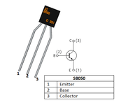
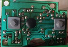


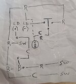
 Ok we made progress. The readings you gave for the transistor prove that it is a NPN and that it is ok. And we are sure about the base connection and just need to confirm the emitter and collector.