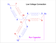
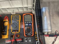
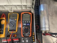
Cal Haines over on Practical Machinist was kind enough to draw up the various wire diagrams for connection the M/G motor to AC power.
Here is the standard 3 Phase High-Voltage wire Diagram

Here is the standard 3Phase Low Voltage diagram

Notice, the High Voltage Diagram have the motor's coils in SERIES with 4 coils between any of the Terminals. The Low Voltage diagram has them in PARALLEL .
Now looking at the Steelman connection diagram for converting the motor from 3Phase to single:

The T1 and T2 circuits are also in PARALLEL, however the T3 circuit is in SERIES. This is interesting. It brings up the question, can you use a start / run capacitor setup with the standard Low-Voltage connection to get a 2 Phase motor?
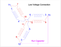
oth the Steelman and the Low-Voltage diagrams share the following jumpers
1~7
2~8
4~5
10~11
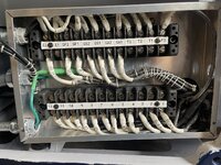
Noticing this, I then wired those jumpers and placed them behind the Generator wires as these connections will be used regardless, and they are all part of the original factory configuration.

I now have a good test bed to do some testing and see if it is possible to use the Low-voltage connection with a run capacitor to run on single phase, and see how it compares to the Steelman method of converting to single phase.
Testing any two coils in Series gives me 1.6Ω. This is good, as they all tested the same. This makes sense as testing each of the individual coils gave me readings between 0.8 and 0.9Ω so 0.8Ω plus 0.8Ω = 1.6Ω. Along those same lines, if we then wire two of the series of coils in parallel we would take the 1.6Ω divide it by 2 and we end back up with 0.8Ω same as what each individual coil tested at. The Electrical Theories that I "learned" back in the few EE classes I took in college are quite foggy, but this is at least making a bit of sense to me.
Ok, lets wire it up for the standard 3Phase Low Voltage connection and see what we get.

For this configuration we add the following jumpers
3~9
5~6
11~12
The motor is now in the 3 Phase low-voltage connection identical to the name plate.
Lets see what we get for the following connections
T1 ~ T2 = 0.9Ω
T1~T3 = 0.9Ω
T2~T3 = 0.9Ω
Ok this is what we would expect based upon the calculations above.
Now, lets remove the 3 sets of jumpers for the Low-Voltage connection and then wire it for the Steelman conversion:
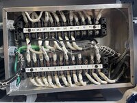
For this we add only two sets of jumpers
1~12
9~6
Now lets test our Terminal combinations again
T1 ~ T2 = 0.9Ω. Same as the standard low voltage connection above, since it is the same connections.
T1 ~ T3 = 1.6Ω Same as any two coils in series
T2 ~ T3 = 2.3Ω Interesting. Ok, looking back at when I tested the motor previously with the Steelman conversion, before the start cap blew, I was getting a voltage reading across T2 ~T3 of 400V. Interesting.. .thats high voltage territory. Humm.
Lets move the jumpers around and see what we get with the motor in the High-Voltage setting. In this setting, each combination of T1~T2, T1~T3 and T2~T3 is identical, in theory I can just test one of these and see what we get for resistance.

urns out it is 2.3Ω! That is exactly the same as I got with the T2~T3 connection in the Steelman configuration.
So this is making a bit more sense, as to why I got different voltages in my previous testing.
So in summary with the Steelman configuration
238.5V T1 ~ T2 = 0.9Ω. Same as the standard low voltage connection above, since it is the same connections.
296.8V T1 ~ T3 = 1.6Ω (two coils in series)
399.9V T2 ~ T3 = 2.3Ω
Since T2 ~T3 also has the start / run caps connected across them, I believe the higher voltages here make sense...(If I am thinking correctly, the capacitor is what provides the phase shift so the motor can start, and because of the phase shift, the meter is reading it as high voltage.
Next step is to add the start / run capacitor to the system and see where we are at. I really wish I had an oscilloscope for the next round of testing, just to better understand what exactly is going on.