To avoid these ads, REGISTER NOW!

Help with capacitor selection.

Grant Gunderson

Well-known member
Joined
May 17, 2013
Messages
2,330
Location
Bellingham, WA

Attachments

  • MG_Schematics.jpg
    MG_Schematics.jpg
    165.2 KB · Views: 26
Last edited:
To avoid these ads, REGISTER NOW!

RPH

Well-known member
Joined
Dec 17, 2006
Messages
4,190
Location
Michigan Thumb
First cap is start cap. Only used momentarily. Will blow with continuous use. Overheats.
Second cap appears functional. It’s used for power factor correction and filtering. That indicates continuous operation.
Third cap doesn’t really lists specifications. No data on it.
The 300 uf is notated as a start cap in drawing.
60 uf as run cap.
Higher voltage and extra micro farads will not hurt on most motor applications.
Less voltage blows up! With a bang.
 
OP
G

Grant Gunderson

Well-known member
Joined
May 17, 2013
Messages
2,330
Location
Bellingham, WA
First cap is start cap. Only used momentarily. Will blow with continuous use. Overheats.
Second cap appears functional. It’s used for power factor correction and filtering. That indicates continuous operation.
Third cap doesn’t really lists specifications. No data on it.
The 300 uf is notated as a start cap in drawing.
60 uf as run cap.
Higher voltage and extra micro farads will not hurt on most motor applications.
Less voltage blows up! With a bang.
Thanks! That second one might be the way to go, as I am guessing it will offer a little more "insurance"
And you mean blow up with a bang like this?
IMG_6153.jpeg
Either the Supco APR5 relay isn't dropping it out, or two many starts in a relative short time checking voltages / taking amp readings over heated it. I got 10 starts out of it before that happened.
Looks like you need a start capacitor. Bmi capacitors are good and that's what I use. 330v is a more common voltage rating and should work fine in your application.

You have to make sure that potential relay drops out since start capacitors cannot stay in the circuit for very long.

https://www.amazon.com/dp/B00TKQ46RS/?tag=atomicindus08-20
Thanks. I need to figure out a way to ideally best test the Supco Relay, and then set up a meter next time to see if the start cap is actually dropping out of circuit immediatley.
 

RPH

Well-known member
Joined
Dec 17, 2006
Messages
4,190
Location
Michigan Thumb
Like this,635D148B-A81C-4907-910D-DD286C048A63.jpeg
True story, I worked with a guy that was top notch electronic tech. Every now and then on board work he would insert a polarized electrolytic capacitors opposite polarity. You would here a 12 gage shell off, bunch of cussing. Come around the corner and it’s confetti and smoke everywhere.
Capacitors need to be respected. It might not kill you but the tingle from it might make you jump. The jump can kill you.
 
OP
G

Grant Gunderson

Well-known member
Joined
May 17, 2013
Messages
2,330
Location
Bellingham, WA
Capacitors need to be respected. It might not kill you but the tingle from it might make you jump. The jump can kill you.
I got a healthy respect for caps. Back in Highschool I worked at a audio / electronics shop and had quite the car stereo, that I had incorporate a couple of caps into to help out with the amp draw, I accidentally discharged one once, that scared the **** out of me!

Ok, time to do a post mortem and see if we can figure out WTF happened.

I removed the Capacitors and relays from the lathe, so they are out of the equation

First lets check the resistivity in the 3 sets of motor windings.
image.jpeg
T1 to T2 is 0.8Ω this is essentially across 4 of the windings.
T1 to #3 is 1.5Ω this is essentially across 2 of the windings
T2 to #3 is 2.2 Ω this is essentially across all the windings
image.jpeg
Here is the readings I got with my meter (red was while it was running before the cap failed. Blue was after the cap failed and with both the caps and the relay removed. The circles are where I took the readings with my clamp meter.

I dont think this is where the problem lies. If needed I can check each set of windings individually, or even break out my megger, but I'm feeling confident the motor is good.

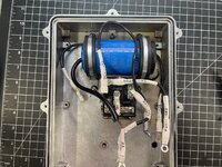
Ok, now lets look at what actually failed. I think the problem lies with one of these two components are a combination of.
image.jpeg

First lets look at the start cap. It blew the end right off of it. It appears to be made up of smaller caps. Lets have a look inside.
image.jpeg
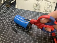
My Knipex electrician scissors made quick work of the plastic housing.

Thats a pretty sizable package for 4 small caps.
image.jpeg
Ok, what are the using for the caps in this?
image.jpeg
all 4 are 330uF 200WV caps.
image.jpeg
Ok, to me this looks like two sets of 330uF 200WV caps in series, then wired in parallel. Not sure how they are getting the 450V rating.
Can someone explain that to me, or verify my thinking that this should only have been rated at 200v? When I tested it prior to install with my fluke meter I got a reading of 308uF.

Ok, moving on to the Supco AR5 relay. Hey look, USA on the circuit board... you dont see that very often these days.
image.jpeg
The contacts feel stuck closed. With a bit of force from my finger I got them to open with a pop. Lets have a closer look at the contacts.
image.jpeg
That looks to me, like they did in fact weld themselves shut.

Ok, so what would cause the relay to weld its self shut? Too many amps? Too much voltage? Did I have the pickup voltage set too high on it?
The really was rated for 110 - 270 VAC, Single Phase 30 Amps

I am thinking a better quality cap is in order. Second, I need to see what the actual specs are for Supco Relay and varify with the meter what it is actually seeing. If anyone has any in site I all years as I am pushing my limited knowledge of this stuff.
 
Last edited:

Lightning rod

Well-known member
Joined
Dec 1, 2012
Messages
283
Location
Toronto , Ontario
The small caps are electrolytic type. (Negative terminal indicated)
The Working Volts (WV) on these is typically DC working volts.
Whats interesting that they rated 200 WV DC times two in series would normally
give 400 WV DC but they rated it as 450 WV AC .

Normally a DC rated cap can be run a little higher on AC but in this case these electrolytic
type don't like AC at all since they will see a polarity reversal every half cycle.

Interesting. I guess the caps can take short time , start AC voltages. ( I was taught ,no)

I would rather use a proper AC rated start cap (non-electrolytic)
 

RPH

Well-known member
Joined
Dec 17, 2006
Messages
4,190
Location
Michigan Thumb
Go up in ac voltage. That 399 volt line across the start cap is pushing the limit. Spikes are definitely possible. When the caps let loose the relay contacts become the arc point for discharge, a few joules went quickly!
 
OP
G

Grant Gunderson

Well-known member
Joined
May 17, 2013
Messages
2,330
Location
Bellingham, WA
Go up in ac voltage. That 399 volt line across the start cap is pushing the limit. Spikes are definitely possible. When the caps let loose the relay contacts become the arc point for discharge, a few joules went quickly!
The new one I ordered is rated at 430vac but it’s a continuous duty one not a start specific. What is the more common voltage sizes as I am having a hard time finding 300uf caps. Thanks
you could add a bleed resistor to help with the arcing.
That makes sense. How do I size the resistor for a 300uf cap?

Once the new parts arrive I think my plan is to test using two meters one to read the voltage across the coil section of the relay to verify it’s not receiving too much voltage. Second will be placed across cap to verify relay drops it out of circuit as motor comes to speed.

If I understand the theory correctly the start cap basically provides the 240v at 90 degrees to the 240v line voltage to get the motor moving thus it meters at 400+ bolts but thus should drop back to 240v line voltage once cap drops out of the circuit. Or at least that’s what I think is the intention with this circuit.
 
Last edited:

marinusdees

Well-known member
Joined
Oct 30, 2012
Messages
1,325
Location
Edgewood, Washington

rlitman

Well-known member
Joined
Oct 18, 2010
Messages
24,651
Location
Long Island
The new one I ordered is rated at 430vac but it’s a continuous duty one not a start specific. What is the more common voltage sizes as I am having a hard time finding 300uf caps. Thanks

That makes sense. How do I size the resistor for a 300uf cap?

Once the new parts arrive I think my plan is to test using two meters one to read the voltage across the coil section of the relay to verify it’s not receiving too much voltage. Second will be placed across cap to verify relay drops it out of circuit as motor comes to speed.

If I understand the theory correctly the start cap basically provides the 240v at 90 degrees to the 240v line voltage to get the motor moving thus it meters at 400+ bolts but thus should drop back to 240v line voltage once cap drops out of the circuit. Or at least that’s what I think is the intention with this circuit.
The hidden capacitors inside isn't a surprise. Typical metallized film capacitors (real AC "run" caps) pretty much top out at 250V. Anything higher than that uses series stacking to divide the voltage over the film down to manageable levels. Usually they pack one foil roll over another inside the same case. That start cap gets away with using FAR smaller DC electrolytic caps, only because it's not expected to see much run-time in service. They then had then in parallel to reach the value you needed.

300uF is pretty big in terms of an AC run capacitor. At work, I have some large banks made up from GE Genteq 000123L5 caps rated at 600V 40uF. But you'll quickly discover how much space something like this will take up.

Sizing a bleeder resistor is simple. You need a resistor that can handle enough watts to not burn itself up when connected to the line voltage. Higher resistances bleed more slowly, so they draw less watts, and less power draw directly equals less power dissipation.
 

American Locomotive

Well-known member
Joined
Jan 8, 2017
Messages
11,012
Location
Rhode Island
The small caps are electrolytic type. (Negative terminal indicated)
The Working Volts (WV) on these is typically DC working volts.
Whats interesting that they rated 200 WV DC times two in series would normally
give 400 WV DC but they rated it as 450 WV AC .

Normally a DC rated cap can be run a little higher on AC but in this case these electrolytic
type don't like AC at all since they will see a polarity reversal every half cycle.

Interesting. I guess the caps can take short time , start AC voltages. ( I was taught ,no)

I would rather use a proper AC rated start cap (non-electrolytic)
Almost all start-capacitors are electrolytic, even if "rated" for AC. Almost all start capacitors will grenade if left energized for too long.
 
OP
G

Grant Gunderson

Well-known member
Joined
May 17, 2013
Messages
2,330
Location
Bellingham, WA
The hidden capacitors inside isn't a surprise. Typical metallized film capacitors (real AC "run" caps) pretty much top out at 250V. Anything higher than that uses series stacking to divide the voltage over the film down to manageable levels. Usually they pack one foil roll over another inside the same case. That start cap gets away with using FAR smaller DC electrolytic caps, only because it's not expected to see much run-time in service. They then had then in parallel to reach the value you needed.
This makes a lot of since. That said I ordered a replacement continuous duty cap from Newark just in case the relay doesn’t drop it out soon enough.
300uF is pretty big in terms of an AC run capacitor. At work, I have some large banks made up from GE Genteq 000123L5 caps rated at 600V 40uF. But you'll quickly discover how much space something like this will take up.
The 309uF is the start cap here. The run cap is 60uF.

Sizing a bleeder resistor is simple. You need a resistor that can handle enough watts to not burn itself up when connected to the line voltage. Higher resistances bleed more slowly, so they draw less watts, and less power draw directly equals less power dissipation.
Thanks. I need to look into this more.
Almost all start-capacitors are electrolytic, even if "rated" for AC. Almost all start capacitors will grenade if left energized for too long.
Interesting. I’m thinking it was either too many starts too quickly or the relay didn’t drop out soon enough. Will retest with multiple meters to verify it’s dropping out and the coil voltage on the relay isn’t too high once the replacement parts arrive.
 

rlitman

Well-known member
Joined
Oct 18, 2010
Messages
24,651
Location
Long Island
...Thanks. I need to look into this more...
Think of it this way (as a hypothetical example to ponder, but not a great use case). A lightbulb makes a functional bleeder. Though in your case, you'd need two bulbs in series to handle 240V.

So, starting out with 10W (a number I just pulled out of the air), and 240V, you'd need a resistor that's at least 5760 ohms, since lower resistance ratings will burn up that 10W resistor. Looking on eBay, I see tons of 2W 15k ohm bleeder resistors. Those will burn up at 3.84W when fed 240V. But 56k ohm resistors will only use just over 1W at 240V, so if they're 2W rated, they'll be fine for you.
 
OP
G

Grant Gunderson

Well-known member
Joined
May 17, 2013
Messages
2,330
Location
Bellingham, WA
Think of it this way (as a hypothetical example to ponder, but not a great use case). A lightbulb makes a functional bleeder. Though in your case, you'd need two bulbs in series to handle 240V.

So, starting out with 10W (a number I just pulled out of the air), and 240V, you'd need a resistor that's at least 5760 ohms, since lower resistance ratings will burn up that 10W resistor. Looking on eBay, I see tons of 2W 15k ohm bleeder resistors. Those will burn up at 3.84W when fed 240V. But 56k ohm resistors will only use just over 1W at 240V, so if they're 2W rated, they'll be fine for you.
Thanks!
So these one should work?https://www.amazon.com/gp/product/B08MLDYGKT/?tag=atomicindus08-20
 
To avoid these ads, REGISTER NOW!

RPH

Well-known member
Joined
Dec 17, 2006
Messages
4,190
Location
Michigan Thumb
C50DD3B6-DC39-4766-8A17-BA98BCC7FA07.jpegThe only concern I have is the 400 v wild leg. Your meter is an rms measuring device. The peak voltage across the cap is much higher that the meter shows. 400*1.414 = 565 volt peak. Now peak to peak which is 1, 131 volts. Capacitors will take a beating but will destroy themselves with abuse.
I think you need higher voltage ratings on the capacitor according to your measurement.
Here are the water cooled units used on power circuits in my line of work.
 
OP
G

Grant Gunderson

Well-known member
Joined
May 17, 2013
Messages
2,330
Location
Bellingham, WA
Huh? Why are you doubling it? 565 IS the peak to peak voltage.
Also, AC caps are rated in RMS voltage, so they take this into account, so 400V = 400V.
I ordered This Cap, its rated for 440VAC-RMS

I thinking the coil voltage for the relay I used was too high, I also ordered a new relay with a 420V coil rating and a 212/232 pickup min/max, 121 drop max rating.

In case that pick up is too low, I will try this one.

For the bleed resistor they guy at the local VHF radio store gave me a couple of 56K resistors to use.
IMG_6210.jpeg
I will place it here:
MG_Schematics_readings.jpg
Is it advisable to add a bleed resistor to the run cap? It seems to me that the circuit would automatically bleed that one down with the motor? correct?
 

fitter30

Well-known member
Joined
Jun 23, 2019
Messages
2,992
Location
Peace Valley,mo
Never in 50 years of running hvac service work have I've ever seen or heard of someone trying to do what your doing. I'd just use a vfd single to three phase just have to double or little more the amp rating of vfd.
 

Max

ALLIANCE MEMBER
Joined
Jun 16, 2018
Messages
3,351
Location
Georgia
Just a couple of thoughts on the cap that blew up;

1. Assuming two equally rated caps for working voltage and capacitance: Caps in series double their working voltage and halve their capacitance. In parallel the working voltage is the same as on the cap, but the capacitance adds to twice as large.
2. For caps in series some people are concerned that if the caps are not closely enough matched then the overall applied voltage is not split equally and one cap will be over stressed and fail. There is a good case to be made both ways, but in practice some manufacturers use this approach to make larger values. I haven’t done experiments myself or seen a good paper with test data so YMMV.
3. A cheap (the marketing folks would say “value priced”) way to make a non polarized cap out of electrolytic caps is to put two of them in series “back to back”, ie either plus to plus or minus to minus where they join. Each cap protects the other from being reverse biased by AC, and you still get 2x the working voltage and half the capacitance per pair.
4. Put two polarized 330 mF 200V caps in series the right way and you get 165 mF, 400V non polarized. Put another pair of caps similarly hooked up in parallel and you get 330 mF 400V. It looks the overall cap is only rated 300 mF, but that rating is probably +50/-20% so no foul.
5. The caps are rated for 85 deg C, so not quite the cheapest out there, but for a motor 105C would be a lot better. Overall it’s a cost effective solution but far from the most robust.
 
OP
G

Grant Gunderson

Well-known member
Joined
May 17, 2013
Messages
2,330
Location
Bellingham, WA
I ordered a new Run capacitor from Newark as they are the only one that had one with the exact specs I was looking for in a continuous duty. Its 300uF and 440V. Only issue is that Newark's shipping division is completely incompetent and they shipped it in just a padded envelope instead of boxing it.
image.jpeg
Notice the terminals are bent! After dealing with their horrible customer service for over a week, they finally agreed to refund my card and I ordered a replacement. That one showed up a week latter, with the same packaging issues and the same bent terminals. I contacted them again, and still waiting on a response another week latter... I wont be doing business with them. They could at least use customer service reps based on this continent.

I'm hoping they will send a replacement in a box, third time is the charm, but we will see. I did test the last one after I bent the terminals back and it does test good.
image.jpeg
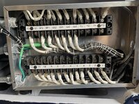
I then redid the terminal box on the M/G unit to make it cleaner and so that each motor lead had its own terminal.
image.jpeg
Thats way cleaner and more organized than my previous attempt. I'm glad I re-did it!
Next I tested each pair of windings with my Fluke meter
image.jpeg
I got the following results for each pair of motor windings:
1~4 = 0.9Ω
2~5 = 0.8Ω
3~6 = 0.9Ω
7~10 = 0.8Ω
8~11 = 0.9Ω
9~12 = 0.8Ω
Ok, resistance across each individual coil looks great!

Next, I tested motors insulation by testing each lead to ground with my Klein Megger
image.jpeg
I started off testing at 250V and got >4000MΩ for each lead to ground, I then redid the test at both 500V and again at 1KV and got the same >4000MΩ reading for each. Finally I tested between each motor Terminal and still got >4000MΩ with the exception of the coil pairs. So the motor is sound electrically. Not bad for a garage motor rebuild.
 
OP
G

Grant Gunderson

Well-known member
Joined
May 17, 2013
Messages
2,330
Location
Bellingham, WA
Cal Haines over on Practical Machinist was kind enough to draw up the various wire diagrams for connection the M/G motor to AC power.
Here is the standard 3 Phase High-Voltage wire Diagram
image.png
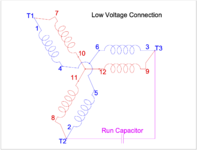
Here is the standard 3Phase Low Voltage diagram
image.png
Notice, the High Voltage Diagram have the motor's coils in SERIES with 4 coils between any of the Terminals. The Low Voltage diagram has them in PARALLEL .

Now looking at the Steelman connection diagram for converting the motor from 3Phase to single:
image.png

The T1 and T2 circuits are also in PARALLEL, however the T3 circuit is in SERIES. This is interesting. It brings up the question, can you use a start / run capacitor setup with the standard Low-Voltage connection to get a 2 Phase motor?
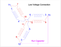
image.png
oth the Steelman and the Low-Voltage diagrams share the following jumpers
1~7
2~8
4~5
10~11

Noticing this, I then wired those jumpers and placed them behind the Generator wires as these connections will be used regardless, and they are all part of the original factory configuration.
image.jpeg
I now have a good test bed to do some testing and see if it is possible to use the Low-voltage connection with a run capacitor to run on single phase, and see how it compares to the Steelman method of converting to single phase.

Testing any two coils in Series gives me 1.6Ω. This is good, as they all tested the same. This makes sense as testing each of the individual coils gave me readings between 0.8 and 0.9Ω so 0.8Ω plus 0.8Ω = 1.6Ω. Along those same lines, if we then wire two of the series of coils in parallel we would take the 1.6Ω divide it by 2 and we end back up with 0.8Ω same as what each individual coil tested at. The Electrical Theories that I "learned" back in the few EE classes I took in college are quite foggy, but this is at least making a bit of sense to me.

Ok, lets wire it up for the standard 3Phase Low Voltage connection and see what we get.
image.jpeg
For this configuration we add the following jumpers
3~9
5~6
11~12
The motor is now in the 3 Phase low-voltage connection identical to the name plate.
Lets see what we get for the following connections
T1 ~ T2 = 0.9Ω
T1~T3 = 0.9Ω
T2~T3 = 0.9Ω
Ok this is what we would expect based upon the calculations above.

Now, lets remove the 3 sets of jumpers for the Low-Voltage connection and then wire it for the Steelman conversion:
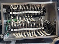
image.jpeg

For this we add only two sets of jumpers
1~12
9~6

Now lets test our Terminal combinations again
T1 ~ T2 = 0.9Ω. Same as the standard low voltage connection above, since it is the same connections.
T1 ~ T3 = 1.6Ω Same as any two coils in series
T2 ~ T3 = 2.3Ω Interesting. Ok, looking back at when I tested the motor previously with the Steelman conversion, before the start cap blew, I was getting a voltage reading across T2 ~T3 of 400V. Interesting.. .thats high voltage territory. Humm.

Lets move the jumpers around and see what we get with the motor in the High-Voltage setting. In this setting, each combination of T1~T2, T1~T3 and T2~T3 is identical, in theory I can just test one of these and see what we get for resistance.
image.jpeg
urns out it is 2.3Ω! That is exactly the same as I got with the T2~T3 connection in the Steelman configuration.

So this is making a bit more sense, as to why I got different voltages in my previous testing.

So in summary with the Steelman configuration

238.5V T1 ~ T2 = 0.9Ω. Same as the standard low voltage connection above, since it is the same connections.
296.8V T1 ~ T3 = 1.6Ω (two coils in series)
399.9V T2 ~ T3 = 2.3Ω

Since T2 ~T3 also has the start / run caps connected across them, I believe the higher voltages here make sense...(If I am thinking correctly, the capacitor is what provides the phase shift so the motor can start, and because of the phase shift, the meter is reading it as high voltage.

Next step is to add the start / run capacitor to the system and see where we are at. I really wish I had an oscilloscope for the next round of testing, just to better understand what exactly is going on.
 
OP
G

Grant Gunderson

Well-known member
Joined
May 17, 2013
Messages
2,330
Location
Bellingham, WA
Ok, thinking about this some more,

After measuring resistance in each configuration, I dont think the Low-voltage with the caps across T2T3 is going to work.
image.png
In the standard, Low-Voltage configuration we get:
The motor is now in the 3 Phase low-voltage connection identical to the name plate.
Lets see what we get for the following connections
T1 ~ T2 = 0.9Ω
T1~T3 = 0.9Ω
T2~T3 = 0.9Ω
Thats with each terminal set seeing 220/240V across it.

With the Steelman configuration
image.png
T1 ~ T2 = 0.9Ω. Same as the standard low voltage connection above, since it is the same connections.
T1 ~ T3 = 1.6Ω Same as any two coils in series
T2 ~ T3 = 2.3Ω Interesting. Ok, looking back at when I tested the motor previously with the Steelman conversion, before the start cap blew, I was getting a voltage reading across T2 ~T3 of 400V. Interesting.. .thats high voltage territory. Humm.

in the High-Voltage setting it is 2.3Ω between any two combinations of T1,2,3

So based upon the voltages I got from my attempt prior to the start cap blowing in my previous tests, I got
So in summary with the Steelman configuration it is wired to handle the high voltage across T2~T3

238.5V T1 ~ T2 = 0.9Ω. Same as the standard low voltage connection above, since it is the same connections.
296.8V T1 ~ T3 = 1.6Ω (two coils in series)
399.9V T2 ~ T3 = 2.3Ω Same as the standard 3 Phase HV connection.

The low-Voltage option with the run capacitor would not be, if I’m not mistaken.

Going back to the first thing in the Steelman manual: "it is important to remember that T1 and T2 two lines will be carrying more amperage than the nameplate of a three phase motor will indicate. This is true because it will be carrying the same total power on two lines that it would be carrying on three lines when operating on three phase. The current required from single phase lines times 1.73 delivers the same power as three phase provided that the system efficiency and power factors are the same.”

Thoughts?
 

Flail

Well-known member
Joined
Aug 5, 2016
Messages
412
Location
Kin folk said, “Californias the place you wanna be
Wow. I haven’t thought about this project in years as life has got in the way: https://www.practicalmachinist.com/...to-single-phase-steelman-method.274956/page-3

When I started this project in 2013 I realized a vfd was a no go as it would take a oversized vfd to power the three phase motor that runs the generator that powers the dc motor. A vfd would have to run at 60hz and would provide no speed control of this complicated system the Monarch employs. The dc speed control is so smooth compared to the notchiness at slow speed of a vfd I have on another lathe.

So you must have opened up the three phase motor and rewired it as per my original article? After reading this I went out to the shop and plugged my monarch in to 220 v single phase and it fired right up and ran fine after sitting dormant for 5 years. So cool to see someone carrying on with this. Hopefully in about a 1/2 year when my life settles down I can get back to this project as well as several others.
 
OP
G

Grant Gunderson

Well-known member
Joined
May 17, 2013
Messages
2,330
Location
Bellingham, WA
Wow. I haven’t thought about this project in years as life has got in the way: https://www.practicalmachinist.com/...to-single-phase-steelman-method.274956/page-3

When I started this project in 2013 I realized a vfd was a no go as it would take a oversized vfd to power the three phase motor that runs the generator that powers the dc motor. A vfd would have to run at 60hz and would provide no speed control of this complicated system the Monarch employs. The dc speed control is so smooth compared to the notchiness at slow speed of a vfd I have on another lathe.

So you must have opened up the three phase motor and rewired it as per my original article? After reading this I went out to the shop and plugged my monarch in to 220 v single phase and it fired right up and ran fine after sitting dormant for 5 years. So cool to see someone carrying on with this. Hopefully in about a 1/2 year when my life settles down I can get back to this project as well as several others.
I did open up the motor, and rewired it per your original article, along with some help form the other thread on PM as well a the Steelman website. I actually went through the entire electrical system of the lathe, including the DC motor and the Exciter. Here is the full thread on the rebuild.

I am getting pretty close to having it all sorted. On first attempt it powered right up quite few times until the sketchy Chinese start cap blew. So I have proof of concept. I have replaced that with a legitimate cap thats rates for continuous duty to prevent that.

I am curious as to what relay did you use for your conversion was it the Supco APR5? Or something else. In my testing, it seems that the voltage across the coil was too high for the APR5, so I am going to do the next testing with a Supco relay rated for 430V across the coil.

Thanks.
 

nadogail

Well-known member
Joined
Jan 23, 2009
Messages
32,040
Location
Coronado, CA
About 25 years ago, I was exploring the possibility of making a single to three phase rotary converter from a three phase motor.

I recall that the material I found recommended 25 MFD per Horse Power. I never built the rotary converter, my ideas were bigger than my resources.
 

rlitman

Well-known member
Joined
Oct 18, 2010
Messages
24,651
Location
Long Island
I ordered a new Run capacitor from Newark as they are the only one that had one with the exact specs I was looking for in a continuous duty. Its 300uF and 440V. Only issue is that Newark's shipping division is completely incompetent and they shipped it in just a padded envelope instead of boxing it.
image.jpeg
Notice the terminals are bent! After dealing with their horrible customer service for over a week, they finally agreed to refund my card and I ordered a replacement. That one showed up a week latter, with the same packaging issues and the same bent terminals. I contacted them again, and still waiting on a response another week latter... I wont be doing business with them. They could at least use customer service reps based on this continent.

I'm hoping they will send a replacement in a box, third time is the charm, but we will see. I did test the last one after I bent the terminals back and it does test good...

Interesting. My understanding is that the way the terminal bulkhead ends on run caps work, they make a pressure contact with the foil packs inside. Should there be arcing inside that builds up gas, the flat end will dome out, breaking that contact by forcing the terminals away from the foil. If this is build that way, you'd have likely measured an open circuit while the terminals were bent. Or if bent the other way, the foil could have even been damaged, altering the value.
 

American Locomotive

Well-known member
Joined
Jan 8, 2017
Messages
11,012
Location
Rhode Island
Your idea to put a run cap across T2>T3 with the motor configured in its "normal" low voltage wiring, is the exact same thing that a static phase converter does. It gives just enough phase shift to the 3rd winding to get it going, and that's about it. You get 2/3rds the rated power.

I'm not enough of an EE to understand exactly what the "steelman method" is doing. But just looking at the schematic, it's seems to be putting the "T3" coils in series, and then putting them across the line with a capacitor. You can honestly almost think of it as a completely independent winding from the rest of the motor at that point. I think from a physics point of view, that's basically what it's doing. Its essentially two separate motors working on the same rotor, with the second motor being phase-shifted with a capacitor compared to the first.
 
OP
G

Grant Gunderson

Well-known member
Joined
May 17, 2013
Messages
2,330
Location
Bellingham, WA
Interesting. My understanding is that the way the terminal bulkhead ends on run caps work, they make a pressure contact with the foil packs inside. Should there be arcing inside that builds up gas, the flat end will dome out, breaking that contact by forcing the terminals away from the foil. If this is build that way, you'd have likely measured an open circuit while the terminals were bent. Or if bent the other way, the foil could have even been damaged, altering the value.
Thanks for the info. After another weeks worth of emails to Newarks customer service, they finally responded today saying they are refunding my CC and are unable to issue me a RA number for an exchange. I'm a firm believer that any company that outsources its customer service to a foreign land isn't long for this world, and I sure has hell wont be placing another order with Newark ever again. Especially when Digi-Key is so much easier to deal with. I now own two caps that cost me nothing other than a headache.

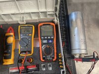
Testing the caps after I bent the pins back straight, the first one reads 296uF
IMG_6517.jpeg
and 0.946MΩ
IMG_6521.jpeg
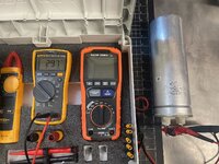
The second cap reads 297uF
IMG_6518.jpeg
But it reads 14.51MΩ
IMG_6520.jpeg
So I am thinking one of these is bad. Am I correct in my thinking that the bad one is the 0.946MΩ one?
Your idea to put a run cap across T2>T3 with the motor configured in its "normal" low voltage wiring, is the exact same thing that a static phase converter does. It gives just enough phase shift to the 3rd winding to get it going, and that's about it. You get 2/3rds the rated power.

I'm not enough of an EE to understand exactly what the "steelman method" is doing. But just looking at the schematic, it's seems to be putting the "T3" coils in series, and then putting them across the line with a capacitor. You can honestly almost think of it as a completely independent winding from the rest of the motor at that point. I think from a physics point of view, that's basically what it's doing. Its essentially two separate motors working on the same rotor, with the second motor being phase-shifted with a capacitor compared to the first.
Thanks I had another guy also point out that circuit is the same as a standard circuit as a static phase converter. From the research that I have done the Steelman method, allows for full name plate rating power of the motor. However at the cost of efficiency. Wanting to better understand it, I ordered an Oscilloscope, so once that arrives I will proceed to test both configs. I haven't used a scope since college, so its going to be a bit of a learning curve. I ended up buying a Pico 2204A and Hantek Current Clamp in addition to two high voltage 1:100 probes. Hopefully thats the correct combination needed to test.
 

rlitman

Well-known member
Joined
Oct 18, 2010
Messages
24,651
Location
Long Island
...So I am thinking one of these is bad. Am I correct in my thinking that the bad one is the 0.946MΩ one?...
A capacitor should eventually read as an open circuit with an ohmmeter like that, because capacitors do not pass DC. However, ohm meters inject a voltage and read the current to infer resistance. That voltage will slowly charge the cap, giving an early false reading of low resistance that rises as the current falls off, so the measurement you're showing is just a measure of time, and not the cap itself. I have an ESR meter for testing caps at work, but that's WAY overkill for you (and not really necessary when you own a scope; I got mine because I needed to test hundreds at a time).

I'd say that they seem fine and you got lucky, but they're certainly not built to take that sort of abuse, because the bulkhead end is designed specifically to break free of the foil pack as a fail safe.

I would also suggest using a clamp meter to watch the current flow into your capacitor banks under load. If they're out of balance, that's a potential sign of trouble.
 
OP
G

Grant Gunderson

Well-known member
Joined
May 17, 2013
Messages
2,330
Location
Bellingham, WA
A capacitor should eventually read as an open circuit with an ohmmeter like that, because capacitors do not pass DC. However, ohm meters inject a voltage and read the current to infer resistance. That voltage will slowly charge the cap, giving an early false reading of low resistance that rises as the current falls off, so the measurement you're showing is just a measure of time, and not the cap itself. I have an ESR meter for testing caps at work, but that's WAY overkill for you (and not really necessary when you own a scope; I got mine because I needed to test hundreds at a time).

I'd say that they seem fine and you got lucky, but they're certainly not built to take that sort of abuse, because the bulkhead end is designed specifically to break free of the foil pack as a fail safe.

I would also suggest using a clamp meter to watch the current flow into your capacitor banks under load. If they're out of balance, that's a potential sign of trouble.
Thanks!
 
To avoid these ads, REGISTER NOW!
Top Bottom