
You are using an out of date browser. It may not display this or other websites correctly.
You should upgrade or use an alternative browser.
You should upgrade or use an alternative browser.
110 Outlets not working
- Thread starter DocPhilMD
- Start date
Dustball
Well-known member
I told him to unhook them from the load side of the gfi while doing it to make sure its isolated from rest of the circuit.")
I thought we were focusing on the wiring between the GFCI outlet and the panel since we've confirmed the GFCI will not reset on it's own with the load wires disconnected.
zmaxmotorsports
Well-known member
No I was trying to eliminate a fault on the load side as being the cause of the gfis going south on him,something has got to be killing the gfci's.
zmaxmotorsports
Well-known member
Well I guess we are back to replacing the gfi again.This time hook up the line side and check for power on the load side screws before hooking the garage outlets to the gfi.
If everything is good that way kill the power and hook up the load side before turning power back on and see what you get.
When you take the gfi back just tell them it didnt work and you want to swap it,dont mention the other issues .
If everything is good that way kill the power and hook up the load side before turning power back on and see what you get.
When you take the gfi back just tell them it didnt work and you want to swap it,dont mention the other issues .
Zeke
Well-known member
This is still going? 
Okay. I will get a new GFCI and do that.
By the way, I ohmed the line side just for fun and it did make a sound.
Perhaps this indicates a problem upstream?
Interestingly, when the GFCI is flipped and connected, there are 3 other light switches and an outlet that work. But, when I flip the breaker, they don't work.
So there must be some kind of accessory circuit that branches off and supplies power to these 4 things before it hooks up with the GFCI. Just thought that was interesting.
Could it still be upstream from the GFCI if I am getting 120V on the line side and all of those other things work?
zmaxmotorsports
Well-known member
Okay. I will get a new GFCI and do that.
By the way, I ohmed the line side just for fun and it did make a sound.
Perhaps this indicates a problem upstream?
Interestingly, when the GFCI is flipped and connected, there are 3 other light switches and an outlet that work. But, when I flip the breaker, they don't work.
So there must be some kind of accessory circuit that branches off and supplies power to these 4 things before it hooks up with the GFCI. Just thought that was interesting.
Could it still be upstream from the GFCI if I am getting 120V on the line side and all of those other things work?
What 2 wires was it between when it buzzed?
zmaxmotorsports
Well-known member
Sounds like an issue downstream/load side of gfi.Okay. I will get a new GFCI and do that.
By the way, I ohmed the line side just for fun and it did make a sound.
Perhaps this indicates a problem upstream?
Interestingly, when the GFCI is flipped and connected, there are 3 other light switches and an outlet that work. But, when I flip the breaker, they don't work.
So there must be some kind of accessory circuit that branches off and supplies power to these 4 things before it hooks up with the GFCI. Just thought that was interesting.
Could it still be upstream from the GFCI if I am getting 120V on the line side and all of those other things work?
zmaxmotorsports
Well-known member
It was the hot and neutral from the line side
Thats your fault in the circuit weve been looking for,can you unhook the wires in each box to isolate which part of the circuit has the short?
Thats your fault in the circuit weve been looking for,can you unhook the wires in each box to isolate which part of the circuit has the short?
Did you see my next post? There is a buzz between hot and neutral, neutral and ground and hot and ground.
This isn't normal?
zmaxmotorsports
Well-known member
Did you see my next post? There is a buzz between hot and neutral, neutral and ground and hot and ground.
This isn't normal?
As long as nothing is plugged in you should have nothing showing between them.
If you had something plugged in the worst case scenario should be continuity between the black and white because a circuit is being completed.
Having continuity between the black and ground is a dead short.
Has anything been mounted/screwed or nailed on a wall recently in that area?
Always start with the simple stuff.
So I would be looking for a problem in the wire between the GFCI and the breaker correct?
zmaxmotorsports
Well-known member
So I would be looking for a problem in the wire between the GFCI and the breaker correct?
Did it buzz between the panel and gfi or between the gfi and garage outlets?
Opps just reread your post,pay no attention to the line side of the circuit.
We're trying to eliminate the load side past the gfi as the problem.
The line side can be reading through other devices on the circuit,the ground and neutral are connected on the buss in your main panel.
Thats why its buzzing.
Last edited:
JimRB
Well-known member
These two videos explain house wiring 101 and GFCI in short order.
JimRB
Well-known member
An ohm meter or continuity tester (not necessarily the same thing) work when you unscrew all the light bulbs upstream and unplug all appliances and lights upstream, and you turn off the breaker that protects that wiring. That is if you are looking for shorted wires. Any device that makes a connection between black and white wires (like a light bulb or a tv set or radio) are going to mess up continuity and ohm readings. An ohm meter or continuity tester is not necessarily going to show you loose connections that can read continuity but may not flow a decent quantity of amps.
checkthisout
Well-known member
- Joined
- Sep 5, 2008
- Messages
- 5,232
Ok so the load side didn't buzz.
So we're back to the GFCI correct?
Questions:
1)Does your new GFCI reset and work with just the power wires (line in) hooked to it?
Yes or no?
This thread is long and confusing but if you read my posts closely I have been very methodical and followed all advice given here.
So far I know
1)the new GFCI doesn't work with or without load connected
2)I'm getting 120 volts from the line from the breaker
3)if I bypass the GFCI all 3 plugs downstream work
4)GFCI will not reset with or without load attached
5)no current when I ohmed the load wires.
So what now? Get another GFCI?
checkthisout
Well-known member
- Joined
- Sep 5, 2008
- Messages
- 5,232
Nope
Ok, so please confirm:
With the just the line side (incoming power) of the GFCI hooked up, you turn the power on at the breaker and then go to reset the GFCI and it won't reset, correct? GFCI's cannot be reset without the incoming power being turned on first.
If that's the case, go to a known good outlet in the house, remove the outlet and install that GFCI and see if it will reset.
Ok, so please confirm:
With the just the line of the GFCI hooked up, you turn the power on at the breaker and the GFCI won't reset, correct? GFCI's cannot be reset without incoming power.
If that's the case, go to a known good outlet in the house, remove the outlet and install that GFCI and see if it will reset.
Yes that is correct. I will pick up a new GFCI tomorrow and if it doesn't work I will do this
checkthisout
Well-known member
- Joined
- Sep 5, 2008
- Messages
- 5,232
Yes that is correct. I will pick up a new GFCI tomorrow and if it doesn't work I will do this
And also note that it takes a substantial push to get it to reset.

sammer
Active member
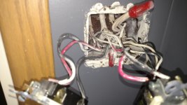
I'm really confused by the pic of the wires and pigtails coming out of the wall.
Why are there 2 hot and 2 neutrals in all the pigtails.
This makes me think this is in the middle of a circuit.
I would think that there should only be a single hot and neutral to the line side of the gfci.
Where are the other line wires going?
And ya that panel is a mess!
sam
Why are there 2 hot and 2 neutrals in all the pigtails.
This makes me think this is in the middle of a circuit.
I would think that there should only be a single hot and neutral to the line side of the gfci.
Where are the other line wires going?
And ya that panel is a mess!
sam
Sam, I think there is a circuit that branches off before the GFCI then comes back in.
I know this because there are 3 light switches and a plug on the same breaker that work when the GFCI is flipped. So they must be getting power before the GFCI.
In my original sketch I wasn't aware of this outlet. I just found it today. And another light switch.
As for two loads it is because there are 2 circuits coming out of the GFCI. One terminates in the outside outlet and one in the garage by way of the other bathroom.
So it is kind of in the middle of a circuit I believe. But it is still getting good power to it
checkthisout
Well-known member
- Joined
- Sep 5, 2008
- Messages
- 5,232
Okay. I have some updates and pics. I checked all the outlets. A couple were cracked and the ground on the garage outlet look fried. I replaced two overall. The GFCI still wouldn't work
So then I bypassed the GFCI and ALL the outlets worked fine!
So, I am stuck now. I attached some pics of the box and lines coming out and how I wired up the GFCI
In the pic of the box, the wires that comes out of the bottom are 120V between them. So I hooked these to "line". The top two were hooked to load. I checked all connections, wire nuts, etc and everything was fine. One thing I noted was that when my nephew flipped on the GFCI, the LED flashed RED for a sec then went off. The other GFCI didn't do this (the original one).
So what now?
Sorry, I didn't see this post. Don't know how I missed it.
The wiring in the place is a mess. That box is overfilled by quite a bit especially since you have to stuff a GFCI in there too.
checkthisout
Well-known member
- Joined
- Sep 5, 2008
- Messages
- 5,232
Did you confirm that the hot and neutral you hooked up to the outlet came from the same piece of Romex?
I.E. were they both in the same jacket?
That's why I want you to try the outlet on another known good circuit first.
I.E. were they both in the same jacket?
That's why I want you to try the outlet on another known good circuit first.
Last edited:
wyliesdiesels
Well-known member
Did you confirm that the hot and neutral you hooked up to the outlet came from the same piece of Romex?
I.E. were they both in the same jacket?
That's why I want you to try the outlet on another known good circuit first.
Why would that matter?
The GFCI doesnt give a hoot about whats going on on the line side...
The OP confirmed the feed to the GFCI is fine....
wyliesdiesels
Well-known member
So Wylie what is your recommendation as the next step? New GFCI?
Well I have seen bad GFCIs out of the box.
But just to save u a trip to the store, can u try the GFCI at a known good outlet location? Only connect the supply/line side to the GFCI and see if u can reset it. If not, then exchange it for another one.
What brand of GFCI is it?
Ok. I'm pretty much ready to give up on this. I got a new GFCI and it still won't work.
I mentioned that accessory circuit before that still works when the GFCI is off but doesn't work when the breaker is off. It contains the light switch in the bathroom, the dual light switch in the hallway and the single light switch near the kitchen. The switch on the right and the switch near the kitchen control the same light. Plus the outlet near the kitchen light switch is in the circui.
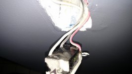
I pulled those switches apart too and the dual one near the front door is a hot mess. Nothing is burnt is fried, but T=this one confused the **** out of me so I basically didn't even both to study it. The other two looked ok but the one thing I did notice was that none of the light switches had the ground attached to the switch. They were just wired together. Here's some pics.
Unless anyone has some magical ideas I'm about ready to jump the GFCI so the other outlets work. Can I do this?
I mentioned that accessory circuit before that still works when the GFCI is off but doesn't work when the breaker is off. It contains the light switch in the bathroom, the dual light switch in the hallway and the single light switch near the kitchen. The switch on the right and the switch near the kitchen control the same light. Plus the outlet near the kitchen light switch is in the circui.
I pulled those switches apart too and the dual one near the front door is a hot mess. Nothing is burnt is fried, but T=this one confused the **** out of me so I basically didn't even both to study it. The other two looked ok but the one thing I did notice was that none of the light switches had the ground attached to the switch. They were just wired together. Here's some pics.
Unless anyone has some magical ideas I'm about ready to jump the GFCI so the other outlets work. Can I do this?
Attachments

Dick in Wisconsin
Well-known member
Ok. I'm pretty much ready to give up on this. I got a new GFCI and it still won't work.
I mentioned that accessory circuit before that still works when the GFCI is off but doesn't work when the breaker is off.
I don't blame you!
"when the GFCI is off" ... "doesn't work when the breaker is off".
I understand a circuit not working when the breaker is off. But I don't understand what you mean by "when the GFCI is off". Do you mean when you've unhooked the GFCI and taken it out of the circuit?
Let me recap what I understand ...
1. Remove the GFCI from the circuit, wire the line hot & neutral to the load hot & neutral wires, respectively, (effectively "jumping" the GFCI) the downstream outlets work. Correct?
2. Put the GFCI back into the circuit with the line hot & neutral wires hooked to the line lugs and the load hot & neutral wires hooked to the load lugs and ... (a) you can't reset the GFCI to get the little green light to come on and (b) the downstream outlets obviously don't work.
When you're in situation #2 above, have you tried the GFCI outlet tester? Does anything light up? I presume that nothing would light up. Let us know what happens.
I wonder if the line and load wires have been transposed; i.e. you're hooking the incoming line wires (that are hot from the breaker) to the line side. When you're in stuation #2 above, what happens when you use the DMM to check the voltage? Check the voltage both on the line lugs and the load lugs. If you get 120 volts on the load lugs, the GFCI is wired backwards.
Being a regular guy and not an electrician, I don't know what impact having the line and load hots hooked up right on the GFCI and the neutrals transposed.
With the GFCI out of the circuit and bare wires hanging there, you can put the breaker on confirm which hot is the line (using either a test light or the DMM).
I pulled those switches apart too and the dual one near the front door is a hot mess. Nothing is burnt is fried, but T=this one confused the **** out of me so I basically didn't even both to study it. The other two looked ok but the one thing I did notice was that none of the light switches had the ground attached to the switch. They were just wired together.
Please expound on "nothing is burnt is fried, but T=this one confused the **** out of me ... ". I'm having trouble visualizing what you were presented with when you pulled the things apart.
Unless anyone has some magical ideas I'm about ready to jump the GFCI so the other outlets work. Can I do this?
Doing that obviously would NOT be code. One option you have to replace all the outlets with GFCI outlets. Hook both the line and load wires to the line lugs only, disregard the load lugs. Each outlet then is responsible for protecting itself independent of the other outlets. This way you can have one outlet trip its GFCI, and it won't kill anything other outlet on the same circuit. I hope this is code and correct, I've done it in my house (two bathrooms and the garage on the same GFCI, now three GFCI's independent of each other). If this is wrong, I'm sure the properly trained electricians will gently let know how wrong I am.
Keep plugging away.
wyliesdiesels
Well-known member
Ok. I'm pretty much ready to give up on this. I got a new GFCI and it still won't work.
I mentioned that accessory circuit before that still works when the GFCI is off but doesn't work when the breaker is off. It contains the light switch in the bathroom, the dual light switch in the hallway and the single light switch near the kitchen. The switch on the right and the switch near the kitchen control the same light. Plus the outlet near the kitchen light switch is in the circui.
I pulled those switches apart too and the dual one near the front door is a hot mess. Nothing is burnt is fried, but T=this one confused the **** out of me so I basically didn't even both to study it. The other two looked ok but the one thing I did notice was that none of the light switches had the ground attached to the switch. They were just wired together. Here's some pics.
Unless anyone has some magical ideas I'm about ready to jump the GFCI so the other outlets work. Can I do this?
Those are 3-way switches. Nothing out of the ordinary.
Back to the GFCI. Forgive if i missed it but have u tried the GFCI by itself with nothing hooked up to the load side?
What about trying it in another location?
As far as this other stuff on the same circuit that u keep mentioning. If its before/upstream of the GFCI, ie in between the panel and GFCI, then it would work with the GFCI tripped/off. Thats because the GFCI only cares about whats happening on the load side of the GFCI.
checkthisout
Well-known member
- Joined
- Sep 5, 2008
- Messages
- 5,232
OP, forget what I said earlier. I looked at the photo of the outlet and realize you're hooking the GFCI to the pigtails that are wirenutted onto the other two wires.
Remove the wirenuts on the pigtails on which you are detecting voltage and isolate it down to the wires coming out of 1 piece of romex. Then, hook your GFCI outlet to that and attempt to reset. If no reset, install a regular outlet and test it with an actual load.
Remove the wirenuts on the pigtails on which you are detecting voltage and isolate it down to the wires coming out of 1 piece of romex. Then, hook your GFCI outlet to that and attempt to reset. If no reset, install a regular outlet and test it with an actual load.
Last edited:
checkthisout
Well-known member
- Joined
- Sep 5, 2008
- Messages
- 5,232
Why would that matter?
The GFCI doesnt give a hoot about whats going on on the line side...
The OP confirmed the feed to the GFCI is fine....
No, he didn't test it under an actual load. He only tested it with a DVOM.
Now I get to teach you something for once!
I have a hunch the hot or neutral is in series with another load. This won't show up with a DVOM unless the voltage Is checked with a load attached.
happy2rv
Well-known member
I suspect you either have a neutral shorted to ground somewhere or neutrals from two circuits tied together somewhere. Probably the latter.
I always thought that GFCI only sensed the load side, but I've read several sources that indicate a upstream combination of neutrals from multiple circuits can be a problem. It should be easy enough to verify if this is the problem. Fixing it if it is the problem might not be quite as easy. It may be hard to track down where the neutrals are combined if you can't readily identify the endpoints of all wires involved at every electrical box involved.
I believe that I would try to identify which wire coming into the first outlet is direct from the breaker panel (assuming it's coming directly to that box and not being fed from one of the other boxes). Then I would temporarily disconnect all of the other circuits and attach just the wire directly from the breaker panel to the line lugs on the GFCI. Cap everything else off, turn the breaker on, and see if the GFCI will reset. If it does, then flip the break back off, leave the switches and other non GFCI upstream circuits disconnected, hook the downstream outlets to the load lugs of the GFCI, and turn the breaker back on. If it still works, you know you've got something with the switches and can start really investigating that path. With the 3 way switches, I would be willing to bet that somewhere you've got the neutral lines of 2 circuits tied together somewhere.
I suspect you either have a neutral shorted to ground somewhere or neutrals from two circuits tied together somewhere. Probably the latter.
I always thought that GFCI only sensed the load side, but I've read several sources that indicate a upstream combination of neutrals from multiple circuits can be a problem. It should be easy enough to verify if this is the problem. Fixing it if it is the problem might not be quite as easy. It may be hard to track down where the neutrals are combined if you can't readily identify the endpoints of all wires involved at every electrical box involved.
I believe that I would try to identify which wire coming into the first outlet is direct from the breaker panel (assuming it's coming directly to that box and not being fed from one of the other boxes). Then I would temporarily disconnect all of the other circuits and attach just the wire directly from the breaker panel to the line lugs on the GFCI. Cap everything else off, turn the breaker on, and see if the GFCI will reset. If it does, then flip the break back off, leave the switches and other non GFCI upstream circuits disconnected, hook the downstream outlets to the load lugs of the GFCI, and turn the breaker back on. If it still works, you know you've got something with the switches and can start really investigating that path. With the 3 way switches, I would be willing to bet that somewhere you've got the neutral lines of 2 circuits tied together somewhere.
Bingo. I think this is it. I think you are absolutely right. I did everything everyone said above yesterday. I isolated the single romex from the breaker and the GFCI still wouldn't reset. So it is sensing something upstream. The voltage from the breaker is good. So it must be in that accessory circuit with the switches. And I'm positive neutrals from two circuits are wired together. I will draw a detailed diagram of it tonight. Yes!! Thank you!