pcmeiners
Well-known member
Nice hose setup, how much did they hit you up for?


Thanks jp... ok to use 12ga? or can go smaller?
The hourmeter uses a tiny amount of current - a few milliamps most likely so a 30 gauge wire would work fine. I would use whatever wire you have that has the proper voltage rating. 16 or 18 ga MTW (Machine Tool Wire) would be what I would use.

Nice little toy

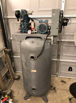
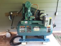
Just picked up my first compressor at an auction this past Saturday! Says it's a 3.5 hp 20 gallon that will do 6.4 cfm at 90 psi. Haven't used it for much other than blowing stuff off and filling tires, but for $130 I was happy.
Changed the oil and cleaned it up a bit since this picture, and fabbed up a hook to mount on my workbench for the air hose.
Sent from my Pixel using Tapatalk


Paperman 2000 CFM at 120 PSI. :thumbup:[/QUOTE said:YOU win !!


Working on some industrial equipment peaked my interest in automating the controls on a compressor.
Working on some industrial equipment peaked my interest in automating the controls on a compressor. On and off just isn’t good enough for me anymore. So while laid up on the couch with a hamstring tear, I came up with this.
I don’t know much about how to draw this stuff, basically just what I found on google pictures, so forgive the crudity/mistakes.
Everything is powered from the breaker box. Line power will also come in as a signal from the light switch (overhead light circuit). This way it will run when I’m there and shut off (mostly) while I’m gone.
My idea is to use a digital pressure switch with 2 outputs to control the compressor, cooler fan, and a head pressure relief valve on one output. The tank drain will be an open/closed valve of some sort with a timer circuit on output 2.
Output 2 won’t come on untill the compressor cycles to full pressure, and will latch the power for the drain timer untill the tank pressure drops below a certain amount. This way the tank will continue to drain while I’m gone and give the compressed air time to condense... and drain.
When I turn on the lights again, the compressor won’t run untill I hit the start button which will turn on the first contractor and the 24v power supply for the relays and stuff.
So... whatcha think?
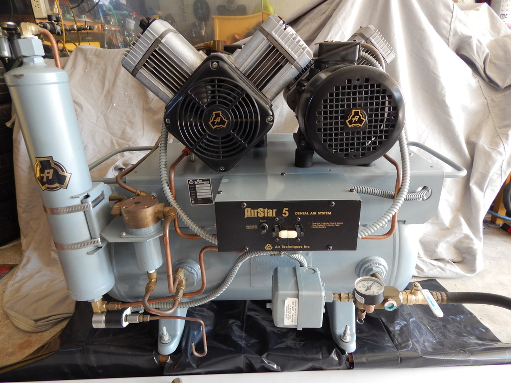
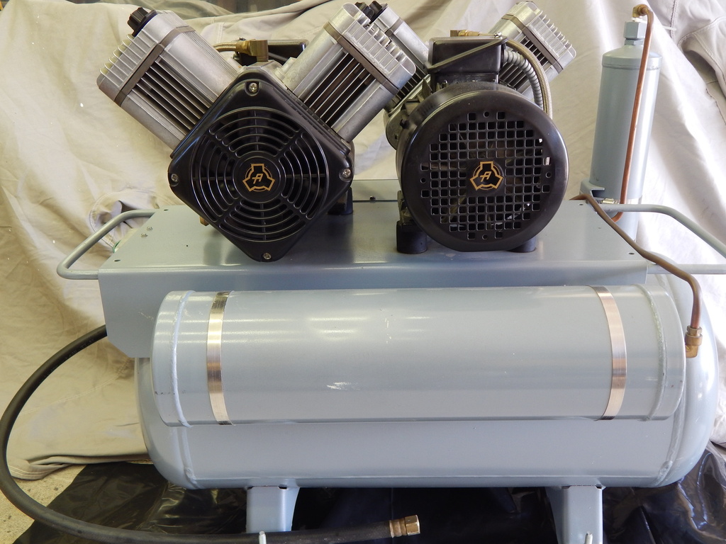
Also, this is what it looks like put together. Cable management needs work, but I’m learning.
Still figuring out how I’m going to attach it, but this spot looks promising. Right under the cooler/fan.


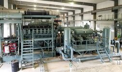
CAT G3616A4 driving Ariel KBZ/6 3-stage
I find such over complication totally unnecessary, interesting, and just plain cool.
Hope you're adding some LED digital pressure and temp. displays...
You should also consider a VFD for soft starts and slow cool down ramping.
what cooler/fan is that you have there?


The people at Ariel are a great group. They are so nice to deal with. How are their machines?Little 5,000hp unit we have in a shed out back
CAT G3616A4 driving Ariel KBZ/6 3-stage
Actually have 4 of these running and not exactly out back, lol. They move 300 mmscf/day of 1450 BTU NG combined.
Sorry, saw the thread title and had to show off my compression!
Sent from my SM-G950U using Tapatalk
Fantastic company, their compressors are the gold standard in their segment. Still a family run business.The people at Ariel are a great group. They are so nice to deal with. How are their machines?
Sent from my BBB100-1 using Tapatalk
FWIW, I used to do everything unnecessarily complex as well, my ample industrial junk bin a wealth of solutions chasing after nonexistent problems.
I put this together for my 325, I suffer from the same issue....
https://www.garagejournal.com/forum/...ressor+control


Scored this setup off CL earlier this year, into it all for about $550 total. 3Z181 (Champion R15 pump) with brand new 5 hp Baldor motor, and separate purchase of a 200psi 30 gal tank with 15CFM dryer mounted to it. Finally back together and heard it all run for the first time. Condensate free air from the dryer! Question - in this vid you can sort of hear the hollow sound the compressor makes somewhat intermittently. Is this something I should be concerned about? Never ran a compressor this big, or with the K&n filter (original was broken). Compressor is rated at 17.3 CFM and puts out 17.1 up to current cut off at 120 PSI. No need for 175 psi air yet for my applications. Vid -
Pics-


Also made a belt tensioner -

Used the advanced setting auto add for pics not sure why they aren't showing up ����****
Scored this setup off CL earlier this year, into it all for about $550 total. 3Z181 (Champion R15 pump) with brand new 5 hp Baldor motor, and separate purchase of a 200psi 30 gal tank with 15CFM dryer mounted to it. Finally back together and heard it all run for the first time. Condensate free air from the dryer! Question - in this vid you can sort of hear the hollow sound the compressor makes somewhat intermittently. Is this something I should be concerned about? Never ran a compressor this big, or with the K&n filter (original was broken). Compressor is rated at 17.3 CFM and puts out 17.1 up to current cut off at 120 PSI. No need for 175 psi air yet for my applications. Vid -
Think I got all the pics and vid to work now from CPU. Any video input on the echoing noise?
I have an old Saylor Beall that makes a similar sound. At the flywheel end I can see the shaft moving in the axial direction from what appears to be excessive thrust clearance. When the unit is not running I can manually push/pull the flywheel fore/aft and create the same sound that occurs when running. Mine has been that way for about 30 years now.
Any details on your dryer?

This is me too, the first I built of anything,,, 2 x as big, 2x as heavy and cost 2x as much as it needed.FWIW, I used to do everything unnecessarily complex as well, my ample industrial junk bin a wealth of solutions chasing after nonexistent problems. As I got older I had to occasionally repair the abominations of my prior genius and often could not recall how the damned things were supposed to function in the first place, usually having to reverse engineer my own creation and then re-engineer it with a few decades of enhanced wisdom and experience, usually cutting the component count in half while doubling the reliability and preserving or increasing the functionality. For protection from future repeat performances I have also learned to put schematics in zip-lock bags and stuff them in the enclosures.