To avoid these ads, REGISTER NOW!

Craftsman Drill Press

To avoid these ads, REGISTER NOW!
OP
F

FrankLee

Well-known member
Joined
Sep 13, 2010
Messages
3,546
Location
seMI, 48317
DP#152 - Part 8.1, The Head Frame

Like the other cast iron parts of this machine, the head frame was dirty and mild to moderately rusted.
full
full
full

The first step was a scrubbing with Grez-Off.
full
full
full
full

To clean up some of the rust, I have another weapon in my arsenal; liquid Barkeeper's Friend. BF contains oxalic acid which, like citric acid, will remove some of the lighter rust on painted surfaces. Apply it with a small scrub brush, let it sit for a while, scrub and rinse. Notice the BF will turn brownish when working.
full
full
full

This needed a second application. I wrapped it in plastic so it wouldn't dry out and let it sit for another 20 minutes. Then another scrub and rinse. It's still not perfect, but it's much better.
full
full
full

Barkeeper's Friend works well, but if there is too much rust, you'll get spots of bare cast iron.
 
Last edited:

SMOKEYBEAR

Well-known member
Joined
Jan 3, 2016
Messages
447
Base cover to keep debris out from under it, snagged an orange handle Craftsman torx driver off of ebay. There were screw driver sets and singles, this one was the least expensive. Didn't know such a thing existed until I started searched for orange and black handle screw drivers.
 

Attachments

  • HDDP5.jpg
    HDDP5.jpg
    148.8 KB · Views: 14
  • HDDP6.jpg
    HDDP6.jpg
    62.6 KB · Views: 16
OP
F

FrankLee

Well-known member
Joined
Sep 13, 2010
Messages
3,546
Location
seMI, 48317
DP#152 - Part 8.2

The next step is to clean out all the bores. I use a variety tube brushes and steel wool for the column bores.
full
full
full
full

full
full
full
full

Then, run taps through all the threaded holes.
full
full
full

I also drill (#29) and tap the trim panel mounting holes for an 8-32 machine screw. Craftsman 80s and 100s get a 6-32 screw.
full
full

Finally, blow out the dust, wax and buff. It looks much better with a coat of wax.
full
full
full

I will install the head on the column after all sub-assemblies are installed. I find it much easier to lubricate and assemble the head on the bench.
 
Last edited:
OP
F

FrankLee

Well-known member
Joined
Sep 13, 2010
Messages
3,546
Location
seMI, 48317
When assembling a Craftsman 150 head frame, I install parts and sub-assemblies in this order:
  1. Outer Retaining Ring
  2. Hub, Pinion, Spring & Pin assembly
  3. Quill & Spindle assembly
  4. Quill Lock assembly
  5. Feed Stop assembly
  6. Chuck
  7. Spindle Pulley assembly
  8. Head Trim Panel
Assembling a Craftsman 80 and 100 would be a slightly different sequence.

DP#152 - Part 9, The Outer Retaining Ring

The outer retaining ring is installed in a groove in the 50mm lower bore for the lower spindle pulley bearing. The ring provides a stop for the lower bearing to rest on.

The oe outer retaining ring is a proprietary part. The hooks on the retaining ring are often inconsistent. In the photo on the left below, the hook on the upper right allows needle nose pliers to slip off when compressing the ring. There was no problem installing the lower ring on DP#152.
full
full

Sometimes, I'll file a small flat on both inside ends of the ring with a small triangular file to better define the hook which makes it easier to install.
1780569191768.png
I believe a standard internal retaining ring would fit.
 
Last edited:

Cruzan80

Well-known member
Joined
Jul 22, 2015
Messages
4,161
Location
Denver, CO
Obviously there are a few other modifications on this drill press (switch/cord/motor knobs/etc), but curious if the belt cover is OEM. I looked, and couldn't find a different version for the 150, and kr loomed like they stopped listing the 100 version midway thru production. There appears to be a support bracket for it back by the motor.

This is not mine, but found on FBMP. If it is not OEM, it appears to be well-done or regardless.
 

Attachments

  • Screenshot_2026-06-03-13-35-39-68_3aea4af51f236e4932235fdada7d1643.jpg
    Screenshot_2026-06-03-13-35-39-68_3aea4af51f236e4932235fdada7d1643.jpg
    838.9 KB · Views: 10
OP
F

FrankLee

Well-known member
Joined
Sep 13, 2010
Messages
3,546
Location
seMI, 48317
Obviously there are a few other modifications on this drill press (switch/cord/motor knobs/etc), but curious if the belt cover is OEM. I looked, and couldn't find a different version for the 150, and kr loomed like they stopped listing the 100 version midway thru production. There appears to be a support bracket for it back by the motor.

This is not mine, but found on FBMP. If it is not OEM, it appears to be well-done or regardless.
Not oem, but I agree that it was well done. I believe the oem cover was an option from only '53 to '56.
Please post a link to the FB listing.
 
To avoid these ads, REGISTER NOW!
OP
F

FrankLee

Well-known member
Joined
Sep 13, 2010
Messages
3,546
Location
seMI, 48317
DP#152 - Part 10.1, The Hub, Pinion, Spring & Pin Assembly

full
full


Dismantling

Tye first step of dismantling the assembly is to remove the fiber thrust washer. They're somewhat fragile and sometimes missing.
full

Next is pin removal. The pin is 9/32" diameter by 1-1/2" long. The pin has straight knurls 3/8" long on one end to ensure a tight fit in the hub and pinion. You need to identify which end has the knurling and drive out the pin from the non-knurled end. You may be able to see witness marks on the hub. I also use a dental pick to help identify the knurling end. In this case, I could not. I had to punch the pin out a bit to figure that out.
full
full

full
full
full

full
full

In part 1. I mentioned that the previous own replaced the spring. He drove the pin out from the knurled end which flattened them.
full

With the pin removed, pull the spring out of the pinion shaft and remove the hub. This hub came off easily. The hub is often tight on the shaft. from dried grease. I've had success using a torch to gently heat the overlapping hub portion.
full
full
 
Last edited:
OP
F

FrankLee

Well-known member
Joined
Sep 13, 2010
Messages
3,546
Location
seMI, 48317
DP#152 - Part 10.2

Cleaning

The first step is to clean the steel parts with lacquer thinner in the sonic cleaner.
full
full
full

While that was cooking, I cleaned the hub with Grez-Off.
full
full
full
full

There was a hard film on the chrome, so I proceeded with cleaner wax and #0000 steel wool. This works great, but not too much pressure.
full
full

Finally, i ran a 1/2-13 tap through the rod holes to clean the female threads. This completes the hub.
full

Back to the pinion and spring... Both were wire wheeled along with the pin.
full
full
full

full
full
full

I wasn't satisfied with just wire wheeling the pinion shaft, so I soaked it in citric acid and wet sanded with 1200 grit paper.
full
full

full
 
Last edited:
OP
F

FrankLee

Well-known member
Joined
Sep 13, 2010
Messages
3,546
Location
seMI, 48317
DP#152 - Part 10.3

Assembly

My swag is that during the manufacturing process, the hole for the pin was bored with the pinion shaft inserted in the hub. Rarely will the holes line up when swapping hubs or pinions from another machine. The through holes will only line up one way.

In the photo on the left, the pin is inserted from below, but the holes on the top are not even close in alignment. In the center photo, I am applying a bit of anti-seize in the hub. The photo on the right is with the pinion shaft rotated 180 degrees in the hub with the pin bores aligned correctly.
full
full
full


Here, I am applying a bead of Super Lube oil along the length of the spring barrel. The spring is inserted into the pinion shaft with the loop of the spring aligned with the pin bore. The non-knurled end of the pin was loosely inserted which captured the loop of the spring. Because the knurls of this pin were mashed, I added a drop of low-strength thread locker to the end of the pin.
full
full
full
full


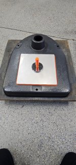
With the assembly back in the jig, the pin was driven into the hub and pinion shaft.
full
full

The Hub, Pinion, Spring & Pin assembly is ready to install into the head frame.
 
OP
F

FrankLee

Well-known member
Joined
Sep 13, 2010
Messages
3,546
Location
seMI, 48317
DP#152 - Part 10.4

Installation

I applied a small dab of Super Lube grease to the edge of the hub for the fiber thrust washer. This acts as a glue to hold the washer during assembly and to lubricate the washer between the hub and head casting during quill feed.
full
full

Then, I inserted the shim into the spring.
full

Next, I sparingly lubricated the pinion shaft and it's bore in the head casting with Super Lube grease. The pinion gear was generously lubricated. I pressed the grease into the teeth of the pinion gear with my finger.
full
full
full

I inserted the assembly into the head casting, attached the spring loop onto the roll pin and removed the shim.
full
full
full

Installation is complete.
full

 
Last edited:
To avoid these ads, REGISTER NOW!
Top Bottom