SMOKEYBEAR
Well-known member
- Joined
- Jan 3, 2016
- Messages
- 474


Not oem, but I agree that it was well done. I believe the oem cover was an option from only '53 to '56.Obviously there are a few other modifications on this drill press (switch/cord/motor knobs/etc), but curious if the belt cover is OEM. I looked, and couldn't find a different version for the 150, and kr loomed like they stopped listing the 100 version midway thru production. There appears to be a support bracket for it back by the motor.
This is not mine, but found on FBMP. If it is not OEM, it appears to be well-done or regardless.


I wish I'd known about your freezer and lightbulb trick. One of my 2 rebuilds gave me a lot of trouble getting those bearings on. Thanks again for good advise.DP#152 - Part 11.3
Assembly
The first step is to heat the bearing. Five minutes on the light bulb is enough.
Next, retrieve the spindle from the freezer and slide the heated bearing onto the frozen spindle.
Install the quill onto the lower bearing.
Heat the upper bearing and slide it onto the spindle. It may not slide all the way into the quill.
Fully seat the bearing into the quill with a pipe on the inner race of the bearing.
Next, install the steel spindle washer and the rubber spindle washer.
Slide the collar onto the spindle with the set screw hole over the divot in the spindle. Then, install and tighten the set screw. You should feel the rubber washer compress slightly as the point of the set screw finds the center of the divot. This is preloading the bearings.
Rinse the spindle collar and set screw in acetone to remove any trace of oil and let dry. Apply a dot of thread locker in the internal threads of the collar and on the external threads of the set screw.
Next, clamp the splines of the spindle into a vise and install the quill gasket (bumper) onto the lower quill.
Clamp the ends of the quill retaining ring into vise grips. With spreading piers, splay open the retaining ring enough to slide it onto the quill and into its groove.
Assembly is complete.
DP#152 - Part 11.4
Installation
The first step is to apply a generous bead of Super Lube grease along the gear rack. I apply it on the side of the gear rack where the pinion gear intersects with the gear rack. Spread it into the teeth with a finger.
Then, spread a thin layer of grease onto the outside of the quill.
Next, draw out the hub/pinion with one hand and fully insert the quill/spindle assembly into the head casting. Turn the quill if necessary to allow the pinion gear to mesh with the gear rack. Allow the hub/pinion to retract back into the head casting.
Turn the hub/pinion back and forth a few times to verify that the quill moves smoothly in the head casting. Installation is complete. Spring tensioning will come later.
It probably works more than 90% of the time. It works great for motors too.I wish I'd known about your freezer and lightbulb trick. One of my 2 rebuilds gave me a lot of trouble getting those bearings on. Thanks again for good advise.
 www.garagejournal.com


That could work, but whatever is used with that collar, except a tight set screw, I think it would slide on the rod during a high-torque feed. I've seen steel 1/4-28 bolts used in oe collars. They were tightened on the rod flats and caused vertical scars.Frank, what about a small brass slug under the existing set screw? Not sire how much room you have to work with.
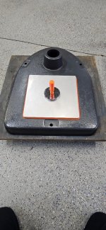
When I assembled my 150 I also noticed how recessed the quill lock cylinder was, and it didn't "match" the head lock cylinder. It bugged me enough that I found a shiny washer and epoxied it to the end of the cylinder to make it look better.DP#152 - Part 12.1, The Quill Lock assembly
Dismantling
There's not much to it... remove the set screw for the handle with a 3/32" hex key and remove the handle from the lock bolt hex head.
Remove the threaded lock cylinder and slide off the sleeve cylinder. The washer is not in the parts list, but likely added to space the handle away from head casting.
DP#152 - Part 12.2
Cleaning
All parts were cleaned in the sonic cleaner.
All steel parts were then soaked in citric acid.
All parts were wire wheeled. The chrome handle was gently wheeled with a 0.004" fine wire wheel.
The inside of the cylinders were cleaned with a tube brush. A tap was run through the lock cylinder.
DP#152 - Part 12.3
Assembly and Installation
Sparingly lubricate the lock bores with Super Lube grease.
Apply a drop of oil on the bolt shoulder for the sleeve cylinder and a drop on the threads for the lock cylinder. Slide the spacer washer and sleeve cylinder onto the lock bolt.
Insert the threaded lock cylinder into the right side of the head casting and the bolt with sleeve cylinder into the left side.
Gently tighten the quill lock bolt and place the lock handle on the bolt head. I like the lock handle in the 1 o'clock to 4 o'clock position. When unlocked, the handle will hang at the 6 o'clock position. Install and tighten the set screw. The quill lock is complete.
I never noticed this before. On this 150, notice how deep the lock cylinder is into the head casting in the photo on the left. The center photo is my keeper 100. The head castings are slightly different around the quill lock. This would also explain the spacer washer under the lock bolt head.


No, the original collar was missing and replaced by that one-piece collar.So this one does not use double nuts as a stop "collar"?

 drive.google.com


So no grease, just oil?DP#152 - Part 14.3
Assembly
I first apply a drop of Super Lube oil in each upper and each lower jaw bore segment.
Then, I inserted the jaws into their original locations.
With the chuck standing upright on the bench, the jaws were pushed down flush with the nose.
I added a drop of oil to the threads in the split nut and installed both halves.
Then, holding the split nut together, I turned the chuck to extended the jaws for sleeve installation.
Next, I slipped on the sleeve and press it down to hold the nut halves in place.
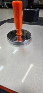
The chuck was carefully placed in the puller and the sleeve was pressed on.
The chuck was removed from the puller and tested by fully extending and fully retracting the jaws. It operates so smoothly!


So no grease, just oil?
I prefer oil. Grease is not wrong.

I'd definitely stick with oil on the jaws, a light grease like super lube on the treads is fine IMO.
You haven't got to the Key yet but I strongly recommend adding a handle to finish that job:
Custom Chuck Key Handle
My custom key handle: