
You are using an out of date browser. It may not display this or other websites correctly.
You should upgrade or use an alternative browser.
You should upgrade or use an alternative browser.
Craftsman Drill Press
- Thread starter FrankLee
- Start date
I cleaned everything back up and took a closer look. The nut seems to mate okay. Does it look like the first teeth on the left side on the top and middle jaws are broken? I know it’s hard to see but there’s only a sliver of metal on the top one which would be #1.Are the jaws in the same relative positions as they were before disassembly?
Do the split nut halves mate together properly?
In photo 3337, the middle jaw, is that grease on the far right tooth or is that a defect on the tooth?
Have you tried tightening with the key?
So if that’s the case, does Jacobs still sell a repair kit for a 633C?

Attachments


Those look normal to me. I have the same picture:I cleaned everything back up and took a closer look. The nut seems to mate okay. Does it look like the first teeth on the left side on the top and middle jaws are broken? I know it’s hard to see but there’s only a sliver of metal on the top one which would be #1.
So if that’s the case, does Jacobs still sell a repair kit for a 633C?

What does the other side look like... the bit contact ridges?
Here’s the other sideThose look normal to me. I have the same picture:
What does the other side look like... the bit contact ridges?
Attachments

Thanks.
Except for the very ends, those look pretty good.
Here are the repair instructions from Jacobs. It shows how to identify the jaw number. I would try to reinstall each jaw in the same position they came from. Then reassemble.
I also prefer Super Lube oil during reassembly... sparingly just a dot for each jaw friction point (six total), in each half of the split nut, on the body for the split nut friction and on each end of the sleeve against the chuck body. IMO, less is more.
Ok, so when I dismantle a chuck, after I extract each jaw, I hit the inside ends on the grinder to match their numbered location. That is, extract number 1 jaw and it gets one hit, extract number 2 jaw and it gets two hits and extract number 3 jaw and it gets none.
This has always been a very easy way for me to keep them organized. I prefer to insert them into their original locations.

Of course, I have forgotten to mark them on several occasions. Then, during assembly, when I inserted them and they didn't line up, I extracted, rearranged and tried again until they did line up. I never referenced that Jacobs diagram in the link above to figure it out.
I currently have three spare sets of jaws and split nuts from fubar chucks. Because of my post above, I decided to reference that illustration to identify each of my spare sets. I could not identify any of my jaws to that illustration!
Has anyone been able to successfully identify each jaw number using that illustration?
Does this illustration not apply to early chucks?

I don't think any of mine resemble any from the illustration.


This has always been a very easy way for me to keep them organized. I prefer to insert them into their original locations.
Of course, I have forgotten to mark them on several occasions. Then, during assembly, when I inserted them and they didn't line up, I extracted, rearranged and tried again until they did line up. I never referenced that Jacobs diagram in the link above to figure it out.
I currently have three spare sets of jaws and split nuts from fubar chucks. Because of my post above, I decided to reference that illustration to identify each of my spare sets. I could not identify any of my jaws to that illustration!
Has anyone been able to successfully identify each jaw number using that illustration?
Does this illustration not apply to early chucks?
I don't think any of mine resemble any from the illustration.
Last edited:
Sorry for the delay in reply. My darn day job gets in the way of my hobbies.
I soaked everything overnight in lacquer thinner, followed your instructions above and resembled in just about every possible position. The original lineup in 1,2, and 3 slots worked the best, but there’s still a small gap. I can live with that for the time being.
A couple of things, there’s some slight burs on the body and the jaws on 1 & 2 twist as the move downward. A jaw inserted in 3 remains flat all the way down. I’m wondering if that has any effect?
Attachments

That doesn't look too bad to me.A couple of things, there’s some slight burs on the body and the jaws on 1 & 2 twist as the move downward. A jaw inserted in 3 remains flat all the way down. I’m wondering if that has any effect?
In the past, I have had issues with the jaw bores at the nose of the body. A po had struck the nose body with a hammer or something and there was slight mushrooming inward on the bores. I used a dremel with a stone bit to clean that up.
Does that gap close when you tighten with the chuck key?
The only other thing I can suggest is that if you remove the sleeve again, insert each jaw individually with the split nut and retract and extend just the one jaw using just the split nut. See if you notice which jaws snags and where.
This information sure was helpful...This is what the gears "should" look like. The gear on the left with the long bushing rides over the top of the shaft. The gear to the right is actually pinned to the shaft that connects to the handle. You can see the hole where the pin is in. Just below that is the actual bottom of the gear. (Lift #4 pics)
This is all I am left with. This is the bushing and right at the top edge the pot metal gear sheared right off. I need this bushing because it is keyed inside. At the bottom of this bushing you will note a scar from a set screw.
That scar is caused from the collar set screw that secures it under the gearbox. You can see the bushing extends from below the gearbox, and then that collar is raised up and screwed down onto it.
The top of the gear should look like this.
So the trick will be, trying to mesh the two gears perfectly otherwise they won't really turn.


And thanks to Hoorn, Frank Lee, 11b30b4 for all the detailed info...
Special thanks to 11b30b4 for the recent 3 videos on the Atlas table & Head lift accessory...
How did Atlas market this item... I noticed on Vintage Machinery, it seems to be predominately on Atlas and Craftsman presses...
I may have also noticed it being used on a few Delta Rockwell presses... Was this a catalogue item Atlas marketed towards any DP with 2-3/4" columns?
Mine arrived today in a green color... And pulling the crank cover off, I noticed a few things... The internal surface of the crank plate is painted green... Both gears are in pristine condition... The crank gear is Zymak... The ACME gear is steel (magnetic)...
Looking closely, the castings don't appear to have seen a repaint... I'm curious as to the green paint color... The two previous colors reported have been dark and light gray... I'm reluctant to pull the Patent plate to see what color might be underneath...
I'm not even sure if this unit has even seen any actual use... The internal surfaces seem very clean...
I paid $150.00 for the lift and I was hopeful the gears weren't trashed...
The only items missing are the two lock handles, which I'll need to acquire...
I have a benchtop Craftsman 150 DP and a Delta DP220 floor model... I'd really like to see this mounted on the Delta...
My plans are to clean out the old grease and reassemble with new lube, and pretty much leave the paint undisturbed...
Any ideas about the origin of the green color?


Glad to help.This information sure was helpful...
And thanks to Hoorn, Frank Lee, 11b30b4 for all the detailed info...
Jeff and Hoorn did a very nice job on those videos!Special thanks to 11b30b4 for the recent 3 videos on the Atlas table & Head lift accessory...
I've never seen any marketing for these other than in Atlas and Craftsman catalogs. I did sell two to the same guy for his Delta machines.How did Atlas market this item... I noticed on Vintage Machinery, it seems to be predominately on Atlas and Craftsman presses...
I may have also noticed it being used on a few Delta Rockwell presses... Was this a catalogue item Atlas marketed towards any DP with 2-3/4" columns?
I don't believe the green paint is original. Take a close look around the edges of the patent plate. I've never seen the inside painted.Mine arrived today in a green color... And pulling the crank cover off, I noticed a few things... The internal surface of the crank plate is painted green... Both gears are in pristine condition... The crank gear is Zymak... The ACME gear is steel (magnetic)...
Looking closely, the castings don't appear to have seen a repaint... I'm curious as to the green paint color... The two previous colors reported have been dark and light gray...
It's really not difficult to remove when using the right technique. On the last few of these I had, I drilled and tapped those patent plate mounting holes for 4-40 screws.I'm reluctant to pull the Patent plate to see what color might be underneath...
https://www.garagejournal.com/forum...drill-press-restoration.528487/#post-10596980
The clean inside is another clue that it was repainted. Usually the original grease is dried out and nasty.I'm not even sure if this unit has even seen any actual use... The internal surfaces seem very clean...
That was a very good deal!I paid $150.00 for the lift and I was hopeful the gears weren't trashed...
I don't have any lock cylinders, but I do have handles only.The only items missing are the two lock handles, which I'll need to acquire...
https://www.garagejournal.com/forum...-drill-press-parts-more.474833/#post-10334440
If you also need cylinders, look for the steel version in lieu of the zamac with separate nut. This would match your 150:
https://www.ebay.com/itm/166606069342
I don't recall ever seeing that shade of green anywhere.I have a benchtop Craftsman 150 DP and a Delta DP220 floor model... I'd really like to see this mounted on the Delta...
My plans are to clean out the old grease and reassemble with new lube, and pretty much leave the paint undisturbed...
Any ideas about the origin of the green color?
Last edited:
Hoorn
Well-known member
@Snip's 100% that green paint was put on by a previous owner. You can see on the collar edge that receives the cover plate green paint smudges.
It would be a good idea to remount the "Nice" thrust bearing mounted on the acme threaded shaft to the outside top of the collar.
Post in thread 'Craftsman Drill Press' https://www.garagejournal.com/forum/threads/craftsman-drill-press.227480/post-9564994
It would be a good idea to remount the "Nice" thrust bearing mounted on the acme threaded shaft to the outside top of the collar.
Post in thread 'Craftsman Drill Press' https://www.garagejournal.com/forum/threads/craftsman-drill-press.227480/post-9564994
Frank Lee referenced an additional YT video on your channel that I missed... Just now found it... A most excellent presentation by you and Hoorn...Snips, congratulation and 150 is a great price IMO. thanks for the mention but Hoorn and FrankLee do all the heavy lifting, I just cobble stuff together and slap a video on YT.
@Hoorn 100% that green paint was put on by a previous owner. You can see on the collar edge that receives the cover plate green paint smudges.
Based on this info, I plan to remove all of the existing green paint and go with the dark gray to match the color on my Delta Rockwell...
It deserves a complete teardown... I'll also reposition the Nice thrust bearing, suggested by you and Frank Lee... Makes perfect sense...
Thanks all...
Your YT videos have been great resource with my rebuilds... Keep up the good work...Snips, congratulation and 150 is a great price IMO. thanks for the mention but Hoorn and FrankLee do all the heavy lifting, I just cobble stuff together and slap a video on YT.
Hoorn and FrankLee have been exceedingly helpful with their knowledge on everything Craftsman and Delta Rockwell...
Outlawmws
Well-known member
Very nice score Snips!
I brought this one home this afternoon, DP#139, a Craftsman model 101.03662.
The alfa-class belt/pulley covers are always cool.
The Head & Table Lift is interesting. The miter gears are both zamac and in great shape. Oddly, there is no patent plate.
The blue paint on the head is original. The table and base were repainted gray.

The alfa-class belt/pulley covers are always cool.
The Head & Table Lift is interesting. The miter gears are both zamac and in great shape. Oddly, there is no patent plate.
The blue paint on the head is original. The table and base were repainted gray.
Hoorn
Well-known member
An outstanding example, well preserved 1940s Craftsman blue. From the front, motor looks like it's in decent shape as well.
The blue paint is plenty scratched and nicked up. The spring looks like it was either replaced, wound clockwise at some time or both. It was detached from the pinion shaft.An outstanding example, well preserved 1940s Craftsman blue. From the front, motor looks like it's in decent shape as well.
The motor is a model 115.5764, 1/2 hp. It is typically loud and in dire need of a new cord. It was not connected to the switch in the head casting. I'm not familiar with the date code format of these early Craftsman motors; " E 1 1 ". First week of May 1941, maybe?
Last edited:
Outlawmws
Well-known member
Awesome find Frank!
Does it have the third puley?
Does it have the third puley?
y'sguy
Well-known member
excellent score, Frank.
Case in point.I've never seen the inside painted.
The clean inside is another clue that it was repainted. Usually the original grease is dried out and nasty.I'm not even sure if this unit has even seen any actual use... The internal surfaces seem very clean...

This will require some extra work.

A few minutes with a couple pair of needle nose pliers fixed that.The spring looks like it was either replaced, wound clockwise at some time or both. It was detached from the pinion shaft.


No, unfortunately.Does it have the third puley?
I really like these old lamp sockets... especially with the 90 degree shades. The sockets are generally assembled with machine screws and are relatively easy to dismantle, clean and adjust. This one may take an extra bit of work.


Uggg... That's going to be fun to correct...This will require some extra work.
I wonder if the last few shaft threads were stripped and this was done to make it work???
Will like to see your repair...
Hoorn
Well-known member
I have been refreshing a 1950s 12-in Atlas made Craftsman lathe, and while sharing images with a friend learned a dirty little secret.

After removing the carriage apron to inspect/clean the carriage gears, I noted a similarity with two gears to the Atlas head and table lift.

These gears, usually sold on eBay for the Craftsman/Atlas 12-in lathe apron, are a direct drop in replacement for chewed up lift gears. The 3/4" lead screw on these lathes rides through the horizontal gear which is keyed -just as the threaded rod does on the lift.
I have replaced missing lift gears with McMaster-Carr steel gears, but this process required lengthy modifications. If a lift required replacement gears, grabbing these OEM gears off eBay is a much better solution. A search using "Atlas Craftsman lathe apron bevel gears" should bring up several offerings, plus reproductions.
After removing the carriage apron to inspect/clean the carriage gears, I noted a similarity with two gears to the Atlas head and table lift.
These gears, usually sold on eBay for the Craftsman/Atlas 12-in lathe apron, are a direct drop in replacement for chewed up lift gears. The 3/4" lead screw on these lathes rides through the horizontal gear which is keyed -just as the threaded rod does on the lift.
I have replaced missing lift gears with McMaster-Carr steel gears, but this process required lengthy modifications. If a lift required replacement gears, grabbing these OEM gears off eBay is a much better solution. A search using "Atlas Craftsman lathe apron bevel gears" should bring up several offerings, plus reproductions.
Hoorn
Well-known member
Thank you FrankLee, that beveled gear even has the correct bushing on it to use with the lift.
Hoorn
Well-known member
Just to point out how prevalent these are on eBay, there are even reproductions made of ABS.

While the ABS would effectively move the carriage back and forth, I wonder how it would hold up lifting a table with a rotary vice attachment. At any rate, we now have options.
While the ABS would effectively move the carriage back and forth, I wonder how it would hold up lifting a table with a rotary vice attachment. At any rate, we now have options.
This will require some extra work.
Uggg... That's going to be fun to correct...
I wonder if the last few shaft threads were stripped and this was done to make it work???
Will like to see your repair...
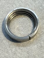
I got lucky.
After loosening the jam nuts from each other, the upper nut came off without any resistance.


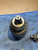
Hello guys! I picked up a 150 a few weeks back that I’m in the process of cleaning up and refreshing. It has a Jacob’s 633C chuck that I’m having some trouble getting off the quill. The chuck key isn’t cutting it for removal of the collar so I picked up a spanner after the suggestion from JeffsShop on YouTube (also directed me here for some input). I have to file down the pin to fit the collar hole better but before cranking on it on wanted to get some opinions here. Was able to wrench the key pretty hard and the chuck just isn’t moving like at all, solid as rock wall. I have a hex key in the chuck and have that clamped into a vise. In the pictures I’m showing the collar at both ends of where it’ll travel with the force I’m using with just the key. Thanks for any input!
Attachments
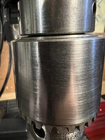


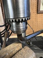

A couple things...Hello guys! I picked up a 150 a few weeks back that I’m in the process of cleaning up and refreshing. It has a Jacob’s 633C chuck that I’m having some trouble getting off the quill. The chuck key isn’t cutting it for removal of the collar so I picked up a spanner after the suggestion from JeffsShop on YouTube (also directed me here for some input). I have to file down the pin to fit the collar hole better but before cranking on it on wanted to get some opinions here. Was able to wrench the key pretty hard and the chuck just isn’t moving like at all, solid as rock wall. I have a hex key in the chuck and have that clamped into a vise. In the pictures I’m showing the collar at both ends of where it’ll travel with the force I’m using with just the key. Thanks for any input!
If you're using the turned-down end of the chuck key, yeah, that rarely works.
Sometimes it takes considerable force to remove the chuck. I prefer to remove the quill/spindle assembly from the head casting and use a vise mounted to a bench. IMO, it's much easier. I also made a longer pin spanner to get more leverage.
https://www.garagejournal.com/forum...keys-etc-1946-1984.489080/page-6#post-9869508


Also, sometimes a previous owner will use a retaining compound on the taper to attach the chuck. Those are a pita and usually require heat to remove.
Last edited:
Ok so it really is just a matter of force? Maybe heat…. JeffsShop mentioned being careful not to strip the threads on the retaining collar so I just wanted to make sure once I get the pin in my spanner filed down to size I didn’t rip the threads apart. I can pull it out of the vise. That’s how I initially started but it seemed like it might be less cumbersome in the machine. I hadn’t really attempted the removal in the machine yet as the key seemed useless. I just got a spanner the other day and hadn’t had time to fiddle yet. The chuck binds a bit midway so I’m hoping can sort that out once I get the dang thing out. I am a bit nervous about pulling it off. Currently it has very little run out, I fear I’ll add that. lol.A couple things...
If you're using the turned-down end of the chuck key, yeah, that rarely works.
Sometimes it takes considerable force to remove the chuck. I prefer to remove the quill/spindle assembly from the head casting and use a vise mounted to a bench. IMO, it's much easier. I also made a longer pin spanner to get more leverage.
https://www.garagejournal.com/forum...keys-etc-1946-1984.489080/page-6#post-9869508
Also, sometimes a previous owner will use a retaining compound on the taper to attach the chuck. Those are a pita and usually require heat to remove.
Thanks!
The threads can get damaged on the earlier 6A chucks with the separate thrust nut. Wedges should be used for those. The collar on the 633C chuck has more threads than the 6A thrust nut and is designed for chuck removal.Ok so it really is just a matter of force? Maybe heat…. JeffsShop mentioned being careful not to strip the threads on the retaining collar so I just wanted to make sure once I get the pin in my spanner filed down to size I didn’t rip the threads apart. I can pull it out of the vise. That’s how I initially started but it seemed like it might be less cumbersome in the machine. I hadn’t really attempted the removal in the machine yet as the key seemed useless. I just got a spanner the other day and hadn’t had time to fiddle yet. The chuck binds a bit midway so I’m hoping can sort that out once I get the dang thing out. I am a bit nervous about pulling it off. Currently it has very little run out, I fear I’ll add that. lol.
Thanks!


I started on my disassembly of the Atlas lift as well...
I built a non destructive drive screw remover...
It only works if the mfg. used through holes for the drive screws and there is access behind and some room...


Factory light gray was behind the cover, confirming the green paint was not original...

Also noted...
Right image: keyed shaft bevel gear was one piece all steel...
Left image: Crank bevel gear is Zamak pined to a steel shaft...

I built a non destructive drive screw remover...
It only works if the mfg. used through holes for the drive screws and there is access behind and some room...
Factory light gray was behind the cover, confirming the green paint was not original...
Also noted...
Right image: keyed shaft bevel gear was one piece all steel...
Left image: Crank bevel gear is Zamak pined to a steel shaft...
Hoorn
Well-known member
@Snip's very innovative panel screw removal tool for tight areas.
Your keyed shaft metal bevel gear confirms that it was indeed made by Atlas at some point during the manufacturing of these head and table lifts.
I have I had seven lifts run through my workshop and of those, I too also found a metal bevel gear.
.jpg")
Post in thread 'Craftsman Drill Press' https://www.garagejournal.com/forum/threads/craftsman-drill-press.227480/post-9439354
In my case, the hand crank bevel gear was also zamak. Also of note, it was from a lift with original light gray paint as well.
I speculate that later model lifts were having metal keyed shaft bevel gears introduced. Since it's the same part for both tools, either the Craftsman / Atlas lathe apron gears were having occasional failure or the lifts, or both, and Atlas sought to correct this by using stronger material.
Your keyed shaft metal bevel gear confirms that it was indeed made by Atlas at some point during the manufacturing of these head and table lifts.
I have I had seven lifts run through my workshop and of those, I too also found a metal bevel gear.
Post in thread 'Craftsman Drill Press' https://www.garagejournal.com/forum/threads/craftsman-drill-press.227480/post-9439354
In my case, the hand crank bevel gear was also zamak. Also of note, it was from a lift with original light gray paint as well.
I speculate that later model lifts were having metal keyed shaft bevel gears introduced. Since it's the same part for both tools, either the Craftsman / Atlas lathe apron gears were having occasional failure or the lifts, or both, and Atlas sought to correct this by using stronger material.
Excellent solution on the tool!I started on my disassembly of the Atlas lift as well...
I built a non destructive drive screw remover...
It only works if the mfg. used through holes for the drive screws and there is access behind and some room...
Factory light gray was behind the cover, confirming the green paint was not original...
Also noted...
Right image: keyed shaft bevel gear was one piece all steel...
Left image: Crank bevel gear is Zamak pined to a steel shaft...
My lift is #9 and I don't recall what the splined gear material was for the earlier lifts. I'll have to review some photos again. My current lift is clearly from the early '40s.@Snip's very innovative panel screw removal tool for tight areas.
Your keyed shaft metal bevel gear confirms that it was indeed made by Atlas at some point during the manufacturing of these head and table lifts.
I have I had seven lifts run through my workshop and of those, I too also found a metal bevel gear.
My thoughts exactly on the gear failures. IMO, the drill press gears had more stress, especially after A) the columns got rusty and the tables were harder to move, and B) those zamak table lock cylinders stuck to the columns.Post in thread 'Craftsman Drill Press' https://www.garagejournal.com/forum/threads/craftsman-drill-press.227480/post-9439354
In my case, the hand crank bevel gear was also zamak. Also of note, it was from a lift with original light gray paint as well.
I speculate that later model lifts were having metal keyed shaft bevel gears introduced. Since it's the same part for both tools, either the Craftsman / Atlas lathe apron gears were having occasional failure or the lifts, or both, and Atlas sought to correct this by using stronger material.
Based solely on photographs, I believe only two of my nine lifts had a steel miter gear on the splined sleeve; much fewer than I expected.My lift is #9 and I don't recall what the splined gear material was for the earlier lifts. I'll have to review some photos again. My current lift is clearly from the early '40s.
Zamak on the left below, steel on the right.


Also, based on my photos and @Hoorn's miter gear rebuild posts, I observed that there are at least three different styles of the splined sleeved miter gear; all steel, all zamak and zamak gear on a steel sleeve.
4/1/2024
Lift cleanup continues...


Grez-Off is awesome!

Last edited:
Hoorn
Well-known member
We can now obviously add a third color to the head and table lift, the Long C era royal blue to accompany the light and dark gray. A beautiful color, you brought out all of its brilliance. In addition to your noted steel / zamak miter gear differences.
No patent badge / badge on left side / badge on right side.
Solid handle / shaft behind handle knob.
By the way, nine lifts! You've taken the lead and I'll never catch you..
No patent badge / badge on left side / badge on right side.
Solid handle / shaft behind handle knob.
By the way, nine lifts! You've taken the lead and I'll never catch you..