To avoid these ads, REGISTER NOW!

E-tek Restorations: PROJECT THREAD

OP
E

e-tek

Well-known member
Joined
Dec 19, 2007
Messages
10,690
Location
Saskatoon, SK
More time into the 40 Ford hood and front end today:

106_2926.JPG


Not sure why there was this small bit missing from the hood lip, but while I was strengthening the it all I put it back as well:

106_2966.JPG


The front end of the latch plate is a definite weak spot, allowing flex to travel back and along the other arms and then the hood attachment points:

106_2967.JPG


I decided the piece I started making wasn't thick enough (18g?), so I started again, with a new piece (16g?):

106_2971.JPG


Shaped it and added plug weld holes:

106_2974.JPG


Then welded it to the front end to strengthen the mounting point:

106_2978.JPG


Dressed the welds, re-drilled the holes and cut out the center notch:

106_2979.JPG


106_2980.JPG


106_2981.JPG


I trial-fit the piece with just this change and it made a big difference, but I still want to double up the side hood areas where the initial crack was found:

106_2986.JPG


As well, thanks to MP&C for bringing my attention to a fabricator on Metal Meet who built an inner support for the hood nose on his own Ford. This may be my next project.

http://www.metalmeet.com/forum/picture.php?albumid=349&pictureid=9597

picture.php


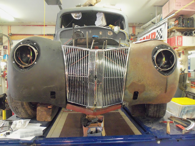
Also test fit the grille pieces to get some measurements:

106_2987.JPG


106_2988.JPG


106_2996.JPG


After this I began working on the gas filler neck. I was just taking some measurements to cut the neck down and the power went out. Someone must have ran into a power pole again (happened a couple months back too). So without electricity I couldn't do much and without lights I couldn't take any photo's - so we took the kids to Mickey Dee's instead...:sad::lol:
 
Last edited:
To avoid these ads, REGISTER NOW!

Kevin54

MEMBER EMERITUS
Joined
Jan 12, 2005
Messages
29,341
Location
Urbana, Ohio
106_2988.JPG


E-Tek.....What's the deal at the bottom of the fenders at the grille area? The driver side fits nice to the grille, but the passenger side doesn't fit too well. Is it the fender or is the grille not setting right?
 
OP
E

e-tek

Well-known member
Joined
Dec 19, 2007
Messages
10,690
Location
Saskatoon, SK
106_2988.JPG


E-Tek.....What's the deal at the bottom of the fenders at the grille area? The driver side fits nice to the grille, but the passenger side doesn't fit too well. Is it the fender or is the grille not setting right?

Hey Kev - Both! The grille pieces are just hanging there in these photo's. I wanted to see how & where they mounted, as well as how close all the other pieces were to each other. I won't be able to mount it all up and do the finishing/gap work until some brackets are found/made for the inner fenders to frame (and also for the top of the rad). As you likely know, these grille pieces will go on and off (they are already off) MANY times before going for paint!
 
OP
E

e-tek

Well-known member
Joined
Dec 19, 2007
Messages
10,690
Location
Saskatoon, SK
Bit of a slow week due to an inner ear infection and bad back - pretty hard to get much done as a dizzy gimp....but after a well-earned roll in the sack last night I was feeling MUCH better today!

Saw these retro cans of WD on the shelf yesterday:

IMG-20121120-00152.jpg


40 Ford original gas filler tube -

106_3005.JPG


Owner has this newer Ford filler neck with anti-splashback and cap-pocket assembly that I'm going to retro-fit into the 40Ford:

106_3004.JPG


Nurse! Tape. Suction. Saw.....

106_3006.JPG


106_3009.JPG


106_3008.JPG


106_3012.JPG


After a few minutes of bending and tweaking to set gaps:

106_3014.JPG


106_3017.JPG


Overhead:

106_3019.JPG


Fitting hood chrome and latch:

106_3024.JPG


106_3024.JPG


106_3025.JPG


Back to the wiring. We all know how important grounds are and how they can **** up hours of troubleshooting...so I bought an engine to frame cable:

106_3026.JPG


And rigged up a short battery to body cable, which will add a redundant ground to the system:

106_3027.JPG


Also grabbed a 12V power source socket to charge whatever is needed. It will likely go in the console.

106_3028.JPG


Behind the dash, things are slowly getting cleaned up, labelled and checked:

106_3029.JPG


106_3031.JPG


There a whack of wires coming from the door opener system that have to be coiled up, tied back and hidden:

106_3030.JPG


Tomorrow it'll be mostly wiring, trying to get it into a "RUN" situation.

Mustang-86-Mustang-ECC-EFI.gif
 

theoldwizard1

Well-known member
Joined
Feb 22, 2011
Messages
43,073
Location
SE MI
A couple of tips on wiring the EEC Harness.

The "inertia switch" is not really required. It was a safety item to cut off power to the fuel pump in an accident. Since most accidents cause the engine to stall, the EEC will turn off the fuel pump anyway. If you do use one, be carefully how you physically mount it. I know of one guy who mounted it too close to where the trunk latch was located and every time he slammed the trunk, the switch would trip !

The item labeled "Idle Speed Sensor" is actually the Idle Air Controller (IAC) or, as I call it the Idle Air Bypass Valve.

Your diagram only shows one connection from the power relay to the EEC, but I am certain there are more than that. Run separate wires from the module to the relay.

Likewise, there are multiple ground pins on the module. Run separate wires from the module to the battery ground post or a junction point close to the battery.

The diagram does not show how the A/C connections are wired. One is somehow connected to the A/C on/off switch (likely after any A/C safety switches). The other somehow control an A/C system cutoff. You could probably ignore these without any problems.

Remember, factory splices only required 2 wraps of bared copper and were cover by a couple of turns of friction tape (you would call that hockey stick tape). The whole harness was covered in either convoluted plastic tubing or non-adhesive PVC electrical tape. Friction tape was used to terminate either the non-adhesive tape or convoluted tubing.

Pack all connectors with silicone dielectric grease.

One more thing. I hate fuse links ! Use a good quality weatherproof inline fuses holder.

images
 
Last edited:
OP
E

e-tek

Well-known member
Joined
Dec 19, 2007
Messages
10,690
Location
Saskatoon, SK
Good timing OldWiz - here's me right now (live action shots from the E-tek Shop!!):

106_3045.JPG


106_3041.JPG


106_3044.JPG


Just finished stripping the harnesseseses.....now I can start whittling them down to what's actually needed and what's (hopefully!) not.

-----> For anyone that has done an EFI engine transplant with the STOCK harness retained and an aftermarket (Painless/IAS) harness inside....see my seperate EFI transplant thread (below) to give advice - rather than get this one WAY muddled. Thanks!!

http://www.garagejournal.com/forum/showthread.php?t=175710
 
OP
E

e-tek

Well-known member
Joined
Dec 19, 2007
Messages
10,690
Location
Saskatoon, SK
After stripping all the tape and corrugated tubing, I could finally see what went were and what color the wires are:

106_3049.JPG


106_3054.JPG


The rest of the afternoon was spent tracing and labeling all the wires and finding where they terminated, plus which pin they originated from on the EEC.

106_3053.JPG


106_3052.JPG


106_3051.JPG


106_3050.JPG


106_3048.JPG


OK - the wiring photo's maybe aren't as exciting as welding and painting, but nothing runs until this part is all sorted out - so onward!
 

HOTFR8

Banned
Joined
Mar 2, 2007
Messages
24,498
Location
Castlemaine, Victoria. The Hot Rod Centre of Austr
What a nightmare that looks to be.

The Auto Elec I use comes on site and does all that for me. When the F4 was done he wired that from scratch in about 8 days and that did not include the sound system. He gave me a wiring diagram and codes for the wires when completed and keeps a record for himself so if I ever have problems he can talk me through it over the phone. I have never used a factory made wire loom and most likely never will.

Keep us informed of your progress and how it all works out.
 

Omphaloskeptic

Well-known member
Joined
Oct 11, 2008
Messages
2,346
Location
Ultima Ratio, Wa.
E-Tek, I'd say that is one daunting task you have begun; good luck!

Hotfr8's comment about a wiring diagram made me wonder if you are creating you own for this beast? I realize you have reference schematics at hand, but would it be helpful to create your own as it applies to this job? I'd be inclined to make some large printouts and use some view foil stock as an overlay to 'create' a schematic as it applies to this installation. Knowing how I can confuse myself with a complicated task, I'd have to resort to using colored grease (?) pencils to keep track of what's done, and what's been modified/deleted/improved. How the devil are you keeping everything straight?
 

theoldwizard1

Well-known member
Joined
Feb 22, 2011
Messages
43,073
Location
SE MI
After stripping all the tape and corrugated tubing, I could finally see what went were and what color the wires are:

106_3049.JPG


OK - the wiring photo's maybe aren't as exciting as welding and painting, but nothing runs until this part is all sorted out - so onward!
You are doing it the right way ! Aftermarket harness for the EEC system are not worth the cost, if you are using the stock PCM and al of the stock sensors and actuator.

I would redo the insulation on splices like the one in the picture with 3M 1755 friction tape or, if you want to be fancy, 3M 130 linerless rubber splicing tape. Don't waste your time with solder or crimp connectors when shortening/lengthening parts of the harness. Strip enough insulation to get 2 full turns of bare copper.

This is best deal I have found on Non-Adhesive Vinyl Harness Tape. Finish with 3M linerless splicing tape.

Ignore A/C connections to the PCM.

Use inline weatherproof fuse holders instead of fusible links.

Run all grounds to a point close to the battery. The PCM housing should be grounded to the chassis via the mounting bracket.


You have a god start ! If you didn't live a million miles from NOWHERE I would be there to give you a hand in exchange for a couple of beers !

EDIT: It is called "convoluted tubing".
 
Last edited:

HOTFR8

Banned
Joined
Mar 2, 2007
Messages
24,498
Location
Castlemaine, Victoria. The Hot Rod Centre of Austr
E-Tek, I'd say that is one daunting task you have begun; good luck!

Hotfr8's comment about a wiring diagram made me wonder if you are creating you own for this beast? I realize you have reference schematics at hand, but would it be helpful to create your own as it applies to this job?

Yes I will add I have a copy as well as the Auto Elec and it has saved the Auto Elec driving to see me and knowing more about what he may have to fix before he gets here.

No hesitation about a daunting task.
 
OP
E

e-tek

Well-known member
Joined
Dec 19, 2007
Messages
10,690
Location
Saskatoon, SK
EDIT: It is called "convoluted tubing".

This is Corrugated tubing:
images


The wiring - now THAT's convoluted....

Kinda like using "wala" instead of "viola".....

Thanks Wiz for the tips - much appreciated. I'll get it done - I didn't spend 4 years in grade 5 for nothing.
 
Last edited:

theoldwizard1

Well-known member
Joined
Feb 22, 2011
Messages
43,073
Location
SE MI
This is Corrugated tubing:
images


The wiring - now THAT's convoluted....

Well, maybe to you ! I spent way too many years staring at those diagrams !!

Results from googling "convoluted tubing" And you should see what is inside the PCM !
 

Attachments

  • Capture.JPG
    Capture.JPG
    113.6 KB · Views: 67

Kevin54

MEMBER EMERITUS
Joined
Jan 12, 2005
Messages
29,341
Location
Urbana, Ohio
con·vo·lute [kon-vuh-loot] Show IPA verb, con·vo·lut·ed, con·vo·lut·ing, adjective.
verb (used with object), verb (used without object)
1.
to coil up; form into a twisted shape.
adjective
2.
rolled up together or with one part over another.
3.
Botany . coiled up longitudinally so that one margin is within the coil and the other without, as the petals of cotton.
Origin:
1690–1700; < Latin convolūtus rolled up, equivalent to convolū- (stem of convolvere to convolve) + -tus past participle suffix

Related forms
con·vo·lute·ly, adverb.
sub·con·vo·lute, adjective.
sub·con·vo·lute·ly, adverb.
un·con·vo·lute, adjective.
un·con·vo·lute·ly, adverb.


cor·ru·gate [kawr-uh-geyt, kor-; kawr-uh-git, -geyt, kor-] Show IPA verb, cor·ru·gat·ed, cor·ru·gat·ing, adjective.
verb (used with object)
1.
to draw or bend into folds or alternate furrows and ridges.
2.
to wrinkle, as the skin or face.
3.
Western U.S. to make irrigation ditches in (a field).

adjective
5.
corrugated; wrinkled; furrowed.
Origin:
1375–1425; late Middle English < Latin corrūgātus past participle of corrūgāre, equivalent to cor- cor- + rūg ( āre ) to wrinkle + -ātus -ate1

Related forms
cor·ru·gat·ed, adjective.
cor·ru·ga·tor, noun.
un·cor·ru·gat·ed, adjective.

Word Origin & History

corrugated
1620s, "wrinkled" (of skin, etc.), pp. adj. from corrugate. Meaning "bent into curves or folds" (of iron, cardboard, etc., for elasticity and strength) is from 1853.

I've always heard it called "corrugated tubing" and not convoluted.

You learn something new on this site every day.
 
OP
E

e-tek

Well-known member
Joined
Dec 19, 2007
Messages
10,690
Location
Saskatoon, SK
Well, maybe to you ! I spent way too many years staring at those diagrams !!

Results from googling "convoluted tubing" And you should see what is inside the PCM !

Sorry - my reply wasn't very clear, I was actually agreeing with you! But now with Kev's input, it seems the terms are near-interchangeable....guess we're both right - and that's rare!! Thanks for your help on this subject tho, it's much appreciated. :thumbup:
 
OP
E

e-tek

Well-known member
Joined
Dec 19, 2007
Messages
10,690
Location
Saskatoon, SK
Just got word that I was chosen to be part of the Dupli-color "Paint Crew" promotion. I already use a lot of their products so I'll be interested in using/testing/reviewing a lot more of them.

dcpc.png
 
To avoid these ads, REGISTER NOW!

Omphaloskeptic

Well-known member
Joined
Oct 11, 2008
Messages
2,346
Location
Ultima Ratio, Wa.
E-Tek,

Dupli-color "Paint Crew"?! Wow, quite the deal; CONGRATULATIONS!

So, how does this work? Do you 12 guys get together for a team meeting, do you get to wear fancy schmancy team uniforms, do you make special appearances and sign autographs on product cans? Most importantly, does the Dupli-Color crew get its own CHEERLEADER SQUAD??? If so, I nominate Mrs. E-Tek as CHEERLEADERLEADER; we already know she would look OUTSTANDING in a short pleated skirt, a tight fuzzy sweater and a set of pom-poms! :drool:

Okay, I'm seeing it now; it's late and the prescription drugs are kicking in. :drunk:

We've seen 'The Dynamic Duo', 'The Three Amigos', 'The Fearsome Foursome', 'The Magnificent Seven', 'Ocean's Eleven', and now we get introduced to 'THE DUPLI-DOZEN'! :lol_hitti

There was 'The Dirty Dozen', but I'm quite sure you and the other 11 "talented individuals" will overshadow any memory of them.

Picture this.....

Twelve "talented individuals" all snazzed out in tailored satin jumpsuits; each done up in a different Day-Glow hue of the Dupli-Color product line. The stage is dark and with a raucous fanfare, twelve individual spots target the twelve "talented individuals" as they ride out on stage on customized Segway scooters painted in the matching metal flake colors of their riders. The Segways are equipped with a dozen cup holders, each one filled with Dupli-Color products chosen by the rider. They wheel out and do a motorized choreography of spinning turns and near-misses as they converge on a shrouded bulk at center stage. The music climaxes and the shroud is whipped up and away to reveal a Rolls-Royce limo, naked metal except for the dull patina of red primer (Dupli-Color, of course). The Segways begin circling the RR in a counter-clockwise fashion and in the background, the audience hears the soft steady chant of the Dupli-Dozen's own cheerleader squad, 'The DUPLIcitys'! The chanting becomes louder, more insistent as the D.D. team converges on the RR. Cans at the ready, they unleash a 'cloud of color' obscuring the limo, and the The DUPLIcitys' voices rise in shrill unison with the battle-cry of the D.D. team, "WOO-WOO, DO THE DO, DO THE DO, DO THE DUPLI-COLOR DO, WOO-WOO.... WOO-WOO....WOO-WOO....DUPLI, DUPLI, DUPLI-COLOR DOO!!!" As the DD riders form up at stage front, and the 'cloud of color' settles, the audience issues rapt oohs and aahs as a brilliant set of hot white floods reveal the Rolls-Royce Limo in all its new-found-spray-can glory. The D.D. team, that elite group of twelve "talented individuals", has taken the R.R. from a lackluster base of primer red to an astounding ascension resulting in a psychedelic palette of plaid! A vision beyond the audiences comprehension, a post-post modern masterpiece on the epitome of the traditional canvas and gilt framed artifact. A Rolls-Royce that could only be envisioned by the LSD ingesting ******* children of Andy Warhol and Queen Victoria.

*** :drink: :canada: :badteeth: :tard: :moon: ***
*** :deathmeta: :eyecrazy: :p :bounce: :Sleep: :ninja: ***

Twelve "talented individuals"​


:lol_hitti Okay E-Tek, the buzz is dwindling; must be time for bed. Sorry for the rambling, and now back to our regularly scheduled thread.....
 
OP
E

e-tek

Well-known member
Joined
Dec 19, 2007
Messages
10,690
Location
Saskatoon, SK
Big weekend at the E-tek shop! Finally got some more work done on my 240Z, plus stripped the top end from the 390FE that will be going in my Galaxie. On the 40Ford, I energized the electrical system by hooking up the battery charger at 2Amps, so I could check circuits without causing any accidental damage - so far so good!

See it all on my blog (of course!!): www.E-tekRestorations.blogspot.com
 
OP
E

e-tek

Well-known member
Joined
Dec 19, 2007
Messages
10,690
Location
Saskatoon, SK
Got this in the mail today from larry_g - very cool. It'll be displayed in my shop in the winter and hang in my 46 Merc truck in the summer.

IMG_0141.JPG


IMG_0143.JPG


IMG_0144.JPG


Lucky for me, the 6V lighter outlet still works in the "Old Man".

IMG00494-20111031-1600-769944.jpg


(*Sincere apologies to lg for the mixup in names....)
 
Last edited:
OP
E

e-tek

Well-known member
Joined
Dec 19, 2007
Messages
10,690
Location
Saskatoon, SK
Shop time today went by fast, but it was mostly electrical again - other than splicing together custom rad hoses - which had to be fairly exact to get around the obstacles

117_3174.JPG


.....and squeeze into the tight spaces available...sometimes I don't know how mechanics get their hands in these spaces!!

117_3176.JPG


The engine and car has power, windows go up and down, alternator hums, fuel pump runs....so things are looking good that way. Also had to make a pin plug for the brake switch that's located between the frame rails -

117_3168.JPG
 
Last edited:
OP
E

e-tek

Well-known member
Joined
Dec 19, 2007
Messages
10,690
Location
Saskatoon, SK
Got quite the variety of things accomplished this weekend! Here's a taste, but the details are in the my blog.

Got the Holley 4 bbl cleaned up for the rebuild:

119_3211.JPG


Cleaned up a bunch of flathead parts, some that will go back in the two engines that are going to the machine shop this week - and others that will go on a display engine. I've decided I'd rather have an engine on a stand than in pieces on shelves, so any spare parts will be cleaned up and loosely bolted together as display....

119_3190.JPG


Got the right side fitted up and the inner section welded in on the Datsun:

119_3193.JPG


119_3203.JPG


Started the polishing on the second set of aluminum truck heads for my FH's:

119_3208.JPG


Of course did more electrical work on the 40Ford....

119_3209.JPG


....and even tightened the overhead doors against their sashes. Once it dips to minus 25 you can feel every draft!

119_3210.JPG
 

akdiesel

Well-known member
Joined
Aug 8, 2008
Messages
2,617
Location
Wasilla, AK
Never satisfied with one project.
Nice work.

Side note about the rad hoses: I saw on a youtube video of a camaro build they used a new style of hose clamps. They were heat shrink clamps. Very interesting. Have you heard of these?
 
OP
E

e-tek

Well-known member
Joined
Dec 19, 2007
Messages
10,690
Location
Saskatoon, SK
Never satisfied with one project.
Nice work.

Side note about the rad hoses: I saw on a youtube video of a camaro build they used a new style of hose clamps. They were heat shrink clamps. Very interesting. Have you heard of these?

Maybe I have work-related ADHD? Nah, I just prefer getting a little done on a few projects than letting any sit for too long.


Have not seen heat-shrink clamps, but I have seen band clamps (like 1.5" wide) that look really good.

hd-pipe-clip.jpg
 
Last edited:

Garage5.9

Well-known member
Joined
Jan 26, 2011
Messages
2,508
Location
Maui,Hawaii
Maybe I have work-related ADHD? Nah, I just prefer getting a little done on a few projects than letting any sit for too long.


Have not seen heat-shrink clamps, but I have seen band clamps (like 1.5" wide) that look really good.

hd-pipe-clip.jpg

commonly called t bolt clamps
 
OP
E

e-tek

Well-known member
Joined
Dec 19, 2007
Messages
10,690
Location
Saskatoon, SK
OP
E

e-tek

Well-known member
Joined
Dec 19, 2007
Messages
10,690
Location
Saskatoon, SK
GJ member Winnipegtibook (Brian) sent me a vintage Snap On box he acquired for restoration. I'll put a few pics of it here (and maybe a few in the toolbox restoration thread), but the majority will be on my blog.

119_3215.JPG


Got the box torn down today and cleaned up the drawers and sliders in the parts washer. Had to drill out a couple rivets to get a couple of the sliders out. 2 hours.

119_3219.JPG


119_3221.JPG


Drawer liners were made from an amateur painters work...maybe the original owners wife? LOL!

119_3222.JPG


Pretty rust on the bottom and very rough around the edges....

119_3228.JPG


119_3231.JPG


With those parts drying off, I spent the next 5 hours building and fitting the console base for the 40Ford:

119_3217.JPG


119_3233.JPG


Tried out this Mastercraft Maximum (really nice quality) serpentine scroll/jig saw I bought from the neighbor last summer:

119_3235.JPG


None of the bits had even been used!

119_3236.JPG


Has some very nice features:

119_3237.JPG


119_3240.JPG


Anyways, I used it to finish the cuts I made with the skill saw - but it didn't cut as clean or as straight as a regular Jig Saw. Would be better suited to cutting circles or for plunge cuts.

Console face:

119_3244.JPG


I'm gonna peel these metal decals off the plastic part that came with the and transfer them to the console once it's finished:

119_3246.JPG


Owner wants me to canter the RPM gauge towards driver. Small holes are for AC controls, then 12V power source and spot for USB/MP3 connxns.

119_3248.JPG


Tomorrow is another shop day!
 

lilscorpion

Well-known member
Joined
Mar 15, 2010
Messages
3,599
Location
Colorado
a8ere6yp.jpg

Nice work, Ive enjoyed following along. I built something similar to this out of steel back when I had a press-brake. On mine, the gauges were mounted to a piece of powder coated aluminum so I could remove the entire gauge assembly for wiring ease. I felt it also added another dimension to the console. If I had a pic of mine on the bench you'd say they were nearly identical except the gauge angle - the way they're relieved for how they go under the dash.
vy9upuzu.jpg

eqydahy7.jpg

After a couple years of seat time, I really liked almost everything about it. Probably the only thing I would have changed if I did it all over again is put a larger radius on the edges so the overall look would be slightly less boxy.
 
Last edited:
OP
E

e-tek

Well-known member
Joined
Dec 19, 2007
Messages
10,690
Location
Saskatoon, SK
Got the console pretty much done for now. A lot of time spent fitting, drilling, shapping and moving/re-wiring electrical connections. The upholsterers will take it from here.

119_3253.JPG


Counter sunk the AC knobs and mounted the window buttons, The space in front will be a plastic pocket to hold drivers essentials.

119_3261.JPG


Also did a little more on Winnipegtibook's Snap On box:

119_3262.JPG


119_3264.JPG


Details on my blog of course. Thanks for looking!
 
Last edited:

IGO2XS

Well-known member
Joined
Apr 24, 2012
Messages
1,415
Location
Sarasota, FL
The console looks awesome! Your a man of many talents. I need to get busy building a console for a truck. They do take alot of time to built. I am pretty impressed you built it without a pattern. I normally cheat a little bit and build out of cardboard or 1/4 luan plywood first then build. Looks like you made it all in one shot.:thumbup:
 
To avoid these ads, REGISTER NOW!
Top Bottom