To avoid these ads, REGISTER NOW!

Electronic troubleshooting

OP
S

Snapped-off

Well-known member
Joined
Feb 22, 2012
Messages
4,812
Location
Indiana
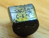
Not finding any other transistors close in number to the S8050. The S8550 is PNP.

I'm near positive the original is Sx050.. so that only leads to the 8050 which didn't work.

Any way to test the chip? Would the black cover peel off? Is it likely just a plain old microchip under there?
 
To avoid these ads, REGISTER NOW!
OP
S

Snapped-off

Well-known member
Joined
Feb 22, 2012
Messages
4,812
Location
Indiana
Just doing some more testing I soldered a lead wire to the battery minus so I can clip the meter lead onto it for easier testing.

4 switches on the track, labeling for the sake of the post, these aren't their actual numbers.

From battery minus to the right pin of R5 (Y V Y) sw1 gives 0.68, sw2 gives 0.81, sw3 gives 0.68, and sw4 gives 1.5 VDC. As soon as you let go and the switch opens voltage returns to 0.58.
 

Max

ALLIANCE MEMBER
Joined
Jun 16, 2018
Messages
3,351
Location
Georgia
[lots deleted]

Thinking out loud (this is directed more to Max): What if the transistor is a Darlington?
Sorry FTW - I missed your question the first time.

For the folks that are following along, a darlington is a pair of transistor‘s “stacked” such that the collector of the first one drives the base of the second one. From the outside it looks very much like a single transistor and it can be packaged like a single transistor. The advantage is that the gain of the two transistors is multiplied so it can have a very high gain.

FTW, if I had some darlingtons around I would have sent one as I was concerned about that as well. (I almost sent some FETs as well but due to the resistance tests we are sure it’s a NPN.). But I think it isn’t a darlington as the AC we measured from the COB to the base was about half a volt. A darlington would need 1 to 1.5 V to get both of the bases conducting well.
 

Max

ALLIANCE MEMBER
Joined
Jun 16, 2018
Messages
3,351
Location
Georgia
One problem with reverse engineering transistors is that many times the part numbers on the part were silk screened by the mfg. to meet their customer's part number. As an example, HP had their own internal part numbers for all of the parts they put on a board, and they were marked that way. So you had to look up the HP part number, and then it might specify a standard part that fit that part number, or it might be a sorted version of the part number, or it might be a unique part. So I don't want to discourage you, but that part number may only make sense to the folks that made the toy.
 
OP
S

Snapped-off

Well-known member
Joined
Feb 22, 2012
Messages
4,812
Location
Indiana
One problem with reverse engineering transistors is that many times the part numbers on the part were silk screened by the mfg. to meet their customer's part number. As an example, HP had their own internal part numbers for all of the parts they put on a board, and they were marked that way. So you had to look up the HP part number, and then it might specify a standard part that fit that part number, or it might be a sorted version of the part number, or it might be a unique part. So I don't want to discourage you, but that part number may only make sense to the folks that made the toy.
Well that *****. I wonder if Fisher Price still has any drawings of their 20 year old toy.

On another note, I just watched a video about transistors and semi conductors and I've got an even better understanding of their workings now.

Is the only hope shotgunning transistors at it? I don't mind buying more.. just don't know what I need based off of their specs.
 

Max

ALLIANCE MEMBER
Joined
Jun 16, 2018
Messages
3,351
Location
Georgia
Sorry for my slow progress, but I've got other projects interfering. I've got a leak in the outside wall of my office, and I just opened it up today - lots of mold and rotted out OSB. This is all behind bricks so it'll be the pros for that one. Anyway...

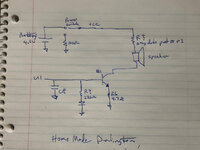
I made some progress on the schematic and it's below:
 

Attachments

  • schematic 1.jpg
    schematic 1.jpg
    298.9 KB · Views: 17

Max

ALLIANCE MEMBER
Joined
Jun 16, 2018
Messages
3,351
Location
Georgia
I may have mistakes, as it's really hard doing this from pictures. So a couple of observations:
- When we measured the ac voltage before that really doesn't tell us as much as we'd like. The issue is that we don't know if the output of U1 is some kind of PWM or AC signal, and the Fluke will have a limited frequency response. So the voltage may be significantly higher than the Fluke is telling us. If we had an oscilloscope we'd know exactly, but not many folks have one at home. So lots of words to say that the AC we measured may be higher than we measured, or it may be accurate.
- If the output is PWM then C8 is likely an integrator, and if it's AC then c8 is likely some kind of higher frequency roll off. Once again hard to say without a 'scope.
- Snapped-off, your post 83 had a resistor with two gray dots on its leads. Can you tell me the colors on it? It's not critical but it might help to know its value.
- The 220 ohm resistor and the diode on the base of Q1 are interesting, and I think it makes it more likely to FordTruckWench's thought that the transistor could be a darlington. When on, the base of the transistor is in the range of .5 to .8 volts. The same is true for the diode, so it seems either redundant or kind of a very lame clamp. On the other hand, if the transistor was a darlington then it could be a clamp.
 

Max

ALLIANCE MEMBER
Joined
Jun 16, 2018
Messages
3,351
Location
Georgia
So I think that the next step is to try a darlington. The good news is that we can make a cheap one using two transistors. I did send you two 2N3904's, so please try this hookup:

The letters by each transistor show that transistor's leads, and the letters in quotes are how you hook it up to the pcb.
 

Attachments

  • darlington1.jpg
    darlington1.jpg
    284.3 KB · Views: 17
OP
S

Snapped-off

Well-known member
Joined
Feb 22, 2012
Messages
4,812
Location
Indiana
So I think that the next step is to try a darlington. The good news is that we can make a cheap one using two transistors. I did send you two 2N3904's, so please try this hookup:

The letters by each transistor show that transistor's leads, and the letters in quotes are how you hook it up to the pcb.
So base 2 to emitter 1, emitter 2 to circuit, collector 1 & 2 together into the circuit.
 
  • Like
Reactions: Max
OP
S

Snapped-off

Well-known member
Joined
Feb 22, 2012
Messages
4,812
Location
Indiana
- Snapped-off, your post 83 had a resistor with two gray dots on its leads. Can you tell me the colors on it? It's not critical but it might help to know its value.
That's R4 and to the best of my eyes it's either Silver or grey R Go Go
 
  • Like
Reactions: Max

Max

ALLIANCE MEMBER
Joined
Jun 16, 2018
Messages
3,351
Location
Georgia
So base 2 to emitter 1, emitter 2 to circuit, collector 1 & 2 together into the circuit.
Yes. And base 1 to circuit base. I think that the gain on the 2n3904's was about 150 on each one, so total current gain will be over 20K.

And thanks for the resistor info - should be gray-red-gold which is 8.2 ohms - which seems like a reasonable value.
 

Max

ALLIANCE MEMBER
Joined
Jun 16, 2018
Messages
3,351
Location
Georgia
As a side note the power switch wiring is interesting. I may have made a mistake, but it looks like when the power is off there is a 100 ohm resistor from Vcc to ground. That could be to protect against ESD or maybe power off pops from the speaker. In either case it's better (ie., more expensive) design than I would expect on a toy.
 
OP
S

Snapped-off

Well-known member
Joined
Feb 22, 2012
Messages
4,812
Location
Indiana
Shot an email off to Mattels parts/service line but I'm expecting they won't offer any assistance.

They made a few different versions of this toy (non Christmas), so I suspect that's why there are some blank spots on the board for components.
 

Max

ALLIANCE MEMBER
Joined
Jun 16, 2018
Messages
3,351
Location
Georgia
Shot an email off to Mattels parts/service line but I'm expecting they won't offer any assistance.

They made a few different versions of this toy (non Christmas), so I suspect that's why there are some blank spots on the board for components.
Yeah, it's common to have one board in multiple products and you load the board differently depending on the product.
 
To avoid these ads, REGISTER NOW!
OP
S

Snapped-off

Well-known member
Joined
Feb 22, 2012
Messages
4,812
Location
Indiana
Ugh. OK. What were the DC voltages on the E, B, C again? (ref to battery minus) I think that C was ~4.5V and E was ~0V? And the AC voltage ref to battery minus?
DC
B- to E 0
To B 0
To C 4.5

AC
B- to E 0.15mV
To B 1.5mV
To C 0.3mV
 

Max

ALLIANCE MEMBER
Joined
Jun 16, 2018
Messages
3,351
Location
Georgia
You have to hit a switch or something to make it make noise, correct? Can you do that and measure BE AC? Right now the transistor is off and nothing is turning it on. And 4.5V on C means that the battery is ok and the switch is on...
 
OP
S

Snapped-off

Well-known member
Joined
Feb 22, 2012
Messages
4,812
Location
Indiana
AC
Transistor B To E is 0.28mV - 0.32mV. It bounces around a lot. If I press a switch it goes up instantly into the 0.32 range and when I let go it drops back down. But it's still all over the place.
 

Max

ALLIANCE MEMBER
Joined
Jun 16, 2018
Messages
3,351
Location
Georgia
All over the place is ok. .32V is low (won't turn on the transistor), but it could be more and the meter is reading low. I was worried that U1 was blown, but it doesn't look like it.

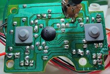
Are there other places on the board that you soldered or resoldered things? I am about out of ideas, except for a last visual check for shorts, bad solder joints, etc. So a good picture of the board with the camera parallel to the PCB would help for that. No hurry as I'll have to log off for the night shortly...
 
OP
S

Snapped-off

Well-known member
Joined
Feb 22, 2012
Messages
4,812
Location
Indiana
Haven't soldered anything else aside from a pigtail wire off the battery minus so I could clamp the meter to it. Saved from needing a 3rd hand to work the meter and close the switches.

I know it was mentioned prior to reflow the connections but I really can't imagine there's any problems there. It worked... until the base lead broke.
 

FordTruckWench

Well-known member
Joined
Jan 8, 2015
Messages
539
Location
California
From battery minus to the right pin of R5 (Y V Y) sw1 gives 0.68, sw2 gives 0.81, sw3 gives 0.68, and sw4 gives 1.5 VDC. As soon as you let go and the switch opens voltage returns to 0.58.

Very unexpected. But as I said, I think this is a red herring.

So I don't want to discourage you, but that part number may only make sense to the folks that made the toy.

More about transistor numbers: There are tens/hundreds/thousands of different part numbers that may all be the exact same piece of silicon. The difference is in which specs are guaranteed. If the transistor didn't meet one spec, maybe it meets another. A sensitive circuit may demand the highly spec'ed part, while a toy that needs a transistor to turn on an LED gets the "floor sweepings".

An analogy using lag bolts: PN1 has a 5/16 shank. PN2 has an 8mm shank. PN3 is 2 inches long. PN4 has a zinc finish. PN5 is 2 inches long and has a zinc finish. In reality, these are all the same bolt.

Knowing the above, we don't really need to find the exact part number. We know it is an NPN in a TO-92 package. Almost any transistor that meets this minimal spec should work.

I made some progress on the schematic and it's below:

My eyeballing the pictures came up with the same - except that the power off resistor is 10 ohms (black, i.e. zero multiplier).

...

An idea: What if C8 developed an internal short while the OP removed the transistor? My suggestion is to unsolder one leg of C8 - it should be possible to **** away enough solder such that the lead no longer contacts the trace.
 
OP
S

Snapped-off

Well-known member
Joined
Feb 22, 2012
Messages
4,812
Location
Indiana
More about transistor numbers: There are tens/hundreds/thousands of different part numbers that may all be the exact same piece of silicon. The difference is in which specs are guaranteed. If the transistor didn't meet one spec, maybe it meets another. A sensitive circuit may demand the highly spec'ed part, while a toy that needs a transistor to turn on an LED gets the "floor sweepings".
Makes sense. That's what I was wondering if something should be happening with one of these transistors, even if it's not the exact design spec. Should I start checking the other components?
 

Max

ALLIANCE MEMBER
Joined
Jun 16, 2018
Messages
3,351
Location
Georgia
Makes sense. That's what I was wondering if something should be happening with one of these transistors, even if it's not the exact design spec. Should I start checking the other components?
The application for this transistor is very vanilla - low frequency, low power, and low voltage. Many, many different transistors should work.

It’s possible that another component is bad. But in my opinion it’s not likely. I would go over things that might have been damaged by handling - broken wires, wires or components that got bent and might be shorting now, etc.
 

Max

ALLIANCE MEMBER
Joined
Jun 16, 2018
Messages
3,351
Location
Georgia
Sorry - another question. When you measured AC at the base, you said .28-.32 mV. When ypu pressed a switch you said .32. Was that V or mV?
 

Max

ALLIANCE MEMBER
Joined
Jun 16, 2018
Messages
3,351
Location
Georgia
I missed that the first time. That voltage is much too low. Can you see under the socket? It seems like the base is shorted to the emitter…
 
OP
S

Snapped-off

Well-known member
Joined
Feb 22, 2012
Messages
4,812
Location
Indiana
I missed that the first time. That voltage is much too low. Can you see under the socket? It seems like the base is shorted to the emitter…
I'll check at home but I'm not sure where it'd be shorted. Unless it's elsewhere on the circuit.
 
OP
S

Snapped-off

Well-known member
Joined
Feb 22, 2012
Messages
4,812
Location
Indiana
Didn't get to play with it today. I should get to tomorrow. I'll comb the board for shorts. I'll probably remove a couple of the components near the transistor and check those as well.

Current pics
20220109_194550.jpg
20220109_194652.jpg
 

FordTruckWench

Well-known member
Joined
Jan 8, 2015
Messages
539
Location
California
I missed that the first time. That voltage is much too low. Can you see under the socket? It seems like the base is shorted to the emitter…

That's why I mentioned C8. It doesn't look damaged. However, what if whatever mechanical impact broke the transistor also hit the capacitor? It may be internally shorted.
 
OP
S

Snapped-off

Well-known member
Joined
Feb 22, 2012
Messages
4,812
Location
Indiana
That's why I mentioned C8. It doesn't look damaged. However, what if whatever mechanical impact broke the transistor also hit the capacitor? It may be internally shorted.
I think me wiggling the transistor is what broke the lead. Wiggling got it working, and I likely applied too much wiggle.

I'm heading home so I'll check C8 out then.
 

dogdog

Well-known member
Joined
Nov 15, 2011
Messages
12,711
you might have to break out that oscilloscope there to verify if the signal to the base of that transistor is still good... you might have shorted the IC in one of the poking.
 
To avoid these ads, REGISTER NOW!
Top Bottom