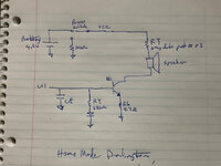
I may have mistakes, as it's really hard doing this from pictures. So a couple of observations:
- When we measured the ac voltage before that really doesn't tell us as much as we'd like. The issue is that we don't know if the output of U1 is some kind of PWM or AC signal, and the Fluke will have a limited frequency response. So the voltage may be significantly higher than the Fluke is telling us. If we had an oscilloscope we'd know exactly, but not many folks have one at home. So lots of words to say that the AC we measured may be higher than we measured, or it may be accurate.
- If the output is PWM then C8 is likely an integrator, and if it's AC then c8 is likely some kind of higher frequency roll off. Once again hard to say without a 'scope.
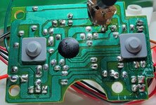
- Snapped-off, your post 83 had a resistor with two gray dots on its leads. Can you tell me the colors on it? It's not critical but it might help to know its value.
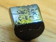
- The 220 ohm resistor and the diode on the base of Q1 are interesting, and I think it makes it more likely to FordTruckWench's thought that the transistor could be a darlington. When on, the base of the transistor is in the range of .5 to .8 volts. The same is true for the diode, so it seems either redundant or kind of a very lame clamp. On the other hand, if the transistor was a darlington then it could be a clamp.