Growlertdi
Well-known member
all of this is so above my head and out of my experience, but I am enjoying the detail you are going to in your posts. thanks! Looking forward to the end results!

Awesome work as usual Matt.
That is going to be an awesome build. Looks like you will have minimal up-travel, possibly only a couple to three inches. What kind of droop are you going to have? Around 8~ish or so?
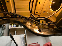
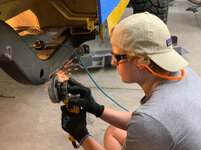
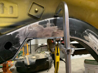
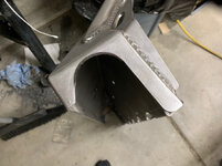
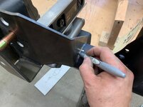
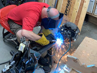
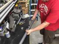
Looking good! I like the work with the sawsall. Probably a lot easier getting that through there than trying to get all the way around it with a cut off wheel


")


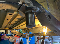
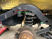
Thanks Mike! Honestly I’m not totally sure where it will land. When we got it, the Jeep had 2 1/2” OME coils in it and poly 1 1/4 budget boost pucks (front only). They had ~6” of bump stop (silly) in it which resulted in 3 1/2 inches of up travel. The down travel with the short arms sucked so I didn’t even bother measuring it.
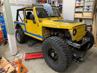
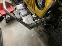
Total travel will be about 12” front and 14” rear. We want it low, rock rod low. With high-clearance 60’s, the TNT high-clearance belly pan, and 40’s It’ll do well on the trail and climb like a monster. It will feel very streetable and should stand out when I’m a crowd of other jeeps...of my vision comes to fruition.
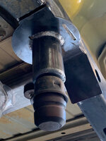
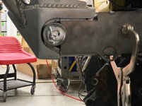
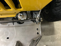
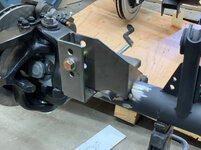
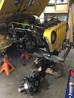
I’m concerned about how the Dana 60 will fit up under the engine. Rumor has it the yolk can get into the oil pan with lower lifts. Also the trac-bar into the frame and/or radiator can also be an issue when the wheel base has been stretched forward. If I have to add bump stop to solve any if these things, I might as well run the bigger springs.
I have 2 sets of coils. The PO’s setup 2 1/2 - 3 3/4”
(With the budget boost) or 4 1/2 all springs. Once the Jeep can sit on all 4’s again, we’ll swap them in/out and see where we are. The up travel will either be 3 1/2” or 5 1/2”.
The nice thing about a crawler is you really don't need a ton of uptravel, nothing like a desert racer or baja style build so you can still have a very capable rig even if you limit the uptravel and have a lot of droop. Also with those 40's bumping up against a ledge you won't have the possibility of getting under an undercut with a bit more droop than say a 35" or even a 37" tire. That was one of the reasons I limited my droop when I was running 35's was because left un-strapped they would get caught under ledges all too frequently and I'd have to back up and pick a different line. I noticed as soon as I strapped the axles, front in particular, that become less of an issue.
Great progress on the build so far Matt. I enjoy checking in and seeing the progress. Your son probably doesn't realize how fortunate he is to have you as a dad with your skillset and knowledge.


This might be my favorite thread on this forum. Nice work!!
Sent from my iPhone using Tapatalk
Excuse a dumb question from an Englishman who knows nothing about off-roading but what's the reason for the stretch?
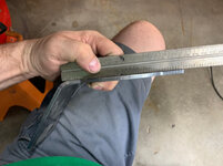
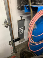
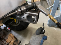
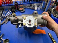
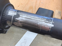
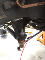
Just guessing here but it looks like clear silicone tape.
https://www.homedepot.com/p/Nashua-...sing-Silicone-Tape-in-Clear-1210364/203534911


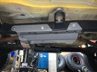

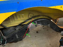
Will there be more skid plate under the sump(sorry,oil pan) or will you depend on the extra ground clearance to keep it safe?


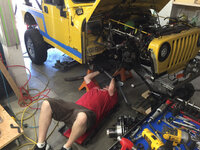

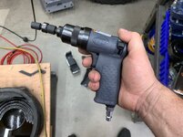
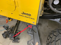
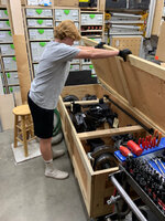
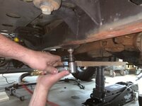
Can you tell us a bit about your handy floor jack, stock or customized?
Can you tell us a bit about your handy floor jack, stock or customized?
I don't want to speak for him, but it's a Pro Eagle. They come in various configurations for offroad use


Great progress. That Jeep is going to be a BEAST!
Impressed with how you are doing this. I wouldn't know where to begin other than to keep handing you tools!
Thanks for the details in this build!
I admire your consistent garage time to work on this. Something like this would take me years because I can't seem to get to the garage for more than an hour or two every few days. I love that you have daily updates.
I also am amazed at your ability to stop and take pictures. I have started many projects with the intention of doing a write up on it, but always wind up with a few pictures at the beginning of the project and one of the finished product. I can't bring myself to stop and take pictures.


Looks awesome! Maybe I missed it but what size wheels are those? I really dig that tire to wheel ratio. The whole giant wheel / low profile tire trend on trucks right now just looks bad.