Here is a manual online, with a wiring diagram. Does your control board have a number matching either the number in yours, or this one? Subtle differences in the information provided.
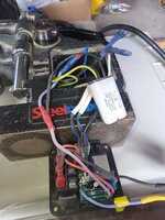
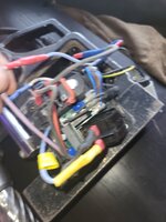
In the manual, it shows one leg of the power from the mag switch jumped on the board direct to the motor circuitry, which helps a little. Looks like the other leg is jumpered too, which could say that the motor doesn't really care if the magnet is working, only that the main power is on. (Q1 switch). So if you can find the labeled terminals (31 & 35) on the board, those two should connect to the inlet side of your motor switch. (Q2). The switch outlet should connect to your power filter (probably the grey MIFLEX thing), which should then connect to the motor. The MIFLEX may not be factory, as the wire colors don't match the drawing. The large number of **** splices could be a clue, look for your diagram colors on one side of the splices.
When things get goofy like this, I print out the diagram, and start marking things up in color to figure out what happened before you .
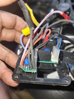
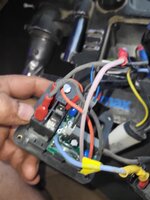
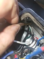
Your two button switch should have four numbers, one on each connection blade, 14, 24, and 13, 23, and then the A1, which shows up on this picture, attached to a blade. I think this is feedback for switched off.
Hi, I'm Ricky, industrial designer by trade, inventor by passion and necesity. I have a very small motorcycle design company, that thanks to BALDY and the guys at ADVrider is growing really fast. A few of my projects are bicycle racks for motorcycles and the most famous is my Pro-Taper...

patineto.smugmug.com
Also, S2 on the magnet connection is possibly an over temp switch, or a magnet energized switch, or maybe even touching down on a surface. Can't tell for certain without seeing it. Or checking it with a meter.
Enough for now, doing this on the phone is a major PITA. Take more pics, will try to look later.