To avoid these ads, REGISTER NOW!

Inside Doc's Shop...

OP
D

DocsMachine

Well-known member
Joined
Sep 16, 2006
Messages
1,874
But Doc you can stick a drill chuck on an MT arbor in the MT toolholder and just use that.

-Oh sure. There's a couple ways to do it. An MT block to hold an MT-arbor chuck, a boring bar holder to hold a straight-shank chuck, if the straight shank is small enough you can use a regular tool block... I have an ER-32 holder in a boring bar mount which I've used to hold drills, but as I said, swapping collets and drills is more time consuming than using a proper drill chuck

For this job, it was easy enough to just use the tailstock, but as I said, one of these days I plan to get the factory drill-chuck toolblock.

Doc.
 
To avoid these ads, REGISTER NOW!
OP
D

DocsMachine

Well-known member
Joined
Sep 16, 2006
Messages
1,874
Got a couple things I need to do with the oiling system in the Omniturn- one is to improve the pump and spray-manifold system, the other is to filter the oil to get rid of a heavy load of "fines", or tiny, almost dust-sized chips.

Not knowing where to start, I flipped a coin, used it to buy a Dew, and thus invigorated, decided to start on the pump and manifold.

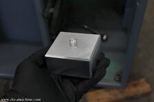
I had an idea for a way to add more nozzles, as well as keep them a little more out of the way of the tools. (I hope.) I dig through the scrap bins and found a chunk of 1" aluminum bar, and squared it up;

oilin001.jpg

oilin002.jpg

Measured a bit, and poked and countersunk a pair of holes 'bout there and there...

oilin003.jpg

An those will bolt it to a set of convenient mounting holes in the headstock 'bout like so:

oilin004.jpg

This won't work very well if I ever end up using a chuck, but I'm not sure that'll ever happen. If I need to hold something larger than 1", I have some "pot chucks", basically oversized collets, that can hold up to 2" or maybe a little more.

Anyway, I then drilled a big hole all the way through the long way on the block...

oilin005.jpg

And tapped it to 1/2" pipe at both ends.

oilin006.jpg

Then along the edge, I figured I had room for five ports, so I spaced, drilled and tapped those to 1/4" NPT.

oilin007.jpg

Finally, just for aesthetics and to reduce the sharp corners, I beveled the top edges slightly.

oilin008.jpg

A bit of light sanding to smooth things up a but, blow all the chips out, and she's basically done.

oilin009.jpg

And, test-fitted:

oilin010.jpg

The original idea was to simply extend a short hose from the existing port above the headstock, down to the new block, but after some pondering, I decided I'll reroute the hose under the headstock. I may put a 45-degree 'street ell' to aim the hose more directly to the back part of the chassis, but it may not be strictly necessary.

The front edge will have five valves, each with a short Loc-Line coming off of it- they'll aim at the part from the 'front', whereas the tools come in from the 'top' and 'bottom'. That should keep the nozzles out of the way of the tools, though I'll need to be sure they're not so close they start catching "birds nests".

If five ports proves to be too many, I can always remove the line and just shut the valve- or even remove the valve and plug the port entirely.

Next up... either the pump or... the other pump. I haven't decided yet. :D

Doc.
 
OP
D

DocsMachine

Well-known member
Joined
Sep 16, 2006
Messages
1,874
Strikin' oil, part 2:

Popped the back panel off the machine, and removed the rock-hard and well-stained vinyl tubing that originally connected the pump bulkhead fitting to the headpiece I'd made when first got this unit.

oilin011.jpg

That got replaced with a new chunk of vinyl tubing, this time routed around underneath.

oilin012.jpg

Turns out I didn't need the previously mentioned 45 degree elbow- I'd thought the tubing was going to need to go straight toward the back, under that gap seen to the right.

oilin013.jpg

But, it was able to tuck up to the left, and loop around nicely. I left the hose a little long, since there may be modifications in the future.

With the rest of the ports populated, and short sections of Loc-Line installed, I gave it a test:

oilin014.jpg

With the current pump, I couldn't use the larger outlet nozzles- as you can see with just the two lower ones, there's not a whole lot of pressure left. But, that's somewhat made up by the additional nozzles, which I can aim to match up with more tools, now.

A quick collet change, load the correct program, aim a few of the nozzles a bit (and remove one as not needed) and punch the go-button. Works great!

oilin015.jpg

I may have to do some more fiddling around with lengths and nozzles and whatnot, and I'm toyin' with the idea of maybe making the top two into "fixed" nozzles. As in, short sections of copper tubing, that always spray on the main body of the part- since the vast majority of my pieces are all about the same size and length.

And, looking at the runoff oil, you can see the rivers of glitter in it. I really need to get a filter arrangement of some sort going.

oilin016.jpg

That's next on the list...

Doc.
 
OP
D

DocsMachine

Well-known member
Joined
Sep 16, 2006
Messages
1,874
Speaking of rivers of glitter... :)

I'm running three machines in which I'm using cutting oil, rather than water-based coolant. That oil, after considerable use, is getting full of "fines", the 'glitter' shown above. As this oil is ****** expensive, I can't just toss it and swap it with fresh like one would in their car. None of the machines have an onboard filter system- few of any of the smaller machines do- so a common solution is a "Freddy" type sump vacuum.

It's a portable pump-and-tank unit that you can roll up to a machine, pump the sump dry(ish) which also filters the fluid as it's being sucked up, and the fines and gunk left in the sump can be scraped and wiped up. The pump is reversed and the fluid pumped back into the sump, now cleaner than it was before. (With the right filter, almost as clean as new.)

A commercial unit is not cheap, and are typically considerably larger than I need- my machines hold about ten gallons, most commercial units start at fifty.

So, since this is something I'll be needing for several machines, and possibly multiple times a year, I figured I'd build my own. :)

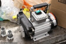
I started with an electric 'diesel fuel' pump off eBay...

sumper001.jpg

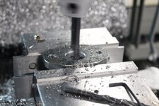
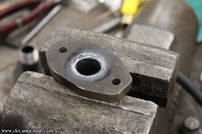
And made a couple of custom flanged inlet and outlet fittings. A couple chunks of 3/8" steel, bandsawed to shape and gently massaged in the belt grinder...

sumper005.jpg

Bored....

sumper006.jpg

Fitted with a chunk of 3/4 pipe cut to length and TIGged in place...

sumper009.jpg

And then faced back to flat and square in the lathe.

sumper011.jpg

A couple of custom-cut paper gaskets, some good high quality RTV, and a quick trip to Homey-Dee since I didn't have any 8mm bolts in the shop. :)

sumper013.jpg

That gave me a place to hang an eBay filter head, and two bidirectional ball valves from McMaster, each fitted with 3/4" hose *******.

sumper014.jpg

The pump doesn't reverse, so to be able to reverse the flow and pump back into the sump, we're using the plumbing equivalent of an H-bridge. :) And, better still, the oil is filtered in both directions. Yes, I know the filter is on the suction side rather than the pressure side, but I wanted to protect the pump impeller from the debris that'll be picked up.

To be continued! :)

Doc.
 
OP
D

DocsMachine

Well-known member
Joined
Sep 16, 2006
Messages
1,874
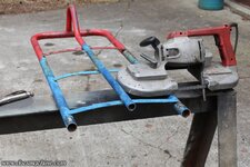
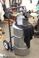
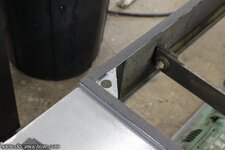
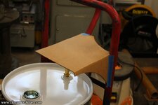
For the frame of this Sump Sucker, a lackey found me this lightly-used hand-truck carcass:

sumper015.jpg

I surgically removed the axle mounts for later use, and cut the whole frame down by about ten inches.

sumper022.jpg

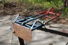
After a little grinding and fettling, I welded the platen back on...

sumper025.jpg

And after some adjustment, welded the axle mounts back on, to fit smaller cart type tires rather than the original pneumatics.

sumper028.jpg

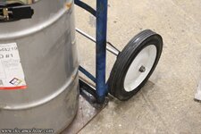
I then mocked up the tires and the 16-gallon steel drum I'll be using for a reservoir:

sumper030.jpg

And, a few minutes manhandling a chunk of 1" x 8" strap iron, got me a 'cradle' to help hold said tank in place.

sumper033.jpg

At the base, these two tabs clip to the bottom flange of the barrel, and secure it nicely:

sumper035.jpg

And, with it all welded in place, and a spare ratchet strap, there's the chassis mocked up.

sumper036.jpg

Again, more to come!

Doc.
 

larry4406

Well-known member
Joined
Jan 27, 2006
Messages
19,575
Location
Northern Virginia
For the frame of this Sump Sucker, a lackey found me this lightly-used hand-truck carcass:

sumper015.jpg

I surgically removed the axle mounts for later use, and cut the whole frame down by about ten inches.

sumper022.jpg

After a little grinding and fettling, I welded the platen back on...

sumper025.jpg

And after some adjustment, welded the axle mounts back on, to fit smaller cart type tires rather than the original pneumatics.

sumper028.jpg

I then mocked up the tires and the 16-gallon steel drum I'll be using for a reservoir:

sumper030.jpg

And, a few minutes manhandling a chunk of 1" x 8" strap iron, got me a 'cradle' to help hold said tank in place.

sumper033.jpg

At the base, these two tabs clip to the bottom flange of the barrel, and secure it nicely:

sumper035.jpg

And, with it all welded in place, and a spare ratchet strap, there's the chassis mocked up.

sumper036.jpg

Again, more to come!

Doc.
I like that bottom rim lock idea. Ain’t sliding off!
 
OP
D

DocsMachine

Well-known member
Joined
Sep 16, 2006
Messages
1,874
Backing up slightly, mocking up the pump assembly 'bout thar with a hunk of I-beam (everyone has a spare hunk of I-beam, right?) gave me a rough idea of where it needed to be mounted to the frame.

sumper031.jpg

A bit of generative CAD got me a workable shape for the pump mount/shelf thingie.

sumper032.jpg

That pattern I transferred over to some 10-ga steel plate, unfortunately including a last-minute change that turned out to have been a bit stupid. :)

sumper042.jpg

I then bent the first leg of that piece in the press brake...

sumper043.jpg

And then, to add lightness and panache, I knifed a hunk off with the plasma cutter.

sumper044.jpg

Why didn't I bandsaw it and then bend it? The short edge (at the left) would not have bent cleanly- it would have rolled in the press and given me a crooked bend. Don't ask me how I learned this, the hard way, many a moon ago. :)

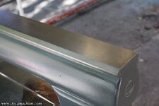
Anyway, that cut face went for a ride through the belt grinder, with a couple different grits, 'til it looked reasonably smooth.

sumper045.jpg

And finally, to cover up the stupid last-minute change I made, I bent the other 'leg', took one of the cut-off pieces, bent that in the press, cut it down, and carefully fitted it to the missing corner.

sumper046.jpg

That got TIGged into place as well...

sumper047.jpg

And ground smooth enough to hide my shame. :)

sumper048.jpg

Then, to complete the subterfuge, I also plazzed off a big chunk of that face...

sumper049.jpg

And ground it, too, smooth and to fit the hand-truck's odd dimensions.

sumper050.jpg

Still more to come!

Doc.
 
OP
D

DocsMachine

Well-known member
Joined
Sep 16, 2006
Messages
1,874
Somewhere about here, I picked up a hunk of 1/2" 304 stainless, and threaded it to 1/2"-13 on one end:

sumper037.jpg

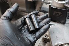
Then, since the axle bosses from the original truck were for a 5/8" shaft, I dug some scraps of black Delrin out of the scrap bin, and turned them into something closely resembling axle bushings... If you squint a bit.

sumper038.jpg

These got lightly pressed into place...

sumper039.jpg

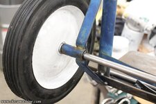
The axle slid through and marked....

sumper040.jpg

And of course cut to length and similarly threaded.

sumper041.jpg

I later installed a couple of Nylocks to make sure the nuts didn't go for a walk.

Still more!

Doc.
 
OP
D

DocsMachine

Well-known member
Joined
Sep 16, 2006
Messages
1,874
Getting back to the pump mount, with it tacked to the frame, I could eyeball a location and mark the bolt holes. I cut the tacks and took it to the drill press to punch the holes.

sumper051.jpg

And, with the mount now fully welded to the frame, another quick mock-up.

sumper052.jpg

Being reasonably satisfied- and having about nine hundred other things that I needed to be doing- I wire-brushed the frame a bit more, hung it up, hit it with some decent etch primer, and rattle-canned it with some "Dark Machine Grey".

sumper053.jpg

After that had a chance to cure for a bit, I bolted down the tank and pump, adding an old friction strap from my goodies bin, suitably cut to length, for the tank retention, and started running the hoses.

sumper056.jpg

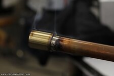
Which brings us to about the last bit: I needed a pickup tube to go into the tank. For this, I started with a hunk of 1" brass from the scrap bin, and cut and drilled it to a rough dimension.

sumper057.jpg

That got soldered to a couple feet of heavywall 1/2" brass tubing...

sumper058.jpg

And that, in turn, got... er, turned down to a finished dimension.

sumper059.jpg

In order to fit into another hose ******, and also get soldered into place.

sumper060.jpg

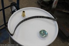
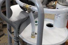
That, of course, gets screwed into the smaller bung of the barrel lid, and connected with another length of vinyl hose.

sumper061.jpg

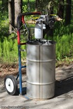
The rest of the hose gets hooked to the sump-suckin' end, the power cord zip-tied as a bit of strain relief, and there she is, ladies and gentlemen!

sumper063.jpg

The One and Only Super-Swampy Sick-Sump-Special Slime-Sucker Series Sixteen! :D

But we're not done yet!

Doc.
 
OP
D

DocsMachine

Well-known member
Joined
Sep 16, 2006
Messages
1,874
Now, does it work?

To start, I filled the filter with clean oil from a fresh can, to help "prime" the pump- it's a positive displacement vane pump, but still better to have some oil in there right away.

sumper064.jpg

And, you can see how much 'glitter' is in the oil- and this is after it's been left to settle for a week or more.

sumper065.jpg

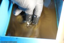
I couldn't easily hold the camera and operate the pump, having foolishly been born with just the two arms, but it sucked up the sump nicely, leaving a thin scum at the bottom that was probably half oil and three-quarters metal. :)

sumper066.jpg

I was able to pump the oil out of the sump, and then mostly back into the sump, before the flow fell off noticeably- the filter had rapidly clogged. I swapped it out with a fresh one, emptied the sump again, and this time fully scraping it out and wiping it down.

sumper067.jpg

But, as you can see, even after filtering it twice- through two filters- there's still a lot of fines in there.

sumper068.jpg

Here's the final result:

sumper069.jpg

It IS, believe it or not, cleaner than it was- and noticeably. It's easier to see in person- those white spots and some of the "swirl" you see are air bubbles, but there's clearly still a quantity of extremely fine debris in there.

The filters I used are listed as 10 micron, about 0.0004", or half a thousandth of an inch. Those particles are apparently smaller than that.

I can get some filters that should fit this unit, listed as 3 micron- two thirds smaller. I may pick up a couple of those and give them a try. I can see a cleaning cycle eating two filters each time, a 10 micron and a 3 micron, but that's over $500 in cutting oil in there, and $50 in filters to get another couple years of use out of it is a small price to pay. (This oil has been in the machine since late '21, so it took some two and a half years to get this bad.)

BUT... it also shows me I'm going to need to eventually invest in a proper high-flow filter system mounted to the machine itself. So that the oil is constantly filtered while it's in use. Such things are readily and commonly available, but not exactly cheap. A small setup I figure is going to run me over a thousand bucks, and involve a new pump in the turning center itself.

Long story short, this machine works, and pretty well. It's not perfect- I admit I was hoping for better results- but it DID clean the oil noticeably, and made it easy to clean the sump out, so it was definitely worth the time.

Doc.
 

SilverJimmy

Well-known member
Joined
Apr 14, 2012
Messages
1,682
Location
Prescott/Flagstaff, AZ
Back in my youth I worked as a Plant Repairman at a coal fired power plant. Spent many a graveyard shift doing what we called “the dishes” cleaning the lube oil delaval centrifuges.
They were high speed centrifugal cleaners, if I remember correctly they spun around 10,000 rpm, and any impurities were slung right out of the oil. Each unit had two of them cleaning the main turbine lube oil, and we had to clean them every night. One of these would clean your oil, you might find one somewhere as surplus. The ones I used to clean ended up at the bottom of a huge pile of scrap when that power plant was demolished.
 
OP
D

DocsMachine

Well-known member
Joined
Sep 16, 2006
Messages
1,874
A lot of people have suggested centrifugal filters, and on the surface, they sound ideal for something like this. My issues are both cost (a decent brand-name unit can be $500 or more) and I'm not sure how I can properly apply them in something like this.

For example, this kind of vane pump- a Jabsco-style rubber impeller- I don't think "deadheads" well. That is, if the flow of the pump is substantially more than the throughput of the filter, will I damage the pump? Overheat the cheap Chinese motor?

And I have to have a positive-displacement kind of pump- a centripetal wouldn't self-prime, making it a poor choice for this kind of machine.

I'm wide open to info on centripetal filters, I just don't know enough about them right now to justify having blown $500 or more for this setup.

That said, the plan at the moment is to install a "bag" type filter on the machine itself. That won't be cheap either, and will require a new pump assembly- which will in turn require heavily modifying the sump tub, but is the "right" way to go, here. Replacement bags can be had down to a few micron, and only cost $10-$12 each.

I figure at the rate I'm using this machine, one bag will last me the better part of a year.

what about a magnet on the filter or somewhere?

-Up until just the last couple of months, I never cut steel on this thing. It's been 90% aluminum, a little 303 stainless, and the rest some brass.

I'm doing some steel right now, but after this is done in the next few days, everything else I have lined up after that is back to those three.

Doc.
 

dutchgray

Well-known member
Joined
Sep 28, 2014
Messages
6,469
Location
Dorset. England.
Back in my youth I worked as a Plant Repairman at a coal fired power plant. Spent many a graveyard shift doing what we called “the dishes” cleaning the lube oil delaval centrifuges.
They were high speed centrifugal cleaners, if I remember correctly they spun around 10,000 rpm, and any impurities were slung right out of the oil. Each unit had two of them cleaning the main turbine lube oil, and we had to clean them every night. One of these would clean your oil, you might find one somewhere as surplus. The ones I used to clean ended up at the bottom of a huge pile of scrap when that power plant was demolished.
I would be looking for a scrapped large honing machine, some of those had centrifugal filters.
 
OP
D

DocsMachine

Well-known member
Joined
Sep 16, 2006
Messages
1,874
I'm not sure that where Doc lives is exactly a hotbed of cheap scrapped industrial machine tools.

-You can say that again. :)

This is closer to a machine tool desert. I've bought fifty percent of the lathes I've seen for sale up here- and that's not really an exaggeration. :D

On the centrifugal, yeah, I'm learning more about those, but as I was building this thing, a commercial unit was ten times the cost of the screw-on filter head I used, and I wasn't sure if the centrifugal would work in this instance.

The current plan (as always, subject to change :) ) is to switch this 'Sucker over to a small "bag" filter, which has a higher flow rating than most centrifugals, and a cheaper per-element cost than this screw-on.

I'll probably also install one directly to the turning center, so the oil is constantly filtered while in use. Not cheap, but I plan to put a lot of miles on these machines, and it'll be worth it in the long run.

Doc.
 
OP
D

DocsMachine

Well-known member
Joined
Sep 16, 2006
Messages
1,874
When I was finishing up a run of parts last week, the "collet close" button on the OmniTurn stared feeling a little wonky. Seeming like it needed a little extra encouragement in order to operate.

Until, in the last dozen or so parts, it stopped working altogether.

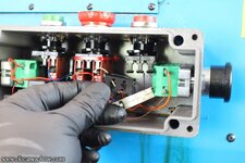
Fortunately, there's a duplicate control toggle up on the main control panel, so it was no big to finish off the run. Once I was done, and had attended a few other things, I cracked open the "operator control box" to see what was up. The issue, with the right-hand red button, was obvious:

buttonz1.jpg

What wasn't so obvious was the red zip-tie around the middle "E-Stop" button's switches, and the purpose of the black "blocks" under the left-hand green "collet open" button.

I have not dug into either of those, as they're still working, but I suspect they may both be suffering the same problem:

buttonz2.jpg

The little clips that hold the switch proper in place, which are surprisingly spindly, have cracked off. I suspect the middle one is cracked but holding, with the aid of the zip-tie, and the left one probably cracked, and somebody whipped up the expedient of jamming the two plastic blocks under it to hold it up.

The maker of the switches, Baco, doesn't seem to carry that style anymore, though I found two switches and the clips on eBay. No good, though, since the clip was cracked. I also can't slip in some of those arcade buttons, without modification- the two side buttons (which when pressed simultaneously, start the cycle) are in the way of the thicker arcade body, and the hole in the case is 22mm, and the arcades are 1" (25mm.)

The manufacturer of the machine sells all three, and for a not-absurd price, so I'll probably get them all before too long. But, I also need to order more tooling from them as well, and I figure I ought to get it all at once and try to save a little shipping.

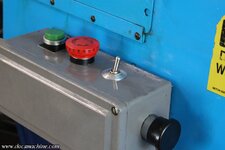
So in the meantime, I snuck over into a nearby secure installation, and salvaged a small momentary lever switch. What the heck, they probably won't need to "LAUNCH" anything for a while, anyway. :)

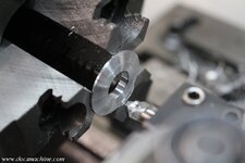
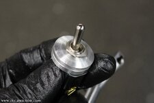
I then spent a few minutes in the lathe making myself a couple of spacer-washers, like so:

buttonz3.jpg

buttonz4.jpg

And voila! (which is a suburb just outside Voila-Voila, Washington.) A quick-and-dirty momentary switch repair, getting the machine back up and running, 'til I can place a parts order.

buttonz5.jpg

The only worry is that the switch is not in the last bit 'sealed' against the cutting oil which inevitably drips off my gloves as I'm working the machine. As such, it may well have a short life- but then, it just has to work for a week or two 'til fresh parts come in, so that should be enough.

Doc.
 
OP
D

DocsMachine

Well-known member
Joined
Sep 16, 2006
Messages
1,874
Ladies and gentlemen, I know it's not exactly a secret around here, but I... am an idiot. :)

I have no money, no time, and no space in the shop... and I just bought my ninth lathe.

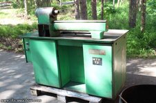
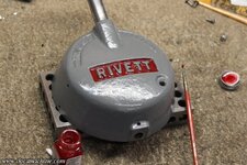
rivett001.jpg

Why? Because it was cheap enough I could actually kind of afford it, the seller rather deviously offered to deliver it, and worse, I'd kind of been thinking of something like this, anyway.

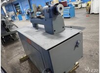
A couple years back, I picked up that little Hardinge 'speed' lathe- which has since proven so useful, I've wished I'd bought the full-size DV-59 version of it, so I could also mount a small turret. Yes, I have the big Warner & Swasey turret, but there's been times I've needed to drill or power-tap small parts, with like 1/16" drills. The W&S is overkill, and also kind of too slow, for something that tiny.

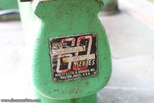
This one is a Rivett Series 60, which is nearly functionally identical to the Hardinge DV's; high spindle speed, takes 5C directly, uses a light turret, generally same size and weight, etc.

rivett002.jpg

I'll be honest and say I'd have rather had the Hardinge, as tooling for those is plentiful- in contrast, tooling of any sort for Rivetts in general is rather rare, and for a Series 60, even more so.

In this case, I have the turret, and I think I can adapt a Hardinge X/Y slide, and that's really about all I'll need.

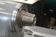
One interesting part of this unit, is the spindle nose:

rivett003.jpg

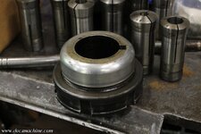
That threw me for a minute, but in the tooling that came with it, was this cap and ring:

rivett004.jpg

This lathe, therefore, can take the same L-00 chucks as my Sheldon, which offers interesting options. I have a soft-jaw 3-jaw set up for the Sheldon, and there's been a few times I've wished I could use a turret on that one...

One of the other more interesting bits in this machine, is the spindle drive:

rivett005.jpg

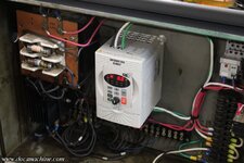
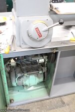
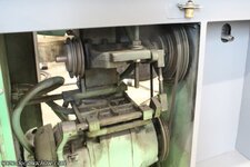
That's a motor-generator setup. One of those two motors you see is an AC 2HP 3-phase motor, and the other is a DC generator. DC voltage from that drives the DC spindle motor seen in the background. It's similar to, but not as sophisticated as, that of the older 10EEs. Today we'd use something like a big servo motor and electronic control, or a simple 3-phase with a good VFD, but this was how they did things in the 50s. (The estimated vintage of this machine.)

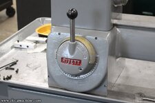
The system is controlled by this big lever at the base of the headstock. You need to swap the physical pulleys to get into different ranges, but in that range, the lever switches speeds.

rivett006.jpg

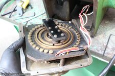
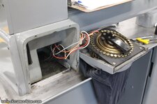
Inside that switch, is what is essentially, I think, a big rheostat:

rivett007.jpg

I don't even pretend to know exactly how it works- but would be interested to hear an explanation. I'm hoping I can clean this knob and faceplate assembly, without damaging the electrics.

rivett008.jpg

Oh, the other part of my idiocy? I bought the machine almost sight-unseen, and didn't even bother trying it before starting to pull it apart. :)

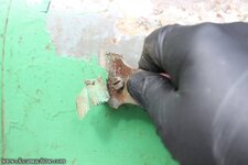
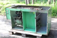
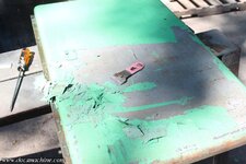
Pull it apart? Of course I did. I hated the color, and even if I didn't, the paint was in godawful shape anyway. A quick check with a razor blade showed the stuff practically falls off. I could blow sections off with compressed air.

rivett009.jpg

Thankfully, aside from the drive, it's a fairly simple machine, and didn't take long to fall apart.

rivett010.jpg

rivett011.jpg

rivett012.jpg

I'm not going to disassemble the electrics or the drive, so I'll have to hand-scrub and degrease the chassis, but at least here, the green seems to be holding well. Hopefully I'll just need to sand it, maybe fill a couple chips with spot-putty, then etch-prime and paint.

Wish I had the time to make a video out of this...

Doc.
 

dutchgray

Well-known member
Joined
Sep 28, 2014
Messages
6,469
Location
Dorset. England.
Your 9th lathe, looks decent enough for a second op machine.

Those 22mm modular panel switches are standard industrial parts, I would have bought some of the same type and not worried at all about trying to get the same manufacturer.
 
To avoid these ads, REGISTER NOW!
OP
D

DocsMachine

Well-known member
Joined
Sep 16, 2006
Messages
1,874
Those 22mm modular panel switches are standard industrial parts, I would have bought some of the same type and not worried at all about trying to get the same manufacturer.

-Oh sure, I can get panel buttons from a number of sources. But in this case, note how the buttons coming in from the sides, kind of "overlap" where the two top buttons go. On the left side, you can see they actually had to snap off a couple of the switch clips to make it fit.

Since I generally can't be sure a random button- unless it comes with detailed drawings and measurements- will actually fit, my safest bet is to stick with the stock stuff. (Which costs about the same as other makes, anyway.)

Doc.
 
OP
D

DocsMachine

Well-known member
Joined
Sep 16, 2006
Messages
1,874
Had very little time to spare, today, but still had to do something on it. I'm not kidding when I say our summers are way too damned short. Summer itself is really just three months long -June, July and August- and of those, maybe a third of them are warm, dry days where it's actually pleasant to do something outdoors. I have a few days- 'til late this weekend, according to the forecasts- 'til it rains, so I'm hoping I can at least get the base cabinet cleaned, painted and into the shop.

Anything after that is easy enough to bring inside if it's gonna sprinkle.

Anyway, all I did today was pop the drip tray off the top of the cabinet, and scrub down what I could, that didn't risk getting water on the electricals.

rivett013.jpg

The right-hand storage cabinet cleaned up nicely, though I don't plan to actually paint in there. The 'footwell' is pretty well scrubbed out- some previous owner painted over some swarf and mud in the corners - and the right end and part of the back is pretty clean.

When I next have time, I hope to sand those faces lightly and at least prime them.

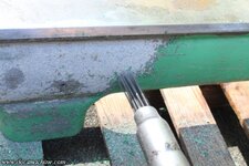
While I was doing that, periodically hosing it with Purple ZEP, letting it soak, scrubbing, then hosing carefully, I'd take turns hitting the bed casting with a needle scaler.

rivett014.jpg

I started out trying to use paint stripper, but the modern non-methylated stuff doesn't seem to work very well. I should have just started with the needler.

The only drawback of that is it strips the filler too- although to be honest, the filler can soak up the stripper, and 'bubble' the paint later, if it's not well-rinsed. Six of one, and all that...

If it's too rough after I sand it, I can give it a skim coat of filler like I did on the little Hardinge.

Anyway, after switching back and forth a bit, I had the casting pretty well cleaned off- the white is just traces of the filler.

rivett015.jpg

With luck, maybe I can have these two pieces painted (okay, three, with the drip tray) and reassembled by the weekend.

Doc.
 
OP
D

DocsMachine

Well-known member
Joined
Sep 16, 2006
Messages
1,874
Here's an example of one of those paper tags inside the cabinets. This is the worse of the two:

rivett016.jpg

I have the full-res, of course, and at some point I'll try to clean it up digitally. On this one, one corner was loose, but I tore it slightly trying to go any further. I may try to dribble a little alcohol on it, either to loosen the adhesive, or to see if the staining can wash out a little.

It basically explains how some rubber isolating feet need to be installed after first delivery. On the right, it suggests the generator brushes can be inspected by removing the vented end cover. I'll probably do that before too long, just to see what kind of shape the brushes are in. (It's a Blador power unit, I wonder if they'd still have brushes...)

Also, not that we really needed it, here's proof of the repaint:

rivett017.jpg

The brighter green on the left is the repaint, the duller green is the original factory color. Whoever did the repaint often applied it over dried oil and coolant stains, and it basically fell right off.

Normally I'd strip something like this down to bare metal- or close to it, anyway. But time is short, and I also don't want to have to try and remove all the drive motors and electrics.

As it is, I spent a good couple of hours scrubbing, degreasing and rinsing. This will not be one of my best-ever paintjobs, but the more time spent now, the longer it'll last.

rivett018.jpg

Finally, scrubbed, scraped, rinsed, wiped, degreased and rinsed again.

rivett019.jpg

And, while I was wrapping the motors against drips and overspray, I noticed the first mechanical issue:

rivett020.jpg

It's hard to tell in that pic, but that black bar in the center is the key to the shaft for that pulley. It's walked out, and stopped only by hitting the cabinet wall, where it's scored a small circle.

Obviously, before I light this thing up for the first time, we'll need to address that.

Anyway, with a few bits of masking paper here and there, I then spent a good long while sanding anything I could reach:

rivett021.jpg

After blowing off all the dust, a can and a half of spray self-etching primer...

rivett022.jpg

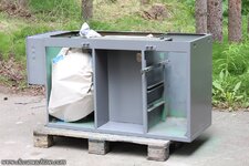
And finally, the first coat of "Lathe Grey" enamel.

rivett023.jpg

As I said, this will not by any means be the best paintjob I've ever done, but personally? It already looks roughly a million percent better. :)

(I really hated that green.)

Doc.
 
OP
D

DocsMachine

Well-known member
Joined
Sep 16, 2006
Messages
1,874
I know it doesn't look that much different from the last photo, but here it is with the second coat:

rivett024.jpg

Later this weekend, when it's decently dry (it's only in the mid-50s) I'll hire some help and get it rolled into the shop. This was the big piece- the rest of it is small enough I can take care of it at my leisure, inside or out, rain or shine.

Question for you lot: I'm considering removing the VFD (a recent addition by the previous owner) and running it on straight 3Ph out of the 10HP rotary converter. I'm told the drive can "backfeed" on fast braking or reversing, and trip out the VFD. The rotary would avoid that.

To do that, I'd need to refit a disconnect at the lathe end, so I'm looking for a switch something like this:

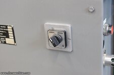
switch.jpg

I can find conventional 3-ph switches just about anywhere, I'm just wondering if I can dig up an "old style" that looks something like this one. Just for aesthetics, of course- if I can't find one, I'll go with a modern Allen-Bradley from McMaster or something.

Doc.
 
OP
D

DocsMachine

Well-known member
Joined
Sep 16, 2006
Messages
1,874
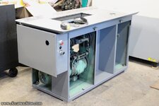
Got the cabinet moved into its new home, pretty much the very last spot a machine of any real size can go in the shop, unless I start getting rid of others- which is of course unthinkable. :)

rivett025.jpg

With that safely out of the way, I finished scaling the paint off the bed casting, and sanded it reasonably smooth.

rivett026.jpg

One thing to take care of before painting, was to fix the one broken-off rivet that held the ID tag on.

rivett027.jpg

Luckily, unlike some other machines I've dealt with, which have used hardened-steel rivets, this one used simple brass brads. I was able to centerpunch the brass, and the drill followed it, over the slightly harder iron.

Then, it was a simple matter to tap them for 4-40 screws:

rivett028.jpg

By the way- that center cap is a plastic plug. The bed casting is hollow, and I'm sure that was a sort of fixturing hole, to align the casting for machining. The plug keeps coolant or cutting oil from oozing behind the tag and getting into the casting.

After that, I masked it up, and hit it with two coats of etch primer.

rivett029.jpg

While that was drying, I hosed the chip tray down with more Purple ZEP, and gave it a good scrubbing.

rivett030.jpg

And rinsed. I know it doesn't look all that much better, but at least now it's not as greasy. :)

rivett031.jpg

Flipped over on a couple of trash barrels, I scraped, scrubbed and degreased the bottom, too.

rivett032.jpg

When I have more time, I'll give it a perfunctory sanding, at least out around the edge, before I prime and paint.

It's worth noting that the original color for this machine is, in fact, grey. The green must have been sprayed on by some early owner, maybe to get it to match the other machines. But the green on the underside- the duller "original" green- was clearly sprayed over some swarf and coolant stains, and damn near fell off, again, often just with the pressure washer.

Anyway, with the primer pretty well cured on the bed casting, I have that its first coat of the grey enamel.

rivett033.jpg

I'm risking a lowish chance of rain in the morning, but I can always hang a tarp or something if it sprinkles.

Busy week coming up, so progress will be slower from here on out. With luck, first chips by next weekend!

Doc.
 

Chrisb62

Well-known member
Joined
Jul 30, 2019
Messages
1,093
Location
southwest fl
Question for you lot: I'm considering removing the VFD (a recent addition by the previous owner) and running it on straight 3Ph out of the 10HP rotary converter. I'm told the drive can "backfeed" on fast braking or reversing, and trip out the VFD. The rotary would avoid that.
It will indeed trip the VFD, with rapid starts and stops, your rotary converter is the better idea.
If the last owner put lots of small delays on ramp up and ramp downs on spindle it may not trip the VFD. Not knowing exactly how you may end up using the lathe and having the rotary available , I would go with rotary. Just my two cents…..
 
OP
D

DocsMachine

Well-known member
Joined
Sep 16, 2006
Messages
1,874
Thankfully, the paint had had a chance to at least partly cure before it rained, and I was able to gently wipe it dry. Then, I did what I should have done last night, and got out the pop-up canopy. Some of these pieces will have to stay outside for a few more days, and it looks like the weather is going to be typically wonky this coming week.

rivett035.jpg

That is, unfortunately, the big drawback to filling the shop with machines- I neither have the room to work on something this big anymore, and I can't do any sanding or spray-painting inside- anything that produces dust or grit.

But, I use these machines to make my living, so that's the way it goes. :)

Once the bed was a little more dry- that is, both in the "moisture" sense as well as the "paint cured" sense :) - I applied a second coat. I hadn't intended to go much further today, I have a stack of things I need to get done this week, but the rain thing cheesed me enough I want to get the bed and the drip tray done and indoors as soon as I can. The rest of the stuff is small and can be moved and handled easily, inside or out.

So I went ahead and scraped the drip tray- and while I was doing that, I hit some of the smaller parts with some paint stripper. I alternated between these two, but I'll show 'em here "in order" to make it more clear.

The stripper I'm using, since I can no longer get the methylated stuff, doesn't work very well, but I came up with a trick to get the best results I can out of it. I put 'em in a pan- that the stripper won't eat- and soak the parts well:

rivett036.jpg

Then, cover it to keep the fumes in. That seems to both help the reaction, and reduces the stink in the shop.

rivett037.jpg

After a while, the paint has bubbled enough it scrapes off with some ease, and then I rinsed them off in a bucket of warm water.

rivett038.jpg

They still need to be sanded and primed, but this was just an effort to try and get as much done with my time as I can.

rivett039.jpg

Meanwhile (and alongside, also simultaneously) I hit the drip tray with a razor scraper, and got as much of the loose stuff off as possible.

rivett040.jpg

After that, I degreased it again, then hit everything with the DA sander. I didn't go too overboard trying to blend all the edges and whatnot- this isn't a show car. :)

rivett041.jpg

Then I flipped it over and did the top half, including hitting the bare-steel parts of the tray with the DA, to buzz off the surface rust, take down some of the nicks, and give it a generally more uniform finish. This is the side everyone sees, so I want to make it nice. :)

rivett042.jpg

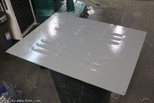
After that, it was simple: Get it set up under the canopy, hit the relevant bits with the self-etch primer...

rivett043.jpg

And once that's dry, roll on the first coat of enamel.

rivett044.jpg

Once I have a second coat, and that's dry, I'll install it, and paint just the lip, in place on the cabinet.

Oh, and I pulled the not-at-all-waterproof masking tape off the bed...

rivett045.jpg

[sigh] Fortunately, it seems to come off fairly easily with some Scotchbrite, and doesn't leave too much staining. Still pisses me off, though.

Doc.
 
OP
D

DocsMachine

Well-known member
Joined
Sep 16, 2006
Messages
1,874
Got quite a bit done today- both in the shop and on the new machine. :)

Before I started reassembling things to the cabinet, it needed to be properly leveled. This section of the shop used to have a drain, which has long since been filled in, but the floor still 'slopes' towards it. This necessitated a little bit of customizing...

First, though, the lathe has these adjustable screw 'feet'.

rivett046.jpg

Common to many machines, the Springfield has ones much like it. (Eight of them much like it. :) ) The only problem being they only had about 3/8" of usable adjustment- they're only intended for minor unevenness, and fine-tuning the level of the machine. The floor slopes just a bit more than that... :)

So, for the first two corners, the ones that need the least "rise", I bandsawed and milled-square two 3" chunks of 1/2" 'luanmum.

rivett047.jpg

These I drilled and bored in the center to 1/2", simply using an endmill.

rivett048.jpg

And, just for a little style, I chamfered the top edges a bit.

rivett049.jpg

I then made some 1/2" long barrel pegs out of 1/2" round stock...

rivett050.jpg

And corked those into the plates with a dab of red LocTite.

rivett051.jpg

The plate spreads the load a little, and the 'peg fits into the bore of the adjuster (hollow because the machine was bolted through them to a shipping pallet when it was first sold) so the machine can't walk off the plate, or the plate slide out from under the foot.

rivett052.jpg

The third corner- rear right- needed a 1" thick plate, and the front-right corner, needed one a full inch and a half tall:

rivett053.jpg

That gets us pretty close to level-and you can see how little adjustment is left on the bolt.

rivett054.jpg

Et Voilá!

rivett055.jpg

rivett056.jpg

Next up, before the chip tray can go on, I needed to clean up the spring-loaded door latch detents.

rivett057.jpg

And get those installed.

rivett058.jpg

Now, when I took this thing apart, there were strips of a cork-gasket type material around the top edge of the cabinet, that the drip pan rested on. It was oil-soaked and disintegrating- this machine is around seventy years old- so I scraped it off and tossed it. For a replacement, I had a near-new roll of Homey-Dee tool-drawer liner, and sliced off a few strips with a razor knife...

rivett059.jpg

Which I then glued to the top rail with a few dabs of black RTV. It's not a "seal", it's really just an anti-vibration cushion.

rivett060.jpg

Then, while I was waiting for help to manhandle the drip tray back into place, I pushed that loose key back in, shifted the pulley over on the shaft a tad to better line it up with the motor pulley, and tightened the setscrew back down.

rivett061.jpg

I'll keep an eye on it and see if it works loose or goes for a walk again.

And, I got out some fresh Scotchbrite and some WD-40, and scrubbed the rust off the bedway as best I could.

rivett062.jpg

It's better than it was, but there's still more faintly-visible staining than when I got it. Kind of mildly annoying- concrete evidence of ones' laziness always is- but of course doesn't affect accuracy or performance.

Finally, help arrived and we got the drip tray worried back into place. (It's tricky to get the sump and it's drain 'rotated' into place when there's only just enough room for it.)

rivett063.jpg

Next up, several days of... more cleaning, sanding and painting! Yaaaay! (And there was much rejoicing.)

Doc.
 
OP
D

DocsMachine

Well-known member
Joined
Sep 16, 2006
Messages
1,874
Gettin' down to the last of the big bits- and good thing, too, as there's supposed to be nasty wind and rain in the next couple of days.

Inside one of the doors is another paper info tag, listing the speed ranges of the belts. It's in better shape than the other- being actually readable- but I still can't remove it. Thinking I was going to hose the outside of the door with the Purple ZEP and pressure-wash it, I taped it over with a plastic grocery sack.

rivett064.jpg

However, on a whim, I tried a simple razor blade scraper- and again, the green practically fell off.

rivett065.jpg

It took about an hour per door, and six or seven blades each, but I was able to get it down to the original grey, the original primer, or even bare metal with little effort.

rivett066.jpg

After that, a few moments with the DA got it buzzed down to baby-**** smooth- if your baby happens to be armor-plated, anyway. :)

rivett067.jpg

Then just primed...

rivett068.jpg

and painted!

rivett069.jpg

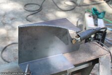
The back panel I wasn't so worried about, but I still needed to tweak it a bit. The corners had been dinged at some point, and needed straightening out.

rivett070.jpg

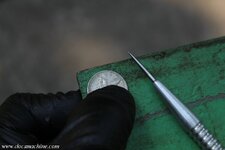
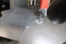
I also decided to cut a corner or two. :) Using a handy nickel- both appropriate, and being the lion's share of my remaining funds- I scribed a small radius at each corner of the panel.

rivett071.jpg

A pistol-grip air sander made short work of buzzing those down to shape...

rivett072.jpg

After which it, too, got scuffed (not even sanded) and painted.

rivett073.jpg

While I had the paint out, I also masked off the drip rail and gave it the first coat as well.

rivett074.jpg

I'll probably take the 4th more or less off- if you can call it that- but I'll still try and give each of those their second coat.

Happy 4th Of July!

Doc.
 
OP
D

DocsMachine

Well-known member
Joined
Sep 16, 2006
Messages
1,874
Today's weather was pretty blustery- but thankfully not raining, yet- so most of the cookouts I'd heard of had been postponed 'til the weekend. :)

So, on this day off from work, what do I do? Yep, go back into the shop and work some more. Jack is indeed a dull boy. :D

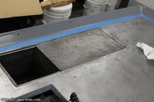
Trying to clean off the benches a little, I finished cleaning the sump screen and dropped that into place.

rivett075.jpg

And by 'finish cleaning', I mean I took a small hunk of wire and rodded out roughly a third of those itty-bitty holes, that were clogged with tiny chips or wads of what was basically mud.

With that arduous task out of the way, it was time to turn my attention to the headstock. I wanted to put a second coat on the doors and whatnot, so I figured I'd prep a few of the other bits and get a first coat on those, too.

rivett076.jpg

Interestingly enough, the front cover- which is just sort of a... guard plate, I guess, was missing half its screws for some reason.

rivett077.jpg

Same game as before- the loose stuff scraped off with a razor blade, the tough stuff ground out with a Scothbrite wheel, and the rest DA sanded.

rivett078.jpg

The headstock had a number of nicks and dings, and I didn't want to grind off ALL the filler, so I touched it up here and there with some spot putty.

rivett079.jpg

That too was sanded smooth, then the whole thing masked...

rivett080.jpg

Primed...

rivett081.jpg

And painted!

rivett082.jpg

While I had the paint out, I prepped and painted the two belt covers...

rivett083.jpg

And gave the chip-tray rails their second coat, after which I peeled off the masking tape.

rivett084.jpg

Before wrapping things up for the afternoon, I cleaned up the 'guard ring' a little, filing off some of the dents and dings, and then since the face was so beat up, I gave it a light skim cut to smooth it up.

rivett085.jpg

Friday's going to be busy for me, but hopefully Saturday I can shanghai some help again, and get the bed remounted to the cabinet. The doors and back panel should be properly dry, then, too- we won't be done this weekend, but it'll be close. :)

Doc.
 
OP
D

DocsMachine

Well-known member
Joined
Sep 16, 2006
Messages
1,874
Finally, the paint is dry on enough of these bits, we can start throwing this off-brand Erector set back together! :)

Easy stuff first- the back cover:

rivett086.jpg

(Besides, it'd been sitting on my trash can, and I've been needing that. :D )

The end vent cover over the motor-generator...

rivett087.jpg

And the little ID tag on the electrical box.

rivett088.jpg

I hired some help to get the bed casting back in place- it sits on three of these jacking points, each with this little semi-hemispherical washer, which fits into matching recess on the bottom of the casting. That allows for a small bit of misalignment, so the adjusters can be used to level the bed.
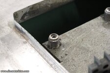
rivett089.jpg

After more fiddling than I care to relate, we got it socked down and the bolts placed.

rivett090.jpg

Note how high the right-hand end is, by the gap under the "foot". I wanted to lower that down a little, to reduce that gap, so that chips and gunk wouldn't keep collecting under there. But, that meant there was now a distinct downhill slope to it. And to fix that, I had to raise the low end another half an inch.

rivett091.jpg

I may revisit those feet eventually, but that should work for now.

I'd have thought that would throw off the level as measured at the chip tray, which was nominally level yesterday, but oddly enough, it was spot on, too. There were only a few places where this steel ball rolled in pretty much any direction.

rivett092.jpg

Next up, I decided to attend this nasty dent in the right-hand door nameplate.

rivett093.jpg

Some non-marring pliers and a small rawhide mallet, and I was able to gently massage it back to approaching straight-ish.

rivett094.jpg

It attaches to the door with four shiny new stainless buttonhead 4-40 screws, and it damn near looks new again.

rivett095.jpg

I then reinstalled the drawer slides and collet rack slide, before bolting the door back in place.

rivett096.jpg

'Couple interesting bits: Those aren't actually drawers. They're old heavy steel... I guess small crates, made by a still-extant company called Pollard Bros. They make heavy-gauge industrial stuff like benches, stools and worktables. Somebody mounted some angle-iron 'rails' inside the cabinet so that the boxes can slide in on them, like drawers.

I also don't know if this thing ever had a collet rack like that from the factory- the wood, at least, on this one is shopmade, and a bit wonky. Some of the holes are pretty tight on the collets. I may have to make a new one at some point.

Anyway, I had to tweak the adjustment on that latch/detent thing a little, but now the door closes firmly and snugly.

rivett097.jpg

The paint wasn't quite 100% dry on the headstock, but it was dry enough so that I could clean off the mating surfaces, spray a little LPS-3 in there and slide 'em together.
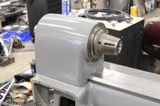
rivett098.jpg

I chased out the bolt holes- remember, some of them had been empty and open for a time- cleaned up the screws (and found some extras) and bolted the shiny clean guard ring back in place.

rivett099.jpg

I had earlier done a little bodywork to the sheetmetal protector cap, and primed and painted it, so that was easy to snap into place.

rivett100.jpg

And, out of curiosity, I pulled the X/Y slides off the little Hardinge, and tried it on for size.

rivett101.jpg

It doesn't "fit", at least not yet. The Hardinge uses a dovetail bed, while this Rivett has a more prismatic bed- more like a Weaver rail. I can mod the slides to fit, although that's one reason, as I said earlier, I kind of wish this had been a Hardinge- so I could more easily share tooling between them.

But, I'll have to make do. Once she's up and running, I'll start looking more closely into the tooling, and see what I have and can do there.

Anyway, that pretty much did it for the day:

rivett102.jpg

Over the weekend, I hope to get the "rheostat" switch cleaned and painted, and the rest of the electricals hooked up. Then we can actually try this thing! :D

Doc.
 
OP
D

DocsMachine

Well-known member
Joined
Sep 16, 2006
Messages
1,874
It's time to finally dive into the... for want of a better term, the "rheostat" control. Variable resistor, rotary switch, whatever you want to call it. :)

rivett103.jpg

Fortunately, the electrical part was easy to remove, with just three screws:

rivett104.jpg

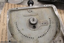
Leaving just the mechanical portion to play with. One interesting bit, is this semicircle of holes around the lever body. Heavily painted over, but clearly threaded- this little movable post can be shifted to any one of them, acting on a springloaded detent at the bottom of the casting. (The now-empty hole seen to the right.)

rivett105.jpg

That way, you can set the speed to a certain range, and just turn the lever 'til it hits that detent. It's not a hard stop, but it lets you know you're in the range, without having to look at the tag. You could have muptiple stops, too. Fast for drilling, slow for threading, medium for parting.

Speaking of tags, I pulled the corner screws, and it popped open- I suspect somebody had tried to remove it, and bent the ends outward.

rivett106.jpg

The corners were screws, but the center was still a rivet. I'm sure the corners were originally rivets, too, but whoever painted this thing last, tried to remove it. I couldn't grab it with the nippers, but I was able to carefully grind a screwdriver slot in it, and back it out. (These rivets usually have a 'helix' of grooves to help it grip the hole.)

rivett107.jpg

With both parts fully disassembled, I scrubbed off the grease and oil, and hit 'em with the paint stripper.

rivett108.jpg

Took a couple applications to get all the gunk off, including some detail work to scrape out the lettering.

rivett109.jpg

But they came out shiny clean!

rivett110.jpg

Still had a couple things to take care of, though- that ring of threaded holes had two broken-off screws:

rivett111.jpg

Fortunately, one was proud enough I could grab it with the nippers...

rivett112.jpg

And the other was loose enough I was able to tap it lightly with a ***** punch and unscrew it far enough to grab as well.

Of course, since most of the holes hadn't been used in years, and had been painted over maybe twice, I had to chase each one with a tap.

rivett113.jpg

All nine hundred and thirty-seven of them. :)

After that, laid out...

rivett114.jpg

And painted.

rivett115.jpg

After that, I cleaned up some more of the bolts, and stuck the back panels on, just to get them out of the way.

rivett116.jpg

I don't have the belts on yet- I want to try powering up the drive, first, and see what kind of noise, if any, just the drive alone might make. Turning the spindle by hand seems to make more noise than I'd expect, so we may have to swap some bearings before too long. This thing should be smooth and quiet when it runs.

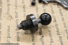
One other bit I cleaned up while I had the stripper out, was this... plunger thingy.

rivett117.jpg

Which just took a little cleanup, a dab of fresh oil, and... that was about it.

rivett118.jpg

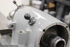
That fits in the headstock like so:

rivett119.jpg

Where it... doesn't do anything. :)

I believe it's supposed to be a positive spindle lock, probably for tightening or loosening chucks when using the L-00 spindle nose. This low-res image from a sales brochure from VintageMachinery seems to indicate that- there's a space on the inner edge of the pulley that presumably has grooves or holes for the pin to socket into.

rivett120.jpg

Except my pulley doesn't have that. The pin hits part of the pulley edge, and part of the belt itself- and the pulley shows no sign anywhere of a notch or hole for the pin.

I'm presuming the pulley has been replaced at some point- the locking ring shows signs of being both loosened and tightened with a hammer and punch, rather than a wrench. Why the pulley would be replaced I have no idea, but that's my best guess.

If I do have to crack the head open to swap the spindle bearings, I may play with the idea of making a new pulley, too, but the spindle lock is not a vital piece. Maybe I'll just label the knob "Self Destruct" and leave it at that. :)

Doc.
 
OP
D

DocsMachine

Well-known member
Joined
Sep 16, 2006
Messages
1,874
Very short on free time today, but I wanted to get at least one more nibble in on this elephant. :)

I couldn't do anything on the speed control pieces, apart from giving them their second coat. I also rummaged through my stashes and found a different knob for the handle:

rivett121.jpg

The big shop-made aluminum one was too big, and probably a bit heavy. This one seems a little more appropriate. :)

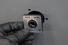
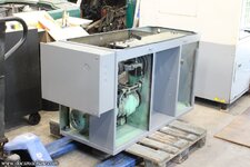
On the other end of the electricals, I wanted to add a shutoff/disconnect, so I didn't have to keep unplugging the thing. I was given an oilfield-surplus switch, of an appropriate rating and function- and no, I have no idea what it was supposed to "bypass".

rivett122.jpg

I may see if I can't flip that plate over, and print "SAFE" and "ARMED" or something. There's probably not enough room to pit "Safe" and "Decidedly less safe" on there... :)

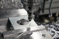
The biggest issue is that I had two holes it could be mounted in, and neither really worked. The switch body is too big to fit next to the other controls at the front of the panel, and the hole on the door was too large and the screw holes don't line up.

After some pondering, however, a solution arose. A simple application of a bandsaw...

rivett123.jpg

A big rotabroach...

rivett124.jpg

Some deftly-applied holes and a tap...

rivett125.jpg

And a countersink.

rivett126.jpg

That all bolted through the big hole like so...

rivett127.jpg

And done! Except for, y'know, the actual wiring, that is. :)

rivett128.jpg

In this case, "Bypass" is "on"- I suppose "normally, it's off" works as a menmonic. :D

The only other thing I did was I cleaned and straightened the tag that goes on the end of the bed, and installed that.

rivett129.jpg

I'm actually running out of stuff to do on this thing... :)

Doc.
 
OP
D

DocsMachine

Well-known member
Joined
Sep 16, 2006
Messages
1,874
Had basically zero time to fool with this thing, today, but I still got a wild hair up someplace uncomfortable, and dug out that bottle of red Testor's I used to highlight the lettering on the Warner & Swasey. :D

rivett130.jpg

I'm sure those of you who paint miniatures could have done a better job, but the brush I used was probably half again too big- and it was the smallest I had- and the casting is none too even. Of course, the 60-70Hz tremors from the day's caffeine intake surely had nothing to do with it. :)

I was hoping to at least be able to power it up by the "two week anniversary"- that's tomorrow, the 9th- but I just have too much on my plates right now. I did, however, do one quick thing towards that, and got the new power cord wired in:

rivett131.jpg

Hopefully I have that right- I've double-checked it, but even money says I still screwed something up...

I'll also have to double-check the motor is turning the correct direction when I do finally power it up- thankfully there's an arrow on the AC motor to indicate. I'm assuming the DC brushes won't be damaged if it spins backwards briefly?

The other thing was I simply screwed the bus bar back to the inner casting, in preparation for whenever I can assemble and reinstall the "rheostat" lever.

rivett132.jpg

And that was pretty much it for the day. I've gotta finish programming another part for the Omni, polish a couple of customer pieces, and run about twenty parts through the green mill.

And then after lunch... :D

Doc.
 
OP
D

DocsMachine

Well-known member
Joined
Sep 16, 2006
Messages
1,874
It Lives! It LIIIIVES!! [mad cackle, lightning/thunder SFX]

... ahem. :D

Yeah, I do still have too much to do, to be fooling with this thing right now. But at the same time, I needed the parts off my workbench so I could do some of those things. Fortunately, this only took about an hour...

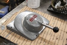
First, I dabbed a touch of grease on the lever pivot, and dropped it into place.

rivett133.jpg

Then another dab of grease, and the gear gets pressed back on- there's a setscrew that retains it, and that assembly is what 'locks' the lever to the cover plate.

rivett134.jpg

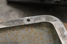
One interesting little bit- there was apparently a void in the casting around one of the cover plate mounting holes. As the plate was otherwise acceptable, they filled the void in with epoxy.

rivett135.jpg

Anyway, all that was left were the two detents- the one at the bottom that just contacts that movable "indicator bar", and the one from the front that centers the lever assembly in the "off" position.

rivett136.jpg

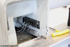
Then, the whole 'rheostat' assembly simply plunks back into place, with the three screws and one spacer.

rivett137.jpg

Hook the four wires back up- hopefully in order- to the bus bar...

rivett138.jpg

And bolt the whole assembly back into place, using some fresh stainless screws from my stashes. (The originals were kinda hammered.)

rivett139.jpg

Not sure what I'm going to do with the indicator plate just yet. I tweaked it back into shape, so it better conforms to the cylinder, but it was originally nickel-plated, and most of that has worn off. The engraving is nice and deep, though, so kind of toying with the idea of just sanding it smooth and uniform, then filling in the lettering with black paint.

But, that's a trick for another day. At the moment, we are now- hopefully- back up to electrically complete, so it's time to try this thing! First, power up the VFD...

rivett140.jpg

And start it- yes, according to the arrow on the AC motor...

rivett141.jpg

It is indeed turning the correct direction. The roller-chain shaft coupler can be seen through the grille, itself barely seen at the lower right, to verify that.

So, with nothing better to do, it was time to try out the drive- and lo and behold, it worked! And, almost exactly two weeks- almost to the hour- from when it first landed on my slab. :)

rivett142.jpg

Can't really tell, but the motor was spinning nicely in there, at probably around 1,000 RPM at a guess.

But, there's definitely some noise in the drive.

rivett143.jpg

That (empty) left-hand pulley? It sounds like the bearing has a definite "click" to it, almost a "rod knock" noise. Not "death rattle" loud, but yeah, it's gonna need to be replaced before too long.

Apart from that, the speed control works smoothly and basically perfectly. I can run it at about 20 RPM (no idea how much torque it'd have at that speed) all the way up to whatever this belt setting is- about 3K, I think?

Then, I threw the spindle belts on to gave that a try:

rivett144.jpg

The spindle wasn't as loud as I expected, but there, too, is a definite 'whirr'. I could probably run it as-is for a time, without any significant issues, but really, the rest of the work, save for getting the actual tooling set up, is basically done. There's not much left to do BUT the bearings and various tool slides.

rivett145.jpg

But for now, it's time to clean up, set this aside (sort of) and catch up on my other work. I'll still be poking around with it as I have time and inspiration- I've been doin' some tool-horsetradin' in the background :D - but the major work is finally done. :)

Doc.
 
OP
D

DocsMachine

Well-known member
Joined
Sep 16, 2006
Messages
1,874
We're still a good ways from 'done' on this machine, and one of the more important things it still needs, is some tooling. I'm hoping to have the time this weekend to start cleaning up the turret, but in the meantime, I got in a new toy for it.

The machine came with a single axis lever-operated cross slide, that was either shop-made at some point (although moderately well done if so) or came off a much smaller lathe, something like a watchmakers' or similar.

I had been hoping I could use the comparatively heavy-duty slide off the little 'speed' lathe, but the bed geometry is quite a bit different. However, while idly looking for Hardinge parts on eBay, I found one of their slides that fit the older "split" beds, which had a geometry a lot closer to that of this Rivett. The seller provided several clear photos, and the price was decent enough I thought I could modify it, so I took a risk on it.

It had been disassembled for shipping, but it looks almost identical to the one on the HSL:

HSL-048.jpg

And, I had to disassemble it anyway, as the bed profile was close, but not a match.

rivett146.jpg

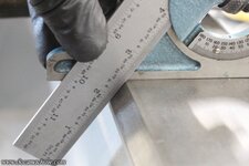
It also appeared the angles weren't quite the same, either. I'd assumed they were 45° facets, but as it turns out, not quite. With the aid of a machinists' protractor...

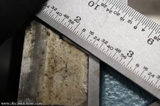
rivett147.jpg

The faces proved to be 55°, while the new casting was the expected 45.

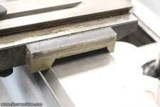
rivett148.jpg

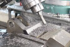
Using the same protractor, I kicked the head of the mill over to cut both faces to both the correct angle and spacing.

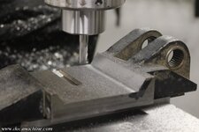
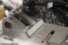
rivett149.jpg

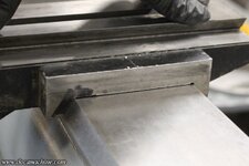
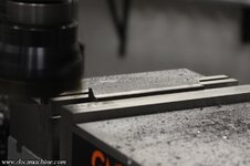
A quick trip over to the other mill smoothed out the 'stairstep' at the bottom face of the cut- since the angled face had to be pushed back almost 3/8".

rivett150.jpg

There was more cut-and-try than I've shown here, but eventually I was happy with the fit, The face angles are spot on, and there's only about 15 thou clearance in the center.

rivett151.jpg

Now, we're going to need a place to attach the bottom halves of the dovetails- the 'clamps'- so I also smoothed and squared up the bottom of the casting on both sides.

rivett152.jpg

Then I found a suitable hunk of steel bar in the bins, and shaved that down 'til it looked about right:

rivett153.jpg

That will attach something like this, with just a few thou of 'crush' in order to clamp to the bedway. (There'll be one on either side, too, of course.)

rivett154.jpg

And that was all I had time for this evening. I need to do some pondering on the front bar, anyway.

Doc.
 

bimmer1980

Well-known member
Joined
Feb 5, 2009
Messages
2,105
Location
York, PA
Nice work on the lathe! I enjoy reading through your methods and projects.

What type of parts will you be running on this lathe?

I have a small Eglin (spl) turret lathe that I bought a number of years ago, but have not really set it up yet.

It has a similar green, peeling, paint on it....ug...
 
OP
D

DocsMachine

Well-known member
Joined
Sep 16, 2006
Messages
1,874
As usual, not much time this evening, but at least managed to get a couple small things done. First things first, I cleaned the green mill off and re-trammed the head back to true and square and plumb and colinear properly fenestrated and all that, then I faced one end of that bar from last night in order to have a reference surface.

rivett155.jpg

Then I measured, spaced out, drilled and countersunk three holes, for some 1/4-20 capscrews.

rivett156.jpg

Those measurements I transferred over to the underside of the slide casting, and drilled and tapped receiving holes.

rivett157.jpg

I didn't have the right size screws, and it was way too late to hit up Homey-Dee, so I found a couple of countersunk ones that'll work to test fit the assembly.

rivett158.jpg

And, if I do say so myself, it's frikkin' perfect. :)

rivett159.jpg

The assembly slides on from the end, very smoothly, no binding, and yet I can feel basically zero slop. I can lift the front edge- no clamp, of course- but I can't even wiggle the back.

rivett160.jpg

Which is perfect- when it comes time to finish this thing, if I need to tighten up the fit a touch, I can shave off- or more likely just surface grind off- a couple of thousandths and give it just a touch of "clamp".

One other thing I did was I started dismantling the turret...

rivett161.jpg

... So that hopefully over the course of this coming week, I can start getting those parts cleaned up, stripped and painted.

It's slow going, but kicking the can along as best I can. More on the way! :)

Doc.
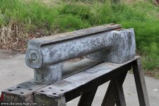
 
OP
D

DocsMachine

Well-known member
Joined
Sep 16, 2006
Messages
1,874
What type of parts will you be running on this lathe?

-Small ones. :)

I produce and sell my own parts, but in fairly small numbers- fifty is a decent run, and two hundred is a huge one. I have a CNC turning center, but I also get a fair bit of use out of a biggish Warner & Swasey turret lathe.

The problem with that, though, is a fairly slowish spindle (max of 1,400 RPM, 700 is more normal) and a heavy turret, neither of which do well with tiny drills or taps.

This one will have a much more sensitive turret feed, and a considerably faster spindle- supposedly up to 4,800 RPM. Both of which will be ideal for small drills and such.

Doc.
 
To avoid these ads, REGISTER NOW!
Top Bottom