To avoid these ads, REGISTER NOW!

Logan 922 ca.1951 Restoration

To avoid these ads, REGISTER NOW!

duke5572

Well-known member
Joined
Aug 24, 2008
Messages
313
Location
Council Bluffs, IA
I really enjoy these threads even though they're way beyond my knowledge and ability. Something about big metalworking machines is fascinating. This one isn't quite AP_Mech level of crazy detail, but extremely nice nonetheless. Thank you for documenting your progress and sharing it with everyone!
 

2oolhound

Well-known member
Joined
Dec 18, 2010
Messages
5,918
Location
BC Canada
Thanks for the post, I really enjoyed watching your progress although I found it difficult to try to take seriously with that Benny Hill avatar. :lol:
 
OP
O

OldeTimeEtc

Well-known member
Joined
Aug 16, 2014
Messages
478
Location
Palm springs area in S. Calif
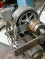
Finally.......just got the parts I've been needing to finish the lathe. Two parts I've been needing is the countershaft bracket and cone pulley. Both were damaged on the lathe so I found a replacement for the bracket and had the cone pulley repaired along with the replacement that needed some work. First the replacement bracket I found on Evilbay that was included in a lot buy along with an extra motor and the entire back drive backets of the same Logan lathe. Fortunately the seller was in driving distance so I had to go pick it up. Had to buy the entire lot since he wouldn't part it out.
 

Attachments

  • $_57f.JPG
    $_57f.JPG
    83.6 KB · Views: 26
OP
O

OldeTimeEtc

Well-known member
Joined
Aug 16, 2014
Messages
478
Location
Palm springs area in S. Calif
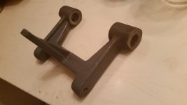
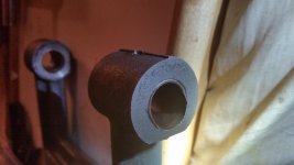
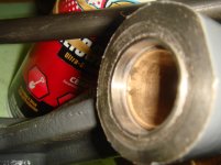
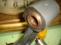
Upon removing the bracket I found that it was in decent shape but unfortunately the last operator let the lathe run without lube which the shaft finally wore an oblong hole right thru the bushing on one side of the bracket.
 

Attachments

  • DSC01896.jpg
    DSC01896.jpg
    133.5 KB · Views: 19
  • 20150610_210734.jpg
    20150610_210734.jpg
    141.9 KB · Views: 20
  • 20150610_204911.jpg
    20150610_204911.jpg
    144.5 KB · Views: 20
OP
O

OldeTimeEtc

Well-known member
Joined
Aug 16, 2014
Messages
478
Location
Palm springs area in S. Calif
Since the other bracket had more damage, the only best option I had was to have this one repaired. So I took it to a local machinist and had the damaged hole precision milled and a sleeve made and inserted to repair the hole and then replaced the bushings with new ones I had already purchased from Logan. Only thing I had to do myself was redrill the oiling holes thru the new bushings.
 

Attachments

  • DSC02086.jpg
    DSC02086.jpg
    135.9 KB · Views: 16
  • DSC02114.jpg
    DSC02114.jpg
    125.8 KB · Views: 9
Last edited:
OP
O

OldeTimeEtc

Well-known member
Joined
Aug 16, 2014
Messages
478
Location
Palm springs area in S. Calif
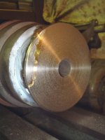
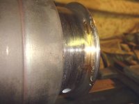
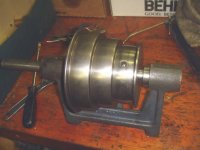
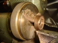
Next was the cone pulley. Both had a piece cracked off the side so I had them repaired by rebrazing. I then took one and chucked it up in my smaller lathe then resurfaced the face to remove all excess braze.
 

Attachments

  • DSC02080.jpg
    DSC02080.jpg
    136 KB · Views: 20
  • DSC02081.jpg
    DSC02081.jpg
    135.7 KB · Views: 20
  • DSC02079.JPG
    DSC02079.JPG
    136.3 KB · Views: 16
Last edited:
OP
O

OldeTimeEtc

Well-known member
Joined
Aug 16, 2014
Messages
478
Location
Palm springs area in S. Calif
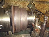
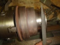
Next was the long slow process of removing the excess brass inside the pulley channel. Using several metal cutting bits on my dremel, several fine files and my lathe and removing small amounts at a time I eventually restored it to its original shape. After final sanding and polishing and I had a new pulley. Even ran a dowel wrapped in fine sanding paper thru its center hole to remove any roughness.
 

Attachments

  • DSC02085.JPG
    DSC02085.JPG
    137.8 KB · Views: 19
  • DSC02083.jpg
    DSC02083.jpg
    145.1 KB · Views: 16
  • DSC02084.jpg
    DSC02084.jpg
    132 KB · Views: 16
  • DSC02082.jpg
    DSC02082.jpg
    143.2 KB · Views: 16
OP
O

OldeTimeEtc

Well-known member
Joined
Aug 16, 2014
Messages
478
Location
Palm springs area in S. Calif
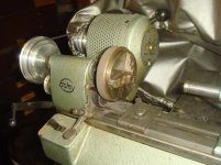
Now a test fit. I installed the parts on the lathe to align the pulleys and mark the set screw positions. Next I have to remove everything to mill a flat area on the shaft for the setting screws..then painting before final install.
 

Attachments

  • DSC02088.JPG
    DSC02088.JPG
    145 KB · Views: 21
  • DSC02089.jpg
    DSC02089.jpg
    139.5 KB · Views: 23
Last edited:
FJ 432

Well-known member
Joined
Aug 2, 2010
Messages
3,737
Location
Littleton Colorado
I know little to nothing about lathes although they fascinate me.

I do know a little about technical writing and the work you placed on documenting your steps was outstanding. Your work to produce this thread probably added 30-40% of your time on this restoration. Bravo sir and thanks in advance from the people who will gain from your time.
 
OP
O

OldeTimeEtc

Well-known member
Joined
Aug 16, 2014
Messages
478
Location
Palm springs area in S. Calif
Tonight I got busy aligning and marking the pulleys for their set screws.

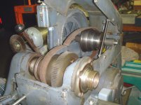
The new shaft I had purchased earlier from Logan I found is a might longer then the factory one so I had to make sure it didn't project out too much on the left side of the lathe where the guard door covers the main drive v-belt pulleys. I had to make sure there was enough clearance so the shaft wouldn't grind into the guard door. Using another straight edge helped to see and gage how close the shaft came to the inside of the door and still had room to adjust the upper large v-belt pulley in and out to align it with the lower one mounted to the motor. Using a machinists square helped me with that adjustment. I still left enough space to make micro adjustments later if needed. Once I had that set right...on to the cone pulley.
 

Attachments

  • DSC02097.jpg
    DSC02097.jpg
    133.3 KB · Views: 10
  • DSC02096.jpg
    DSC02096.jpg
    123.1 KB · Views: 10
Last edited:
OP
O

OldeTimeEtc

Well-known member
Joined
Aug 16, 2014
Messages
478
Location
Palm springs area in S. Calif
First I found something long enough to use as a straight edge and once I had the rear cone pulley exactly aligned and parallel with the front I then "marked" its position by sliding and tightening the set screw on a collar butted up against the pulley. I also marked the shaft on the outside with a sharpie and made wrote an "R" for right so I know which side so I could remember and return it to its original position once I reinstall everything.
 

Attachments

  • DSC02094.JPG
    DSC02094.JPG
    135.3 KB · Views: 12
  • DSC02091.jpg
    DSC02091.jpg
    133.6 KB · Views: 10
  • DSC02093.jpg
    DSC02093.jpg
    125.4 KB · Views: 10
  • DSC02090.jpg
    DSC02090.jpg
    140.1 KB · Views: 10
OP
O

OldeTimeEtc

Well-known member
Joined
Aug 16, 2014
Messages
478
Location
Palm springs area in S. Calif
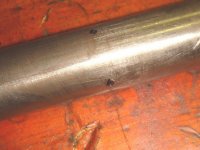
Now that I had the bracket removed and the pulley position "marked" I then made a light punch mark on the shaft thru the set screw holes and then once I removed the shaft from the pulley I highlighted the punch marks with a sharpie. Next is milling the flats for the set screws but right now its 5am and I'm tired so I'll continue this later.
 

Attachments

  • DSC02099.jpg
    DSC02099.jpg
    127.9 KB · Views: 14
  • DSC02101.jpg
    DSC02101.jpg
    138.6 KB · Views: 10
To avoid these ads, REGISTER NOW!
OP
O

OldeTimeEtc

Well-known member
Joined
Aug 16, 2014
Messages
478
Location
Palm springs area in S. Calif
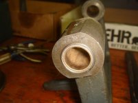
Once done with painting the Bracket and Cone Pulley, I turned my attention to something I've had on my mind for while that was also bugging me. When I purchased new bushings for the counter bracket I noticed they don't extend the full length of the bracket hole. Now why Logan doesn't provide a longer bushing puzzles me and weather or not its really necessary isn't the issue....least to me. I just felt the extra length would not only look more pleasing mechanically and looks-wise, but also the added bushing surface certainly couldn't hurt.
 

Attachments

  • DSC02103.jpg
    DSC02103.jpg
    127.1 KB · Views: 13
OP
O

OldeTimeEtc

Well-known member
Joined
Aug 16, 2014
Messages
478
Location
Palm springs area in S. Calif
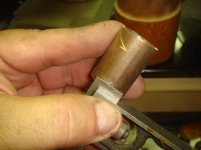
So I took a measurement of how much more I'd need and transferred that measurement with a pencil line to an extra bushing I had. Rather than taking a precise cut on a lathe to fit flush I decided to short cut this and cut it a might longer and grind it down flush with a find cutting disc on my Foredom tool. So I chucked up the bushing on my Boley Lathe and cut me 2 rings off each end of the bushing so I'd have at least one square end to **** up against the other bushing already in the hole.
 

Attachments

  • DSC02113.jpg
    DSC02113.jpg
    135.6 KB · Views: 7
  • DSC02112.jpg
    DSC02112.jpg
    138.8 KB · Views: 9
  • DSC02111.jpg
    DSC02111.jpg
    136.5 KB · Views: 8
  • DSC02108.jpg
    DSC02108.jpg
    142.6 KB · Views: 7
  • DSC02109.jpg
    DSC02109.jpg
    128.9 KB · Views: 7
  • DSC02110.jpg
    DSC02110.jpg
    134 KB · Views: 7
  • DSC02107.jpg
    DSC02107.jpg
    137.6 KB · Views: 9
Last edited:
OP
O

OldeTimeEtc

Well-known member
Joined
Aug 16, 2014
Messages
478
Location
Palm springs area in S. Calif
Once pressed in it was an easy task since the bushing material was so soft, to grind the excess down flush leaving a nice smooth finish and pleasing look.
 

Attachments

  • DSC02106.jpg
    DSC02106.jpg
    131.9 KB · Views: 9
  • DSC02105.jpg
    DSC02105.jpg
    133.9 KB · Views: 10
  • DSC02104.jpg
    DSC02104.jpg
    141.1 KB · Views: 7
  • DSC02116.jpg
    DSC02116.jpg
    132.5 KB · Views: 8
OP
O

OldeTimeEtc

Well-known member
Joined
Aug 16, 2014
Messages
478
Location
Palm springs area in S. Calif
The shaft was still a might snug so I then chucked up the new shaft using my Craftsman Lathe to hold it while wiping off the shaft all the while replacing it with fresh oil thru the bushings and turning the chuck by hand till it turned free.
 

Attachments

  • DSC02117.jpg
    DSC02117.jpg
    143.2 KB · Views: 10
OP
O

OldeTimeEtc

Well-known member
Joined
Aug 16, 2014
Messages
478
Location
Palm springs area in S. Calif
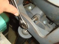
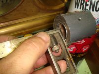
Finally I permanently installed the Counterbracket on the Lathe first putting a small amount of grease where it pivots on the pivot screws and then adjusting it center in the drive box. Once I was happy with its position I tightened the screw's Jam nuts to lock them in place.
 

Attachments

  • DSC02123.jpg
    DSC02123.jpg
    131.2 KB · Views: 13
  • DSC02122.jpg
    DSC02122.jpg
    135.5 KB · Views: 11
  • DSC02121.jpg
    DSC02121.jpg
    138.5 KB · Views: 12
  • DSC02120.jpg
    DSC02120.jpg
    135.1 KB · Views: 12
Last edited:
OP
O

OldeTimeEtc

Well-known member
Joined
Aug 16, 2014
Messages
478
Location
Palm springs area in S. Calif
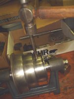
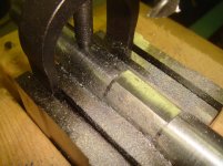
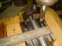
Tonight I started work on the final part of my lathe to complete it... the counter bracket drive shaft. I needed to mill some flats on the shaft where the set screws mate with the shaft for added strength and also its less likely to slip on the shaft or come loose. Since I don't have a mill yet I had to improvise a rig I made for my drill press. Taking a set of V Blocks with hold-downs I make a jig out of scrape wood to hold them in a straight line. So after using a small drill as a "centering" guide I then C-clamped the whole jig tightly to my drill press table. I also checked to see if it was centered to the shaft where I had already marked with a sharpie the areas I needed to mill.
 

Attachments

  • DSC02126.jpg
    DSC02126.jpg
    140.5 KB · Views: 13
  • DSC02125.jpg
    DSC02125.jpg
    136.4 KB · Views: 11
Last edited:
OP
O

OldeTimeEtc

Well-known member
Joined
Aug 16, 2014
Messages
478
Location
Palm springs area in S. Calif
Once I was sure I had my work laid out straight and centered. I chucked up a small mill cutter and with a light dab of cutting lube I made small cuts along the 1" long area I had marked. This gave me the option to fine tune the alignment to the front pulley where I could make some fine adjustments left or right if needed. After making my cuts with the mill bit I finished it off by using a fine flat file. I must say it turned out pretty nice. In all I cut 2 flat areas for the set screws on the cone pulley and one near the left end where the large upper V Belt pulley is mounted to the shaft.
 

Attachments

  • DSC02127.jpg
    DSC02127.jpg
    145.7 KB · Views: 9
  • DSC02128.jpg
    DSC02128.jpg
    140.2 KB · Views: 9
OP
O

OldeTimeEtc

Well-known member
Joined
Aug 16, 2014
Messages
478
Location
Palm springs area in S. Calif
Before installing the shaft and pulleys I marked the center of the flat with a sharpie and slide the shaft into the cone pulley all the while sighting down the set screw holes with a flashlight till I saw my marks. I then made reference marks on the side of the pulley showing me where to align the flats with the set screws. I then installed the drive shaft with the pulley and 2 collars. I lightly snugged down a set screw once it was centered on my marks and checked the alignment of the rear pulley to the front one using a straight edge. Once satisfied it was in its proper position I tightened the set screws on the collars locking the shaft onto the counterbracket and then tightened down the cone pulley's set screws...put some oil into the oil holes on the bracket and gave it a spin......it turned nice and easy....done.
 

Attachments

  • DSC02135.jpg
    DSC02135.jpg
    136.1 KB · Views: 6
  • DSC02134.jpg
    DSC02134.jpg
    137.9 KB · Views: 5
  • DSC02133.jpg
    DSC02133.jpg
    134.7 KB · Views: 7
  • DSC02129.jpg
    DSC02129.jpg
    132.7 KB · Views: 6
OP
O

OldeTimeEtc

Well-known member
Joined
Aug 16, 2014
Messages
478
Location
Palm springs area in S. Calif
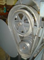
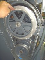
Last...I slid on the upper v belt pulley and once I had its set screw centered with the flat on the shaft I gave it a just a light down so I could check the v belt's alignment with the lower pulley. After a few adjustments in and out I had the pulleys aligned perfectly and tightened its set screw down. I then had to make a few adjustments on the motor mount to take up the slack of the v belt which only took a few mins. Some final adjustments will need to be made once I order a new flat belt. As a precaution I did recheck the length of the belt required by using a piece of string wrapped around the pulleys and then measuring it's length. Logan's parts list require a 40" long belt for both the v belt and flat one.....I just wanted to be sure. Luckily the V-belt that came with the lathe is still in great shape and the right length......so all I need to buy is a new flat belt.
 

Attachments

  • DSC02140.jpg
    DSC02140.jpg
    136.4 KB · Views: 9
  • DSC02139.jpg
    DSC02139.jpg
    139.3 KB · Views: 10
  • DSC02137.jpg
    DSC02137.jpg
    137.6 KB · Views: 9
  • DSC02138.jpg
    DSC02138.jpg
    137 KB · Views: 10
OP
O

OldeTimeEtc

Well-known member
Joined
Aug 16, 2014
Messages
478
Location
Palm springs area in S. Calif
Even though the lathe is finally complete its far from finished.....I'll still need to make several adjustments to the belt drives and still need to disassemble the chuck and restore it. Plus theres a few other things I still need to do......so stay tumed.
 
OP
O

OldeTimeEtc

Well-known member
Joined
Aug 16, 2014
Messages
478
Location
Palm springs area in S. Calif
Well ordered the new flat belt this morning and if everything works out like its suppose to I'll have a great source and helluva deal for you guys to get custom made flat belts cheap but I'll reserve that till after I receive mine and make sure everythng goes as told by the source before I go sending others there....I'll start another thread on that subject if it turns out well and the product is top notch.....I'm sure it will be but I'm just being cautious.
 
OP
O

OldeTimeEtc

Well-known member
Joined
Aug 16, 2014
Messages
478
Location
Palm springs area in S. Calif
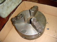
So seeing as my new flat belt is on its way I decided to get started on the 3 jaw chuck disassembly and cleaning. The chuck that came with the lathe was made by the Union Mfg Co of New Britain, Conn
 

Attachments

  • DSC02142.jpg
    DSC02142.jpg
    140.5 KB · Views: 12
  • DSC02159.jpg
    DSC02159.jpg
    147.8 KB · Views: 14
Last edited:
OP
O

OldeTimeEtc

Well-known member
Joined
Aug 16, 2014
Messages
478
Location
Palm springs area in S. Calif
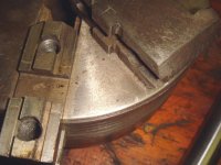
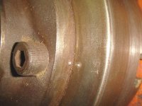
First removal of the reversible Jaws. To my delight all the jaw positions and their mating parts had number stamps so I didn't need to mark anything to remember what goes where.
 

Attachments

  • DSC02143.jpg
    DSC02143.jpg
    144.3 KB · Views: 7
  • DSC02145.jpg
    DSC02145.jpg
    140.5 KB · Views: 7
  • DSC02146.jpg
    DSC02146.jpg
    138 KB · Views: 7
  • DSC02147.jpg
    DSC02147.jpg
    121.6 KB · Views: 8
OP
O

OldeTimeEtc

Well-known member
Joined
Aug 16, 2014
Messages
478
Location
Palm springs area in S. Calif
Next the back spindle mounting plate but first I marked its position so it goes back exactly in the same way.
 

Attachments

  • DSC02149.jpg
    DSC02149.jpg
    137.8 KB · Views: 10
  • DSC02148.jpg
    DSC02148.jpg
    145.8 KB · Views: 9
Last edited:
OP
O

OldeTimeEtc

Well-known member
Joined
Aug 16, 2014
Messages
478
Location
Palm springs area in S. Calif
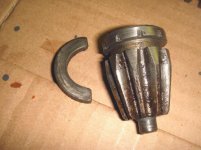
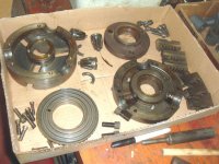
Next the main body and again I marked the pinion gears position .....1 mark - 3 marks....so they went back to their original positions. I reason I mark parts to return them to their original places I feel because they have already "worn in" or been broken in to those places and best to return them to their original places. Its my own personal feeling and preference. I also kept the gear's retaining rings together with their original gear. Tapped out the scroll and it was a snap taking the chuck apart. I was surprised it was pretty clean internally seeing as how old it was.
 

Attachments

  • DSC02151.jpg
    DSC02151.jpg
    136.6 KB · Views: 8
  • DSC02152.jpg
    DSC02152.jpg
    147.5 KB · Views: 10
  • DSC02153.jpg
    DSC02153.jpg
    143.5 KB · Views: 8
  • DSC02154.jpg
    DSC02154.jpg
    145.9 KB · Views: 8
  • DSC02155.jpg
    DSC02155.jpg
    143.1 KB · Views: 8
Last edited:
OP
O

OldeTimeEtc

Well-known member
Joined
Aug 16, 2014
Messages
478
Location
Palm springs area in S. Calif
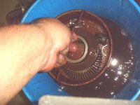
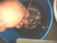
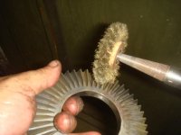
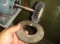
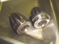
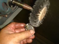
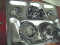
As I have mentioned before these smaller fine stainless and brass wire brushes for my buffing machine are indispensable for getting into close areas and between gear teeth for cleaning up residual crud and surface rust without cutting into the metal leaving a nice finish unlike large coarse wire wheels. Two pinion gears I have pictured are before and after cleaning up.
 

Attachments

  • DSC02165.jpg
    DSC02165.jpg
    132 KB · Views: 12
  • DSC02164.jpg
    DSC02164.jpg
    130.3 KB · Views: 11
  • DSC02163.jpg
    DSC02163.jpg
    140.6 KB · Views: 11
  • DSC02160.jpg
    DSC02160.jpg
    136.1 KB · Views: 13
  • DSC02162.jpg
    DSC02162.jpg
    127.4 KB · Views: 9
Last edited:
OP
O

OldeTimeEtc

Well-known member
Joined
Aug 16, 2014
Messages
478
Location
Palm springs area in S. Calif
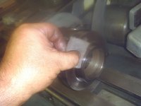
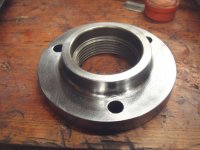
The back spindle mounting plate I did a preliminary satin polish on my Scotch Brite Wheel then a finish spin on my smaller lathe. I could have sanded it smoother and gotten a brighter finish but decided against it.
 

Attachments

  • DSC02166.jpg
    DSC02166.jpg
    140.9 KB · Views: 9
  • DSC02167.jpg
    DSC02167.jpg
    134.3 KB · Views: 8
  • DSC02170.jpg
    DSC02170.jpg
    137.1 KB · Views: 11
Last edited:
OP
O

OldeTimeEtc

Well-known member
Joined
Aug 16, 2014
Messages
478
Location
Palm springs area in S. Calif
Half the parts are done.....the jaws I decided to just do a surface cleaning with a fine stainless wheel to remove the metal "age stains" and left the machined surfaces alone.
 

Attachments

  • DSC02171.jpg
    DSC02171.jpg
    137.8 KB · Views: 12
OP
O

OldeTimeEtc

Well-known member
Joined
Aug 16, 2014
Messages
478
Location
Palm springs area in S. Calif
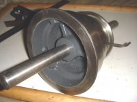
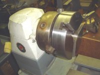
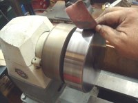
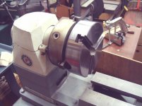
The next half of parts I started with the main front and rear housing of the chuck body. Since it was too small for my small craftsman 6" lathe to chuck up for polishing I used my variable speed Rockwell wood lathe's 3 jaw chuck which did nicely since it would hold a larger piece. Once I had it mounted securely I spun it at about 1/2 speed and went over just the outside of the body mainly with a fine sandpaper for cosmetic reasons to give it a nice finished look. Then finished it off with some scotch brite. I repeated this with the rear half of the chuck housing. Just finishing the outside surface and leaving the machined areas alone.
 

Attachments

  • DSC02173.jpg
    DSC02173.jpg
    132.3 KB · Views: 14
  • DSC02175.JPG
    DSC02175.JPG
    89.7 KB · Views: 14
  • DSC02172.jpg
    DSC02172.jpg
    131.2 KB · Views: 15
Last edited:
To avoid these ads, REGISTER NOW!
Top Bottom