lomonte
Well-known member
Wheeee! New toys!


I'm not even qualified to comment. I'm just in awe of your work, Robert.


") , I'm guessing you're using a tripod? I look forward to reading your posts.
, I'm guessing you're using a tripod? I look forward to reading your posts.The work speaks for itself, but the camera work really makes this thread special! What are you using? Based on the many blurry shots in my thread
Canon SX120is. I've had better luck with the Canon point and shoots in taking the "occasional" bounce on the shop floor. This one's probably going on 3-4 years old, so that's about a record here in camera life..I've also had a few blurry shots with it, no tripod here but I am getting better at the one-handed camera operation.
I see you are really getting into the metal fab and going to lessons too. That is something I'd like to do when I have more time, but then you do a lot more fab than me - while I need to turn out finished cars - LOL!! Was the Baleigh course part of the contest you won? Did you get your winnings yet?
I've been wanting to go to a few, but the scheduling stars never aligned. I went to Gatormeet this year (finally) and picked up some new skills that I would have been reluctant to try otherwise. That's the good part of a meet like that, you have projects to work on, everyone can jump in and give a hand, and those that have the experience are there to guide you along. Most of the meets run from one day to up to a week long. I did get an invite to the Baileigh training, it was a one day event but I showed up a bit early and got to meet some of the guys the day before. Shane suggested I look at all the different machines before making my decision on what to get for the contest prize. They go through some of the benefits of one machine over another, show the various features, and have a hands on training for you to try them out. I found it a good experience, especially if you're in the market for some metalshaping machinery it gives you a good opportunity to "kick the tires" and get some training to boot. Should be a short flight for you to Green bay, and about a 1/2 hour drive south from there. PM Shane Henderson on the Hamb and ask him about the next class.
That "kid" Kyle - I'm pretty sure he's the guy on the show FantomWorks - no? I wonder if he still works at FantomWorks, or if he jumped onto his own after the TV exposure? (Funny he always wears that hat - it MUST be filthy!!)
Having shown up early, I got to go out to dinner a couple nights with Kyle and some of the other instructors. Kyle is a real down to earth guy, and is very well versed in metalshaping, and is a much better instructor than he would have you believe. He is no longer with Fantomworks, he has his own shop in Suffolk, VA: http://www.yocumsrodshop.com/ Funny you mention the hat, it was brought up at dinner one night that he should have some of those embroidered with his shop name and sell them on his web site.
Anyways, like many, I come here for inspiration and lessons - so THANK YOU for the great quality of your photo's and sharing some of what you're learning by attending those lessons.
That's the hope, that my posts will be inspirational to help others make the jump into metal shaping or even just improve their skills on a hobbyist level. By sharing the knowledge, the art of metal shaping is carried on to future generations.
Maybe when I'm truly retired, I'll have you out here to put on some lessons in my shop for us Canucks!
You never know where my travels take me!
Cheers!!

Oh ya - GREAT vids! I keep saying: you're moving towards professional tutorials - when's the first DVD planned?!


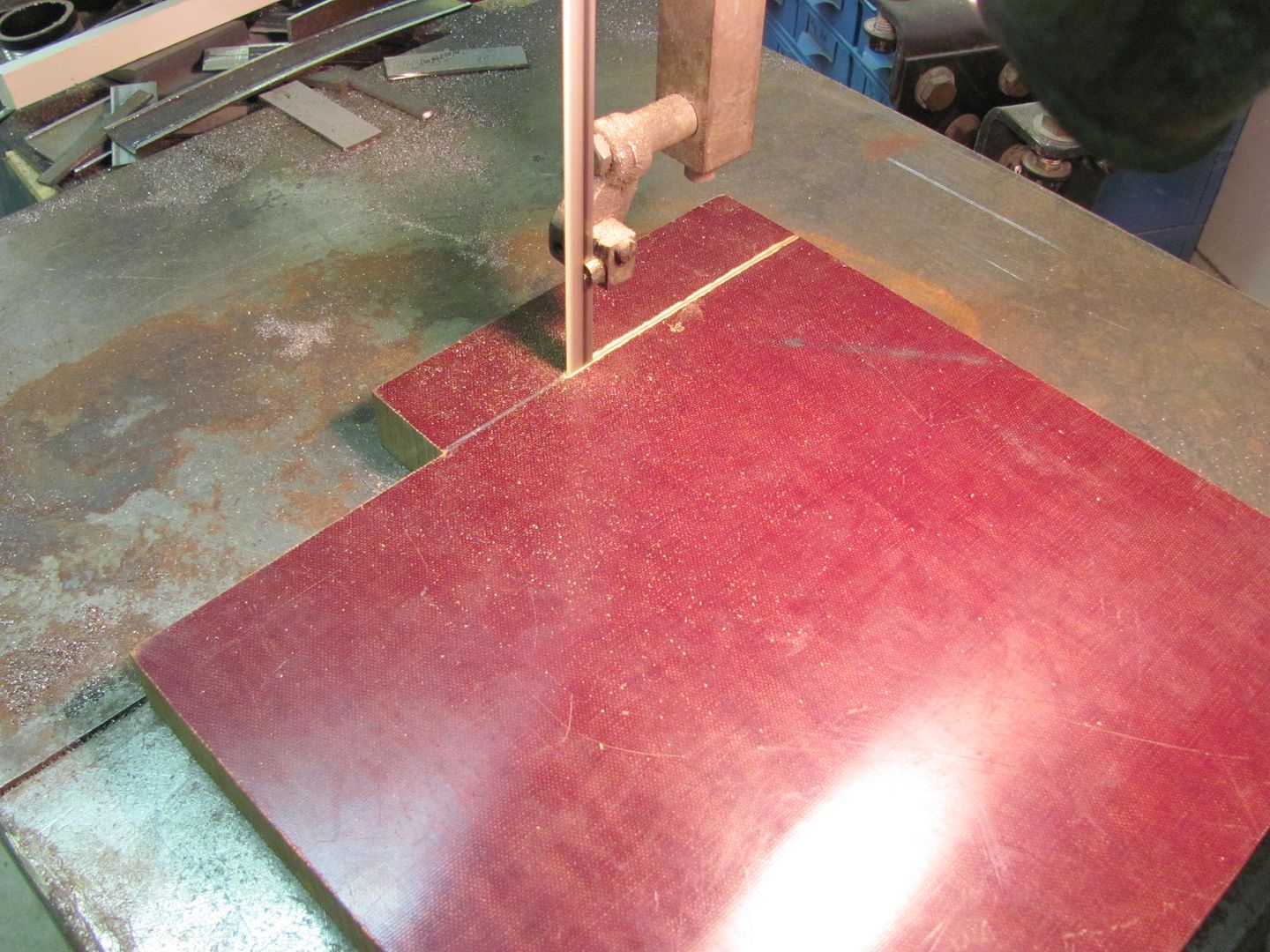
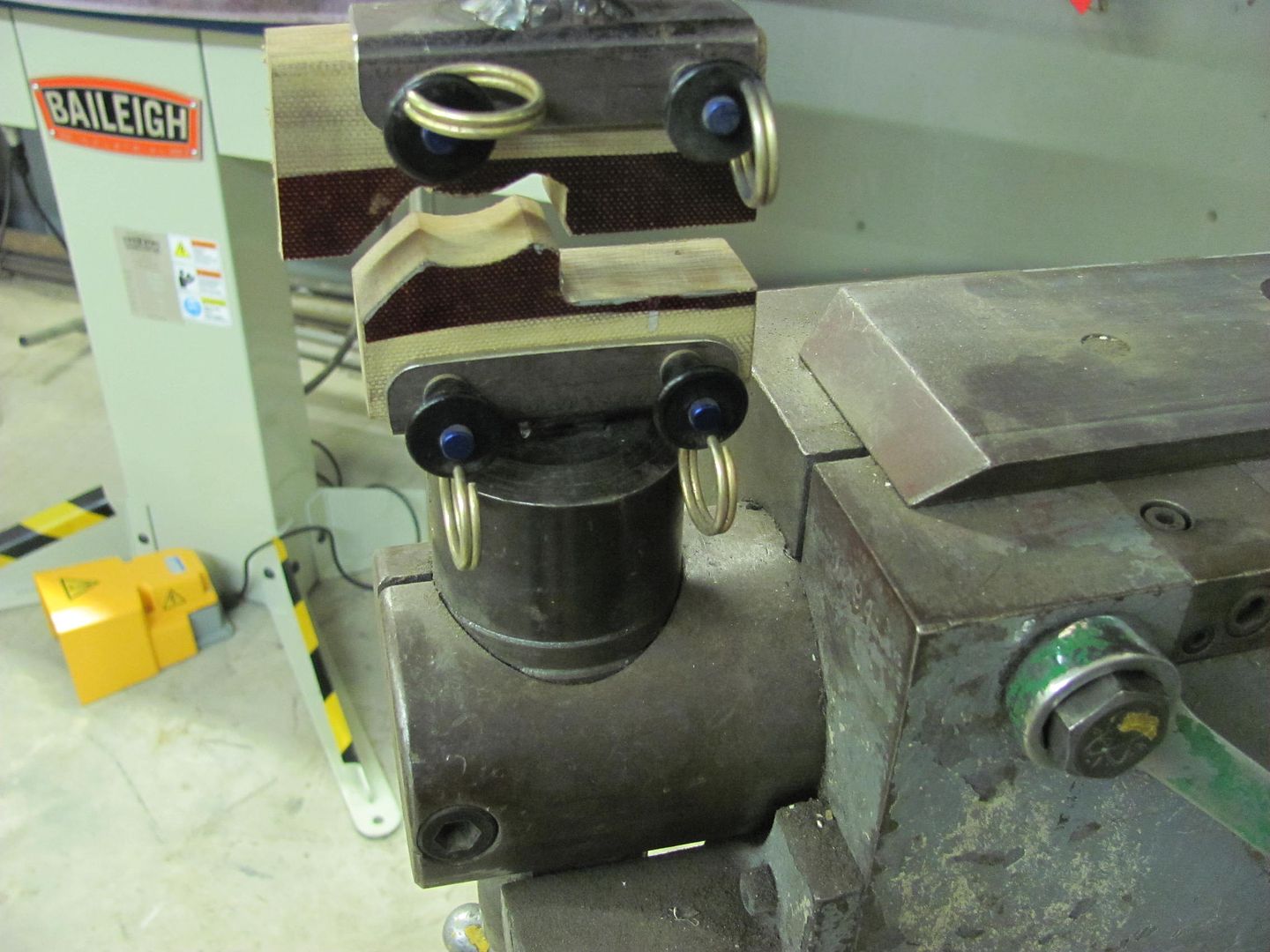
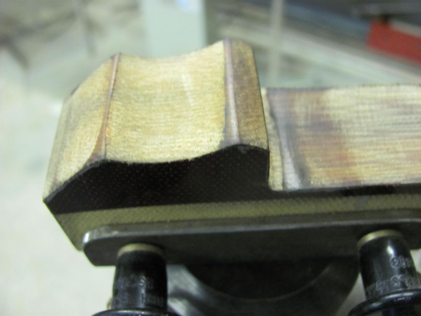
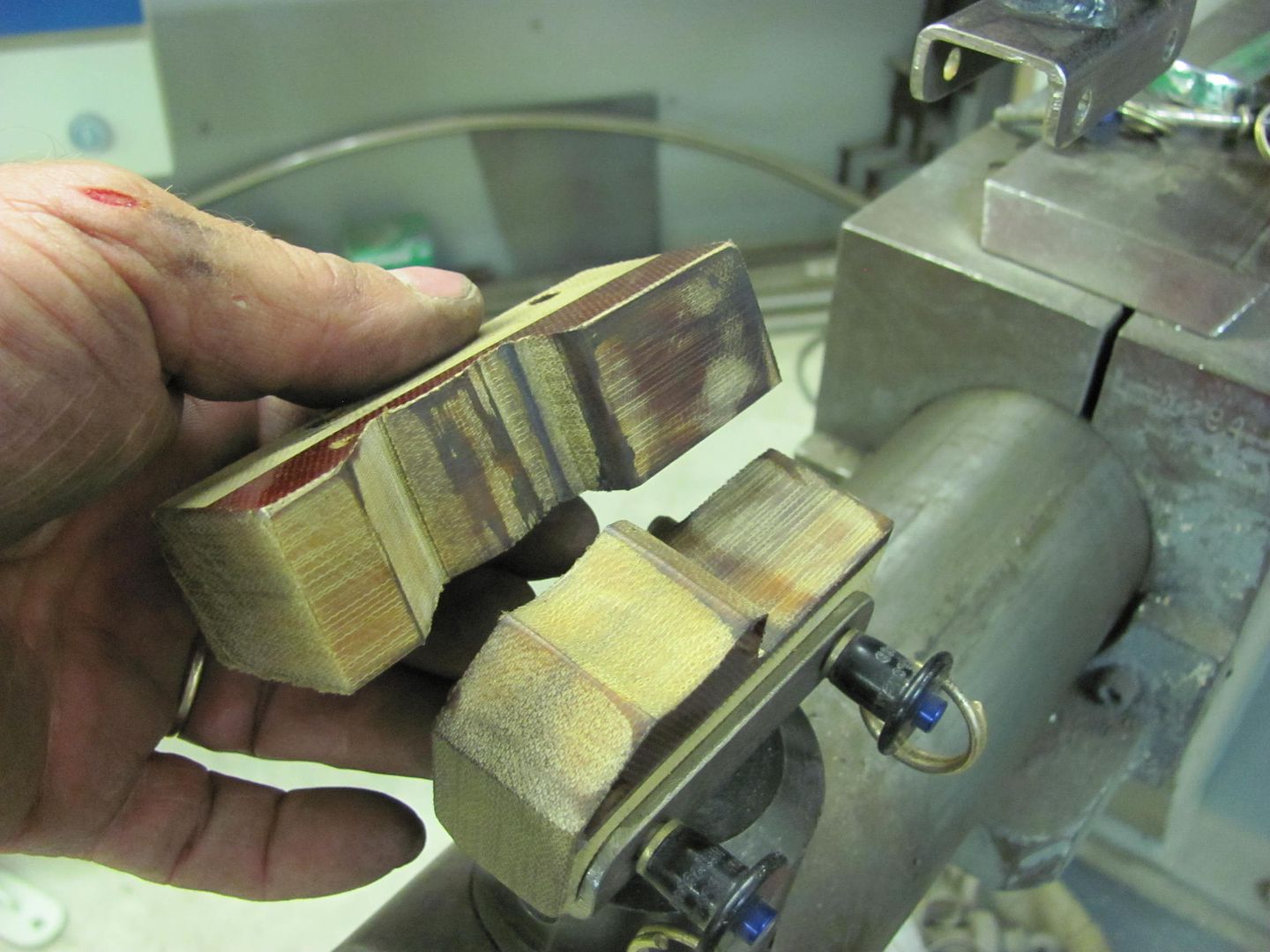
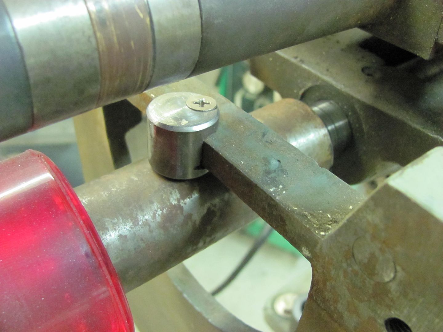
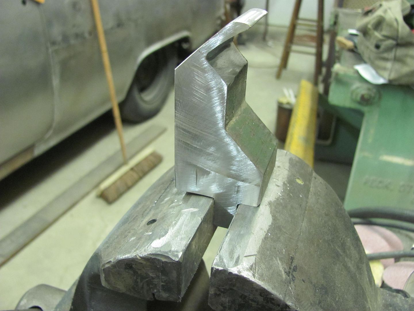
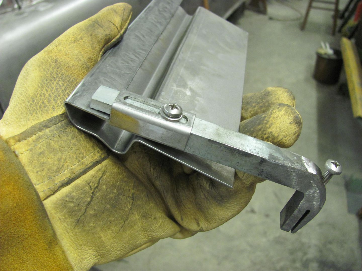
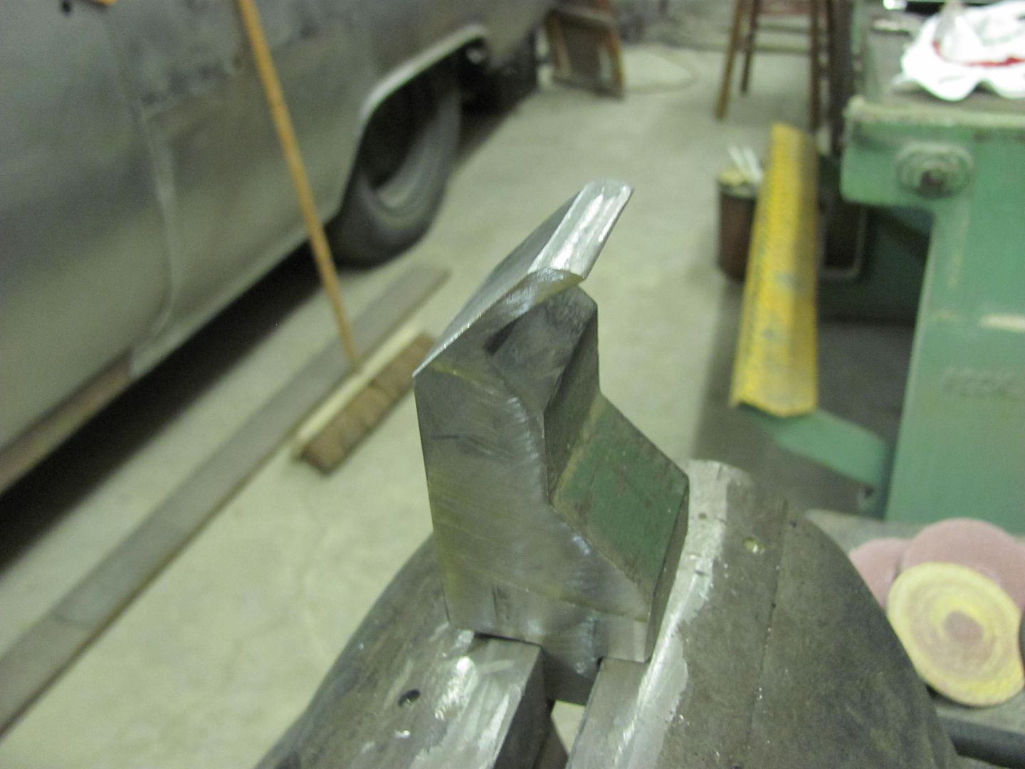
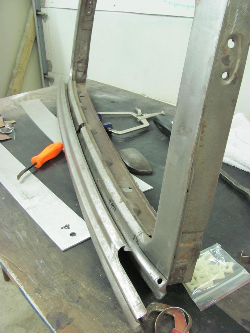
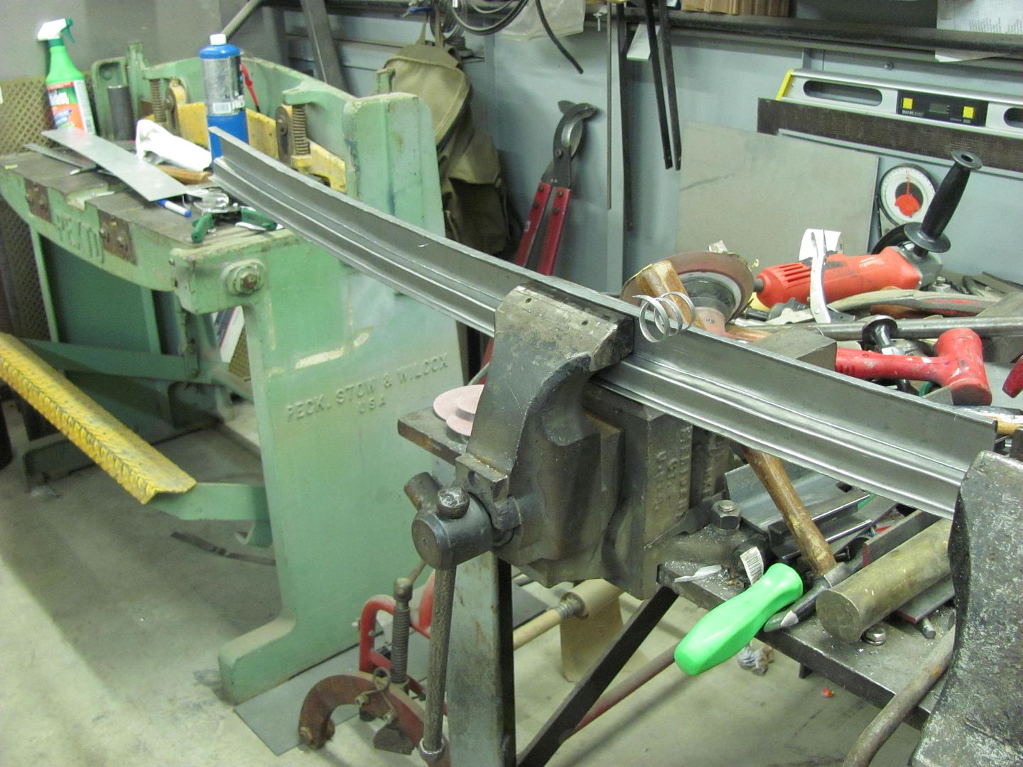
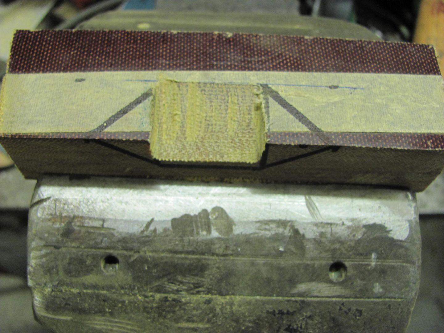
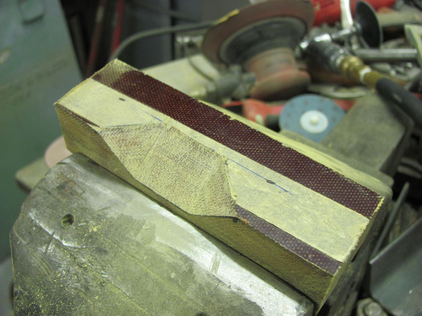
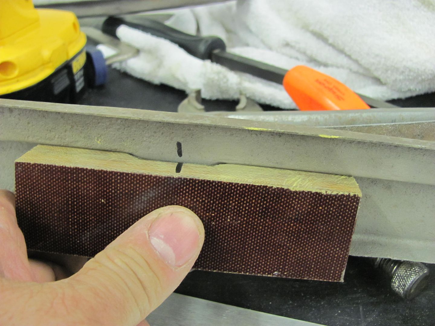
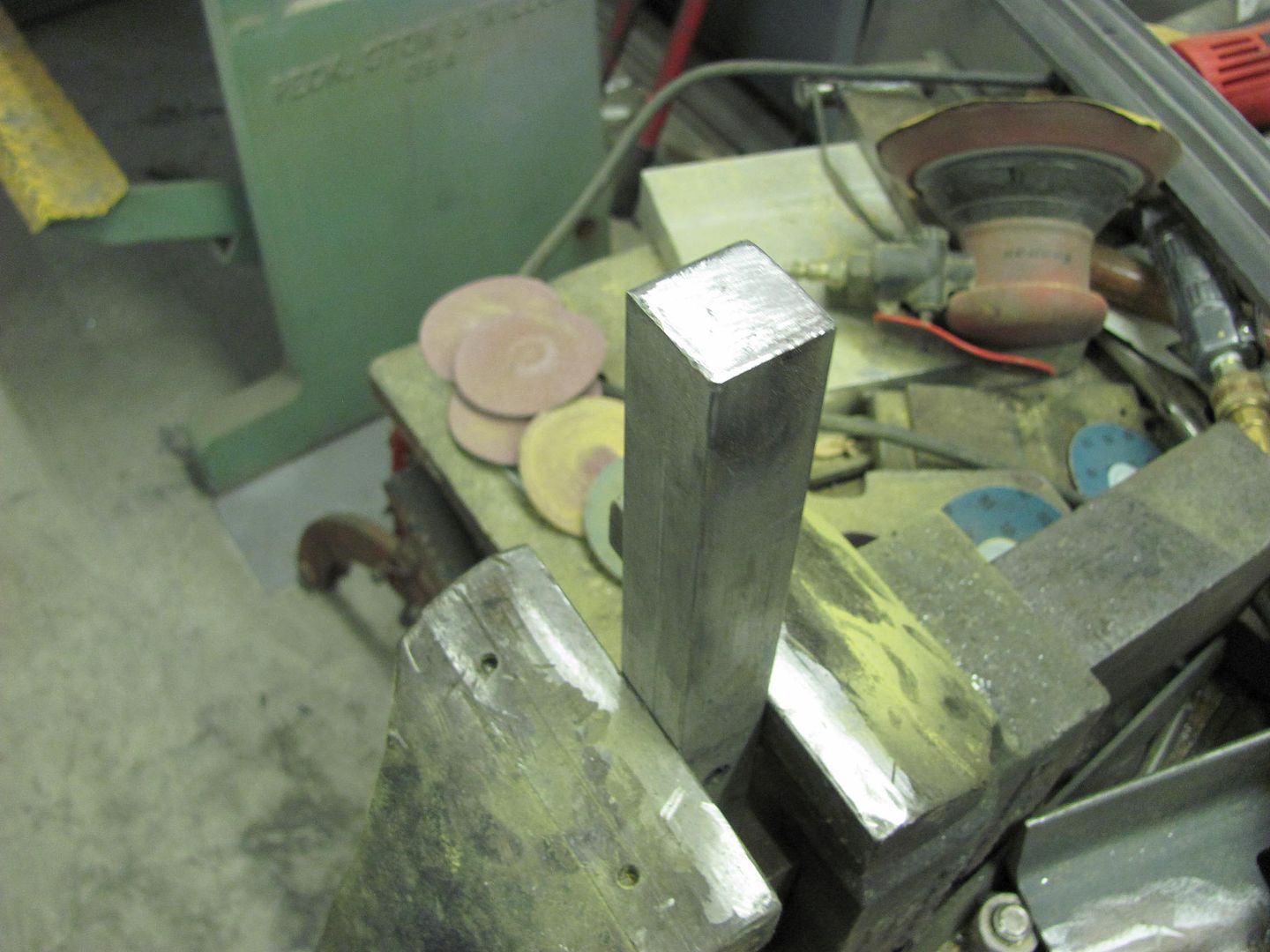
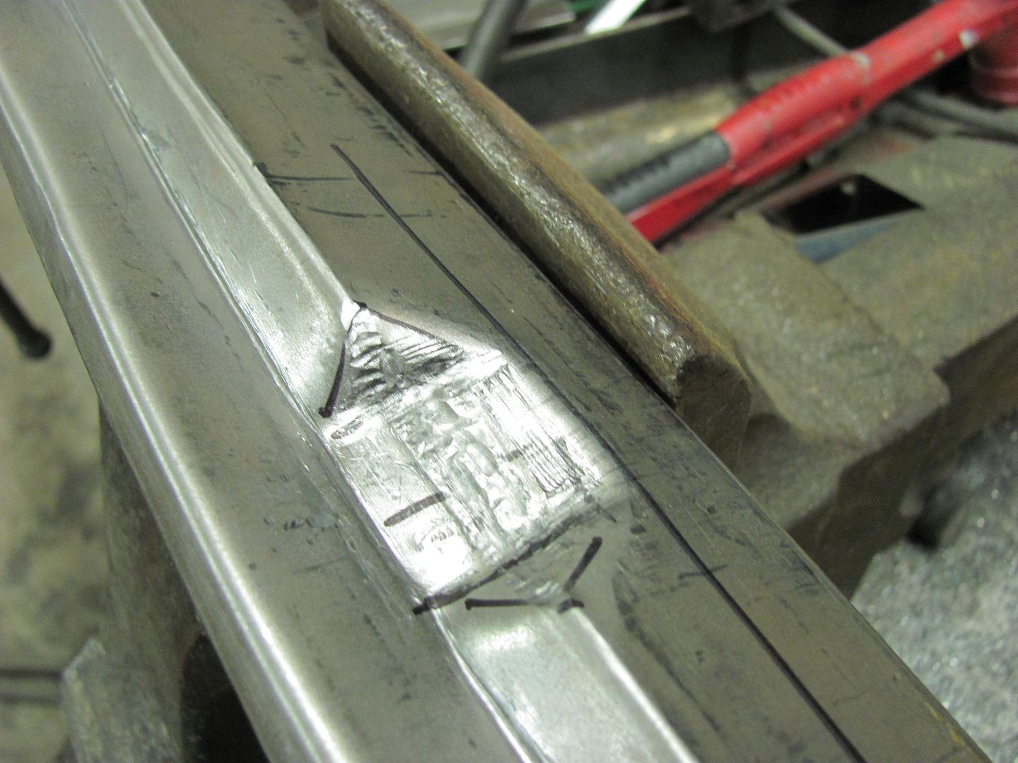
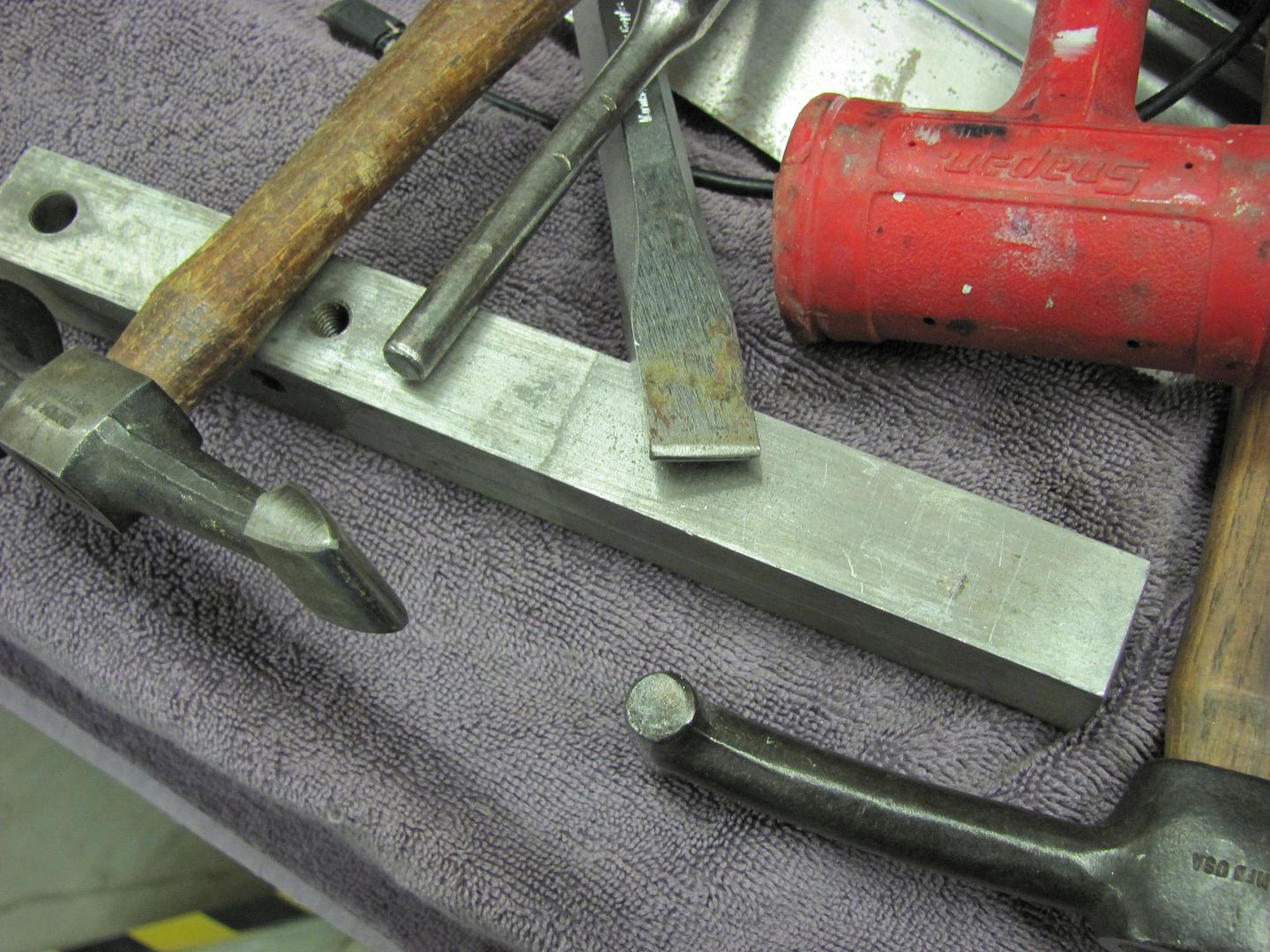
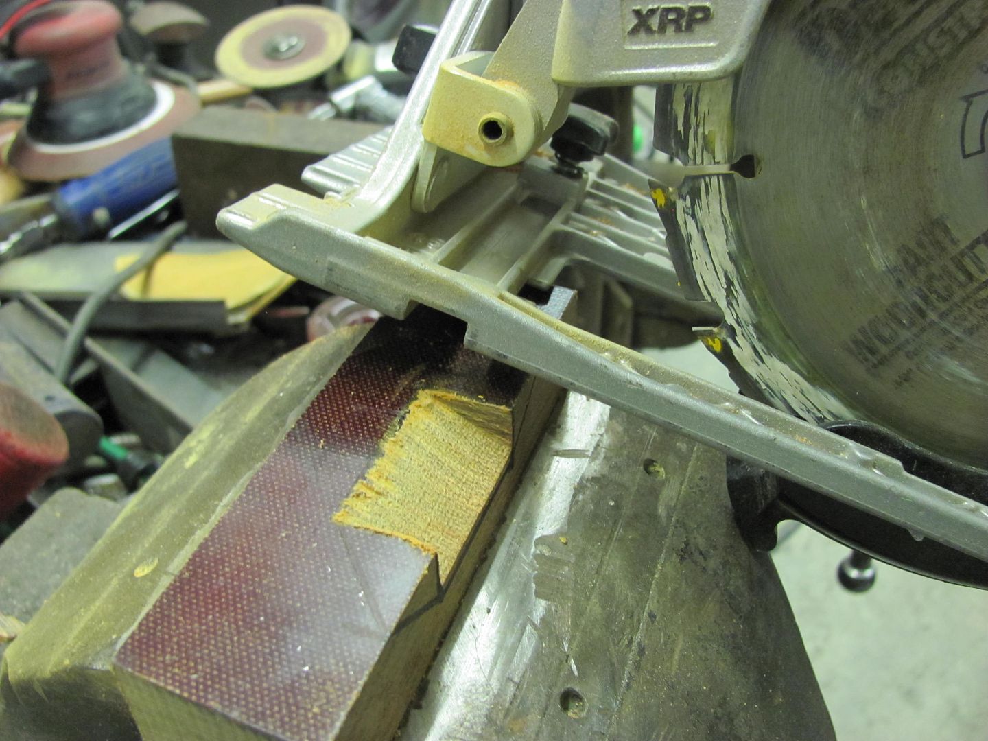
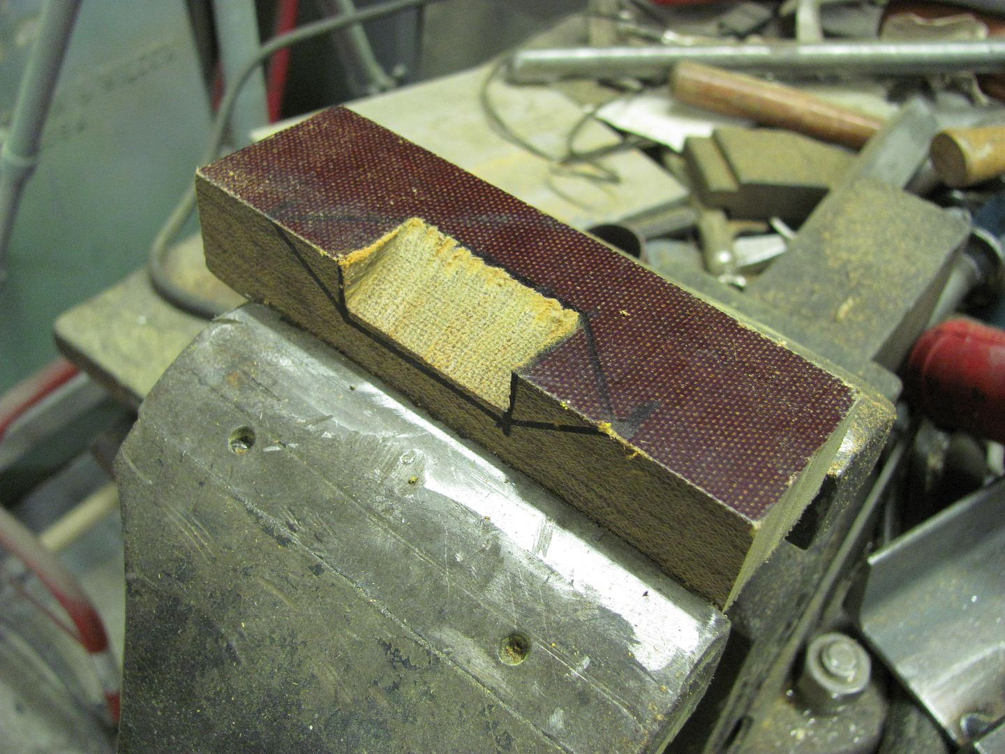
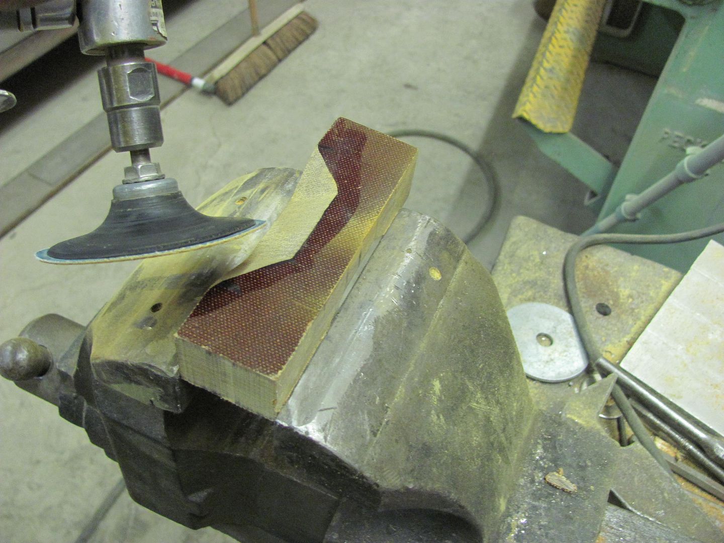
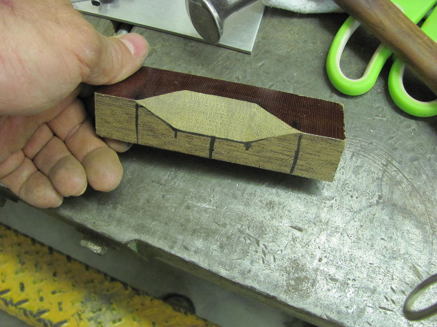
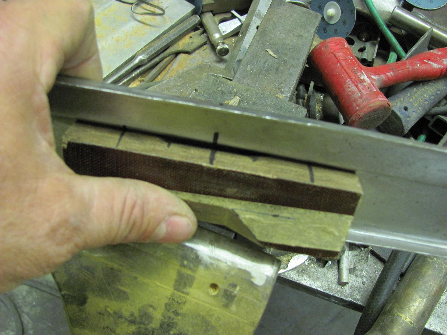
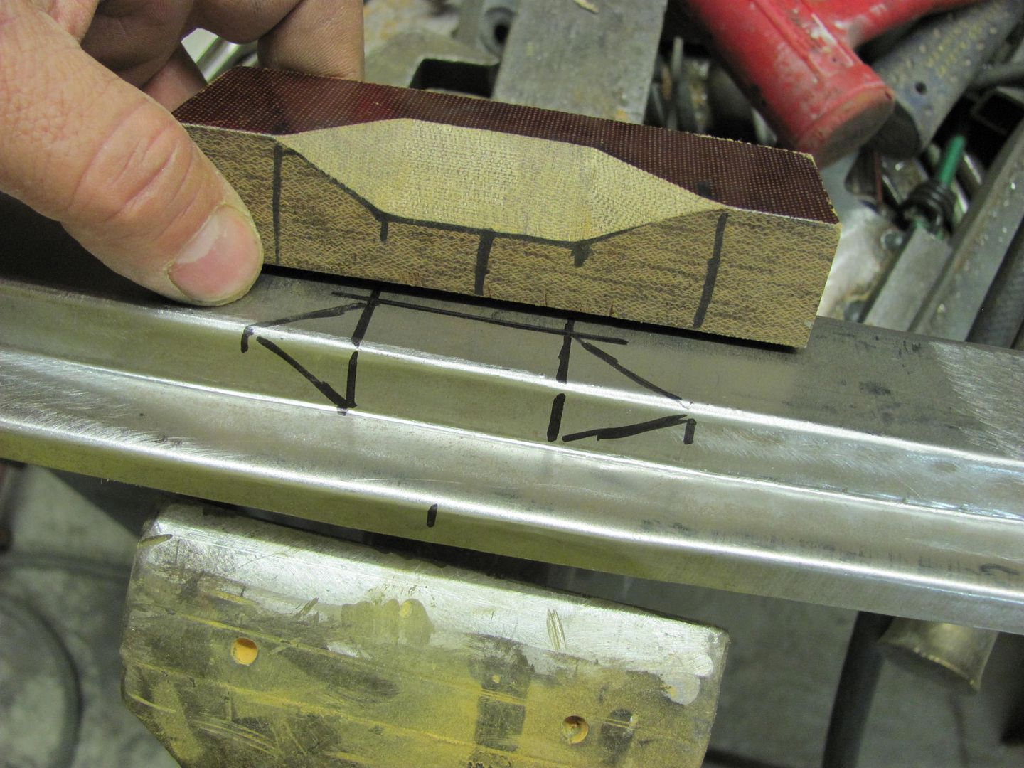
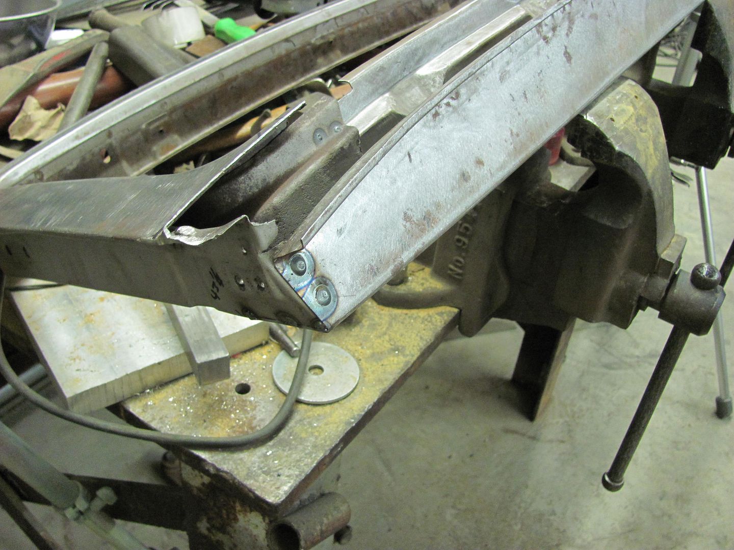
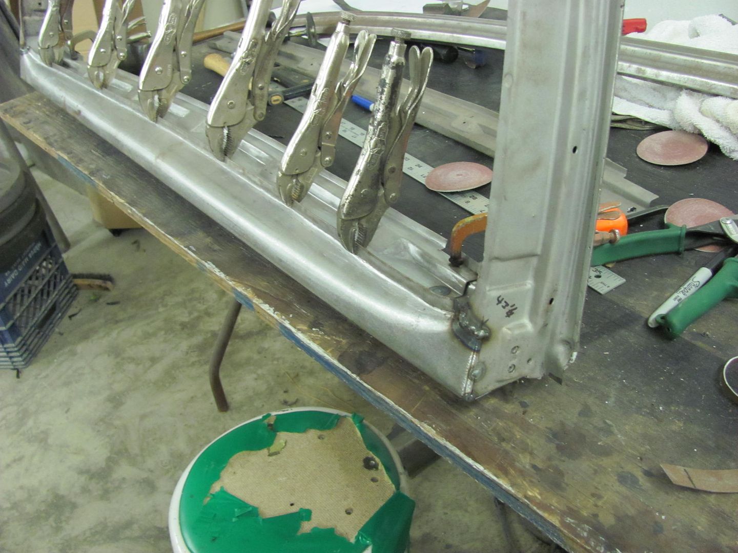
Making good tooling usually speeds up the actual job plus it improves the accuracy if you have to repeat it several times like you have on this job. I think the time spent is well worth it.


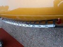
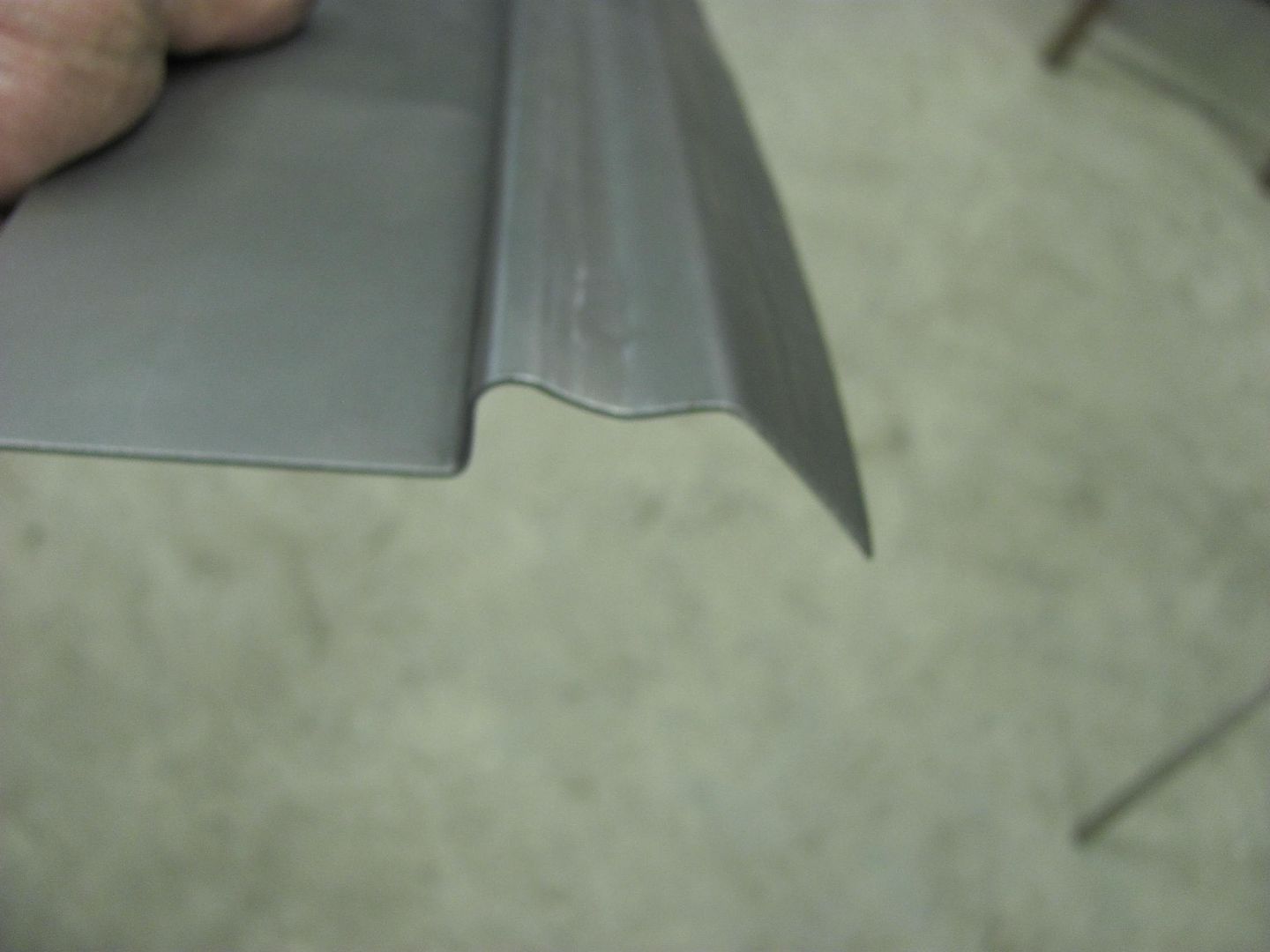
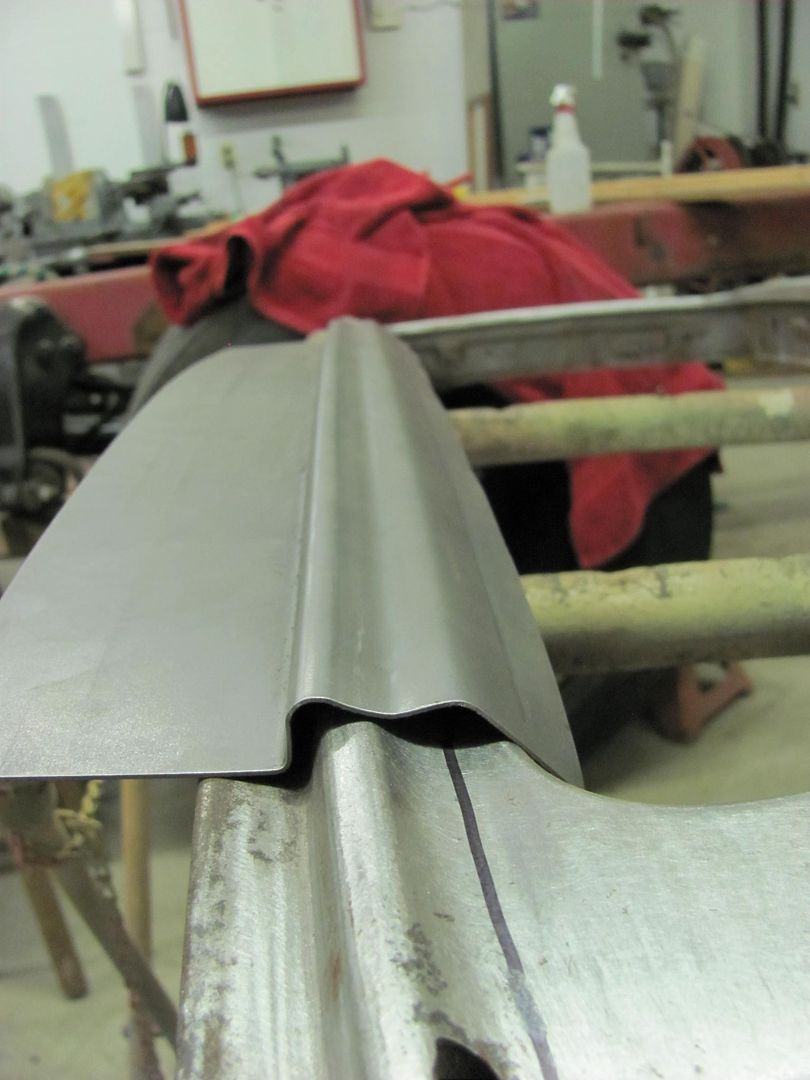
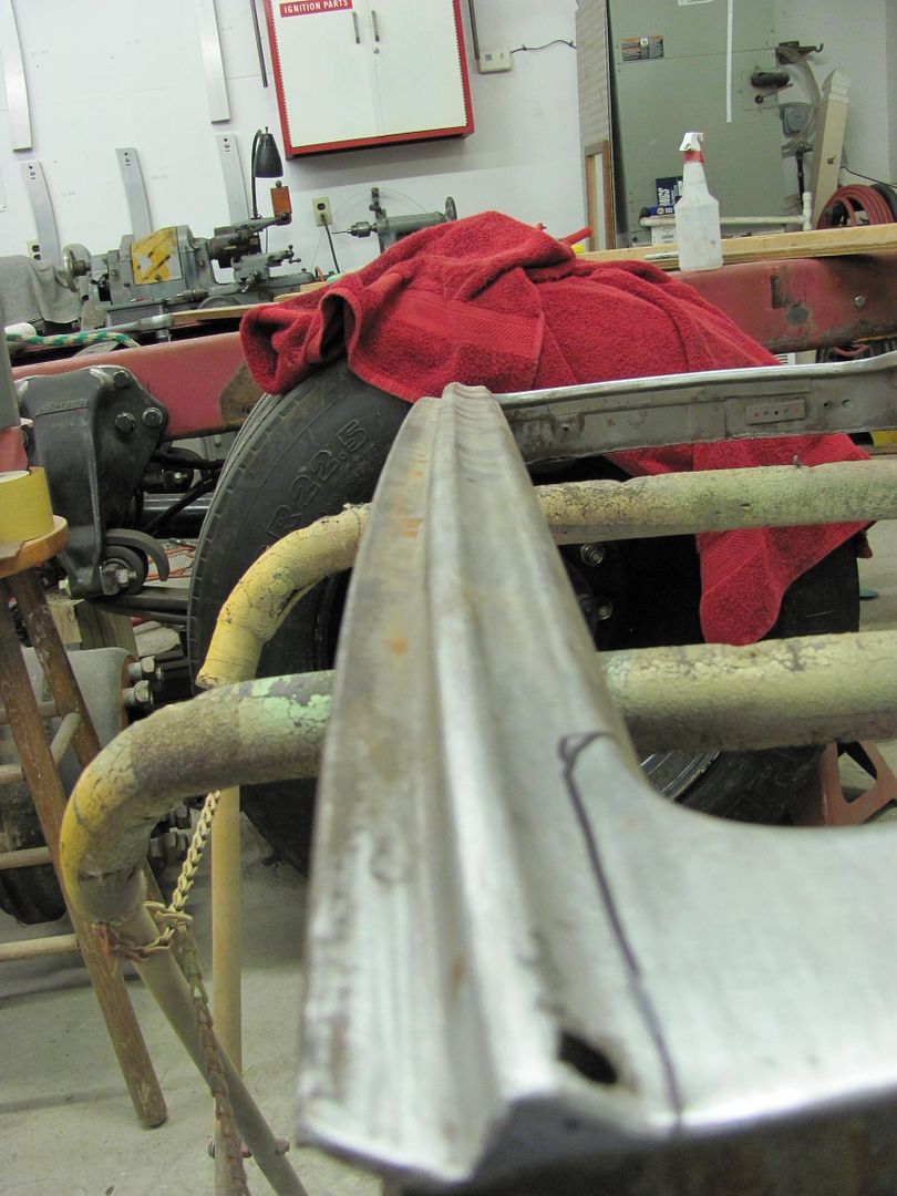
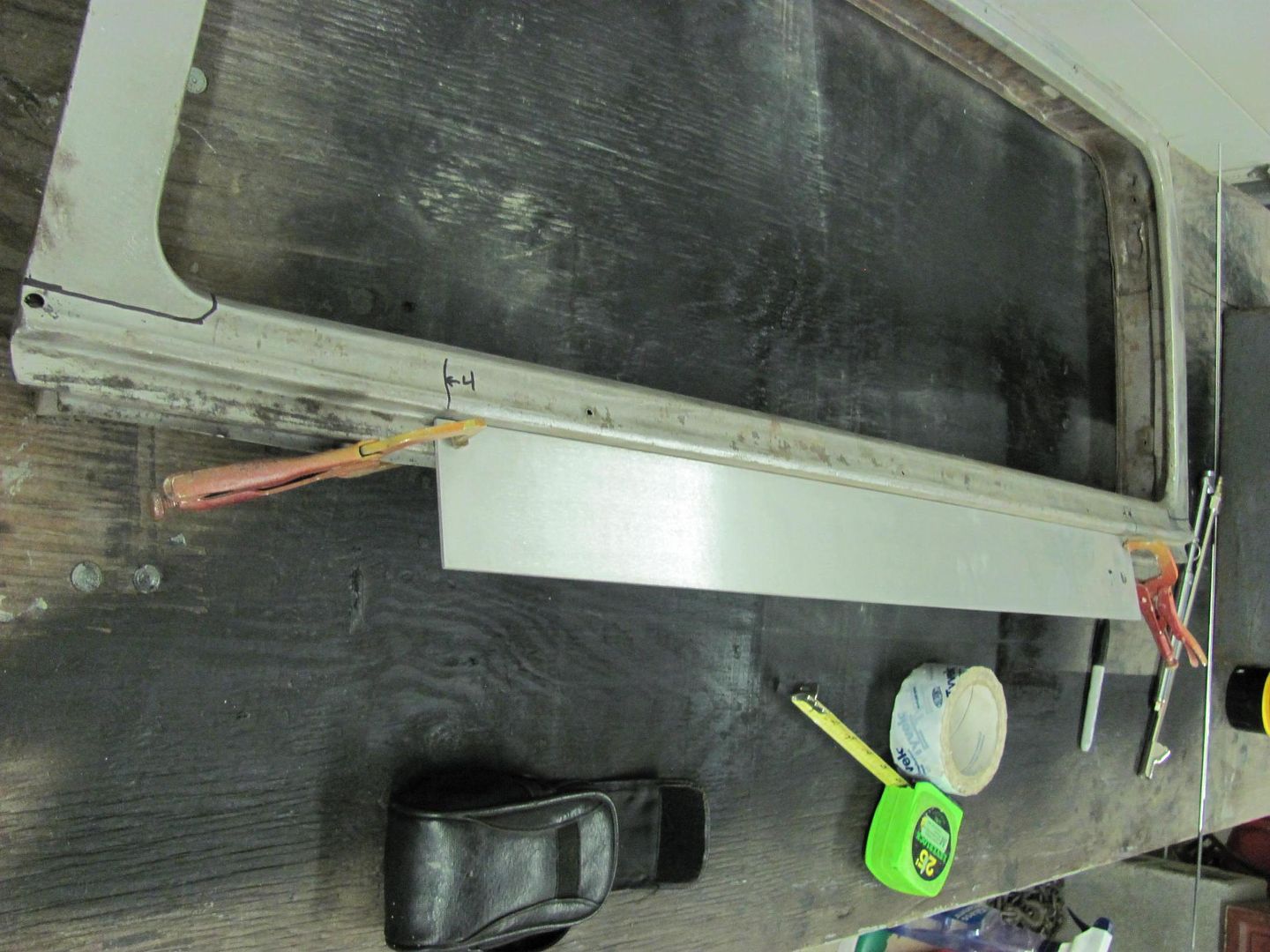
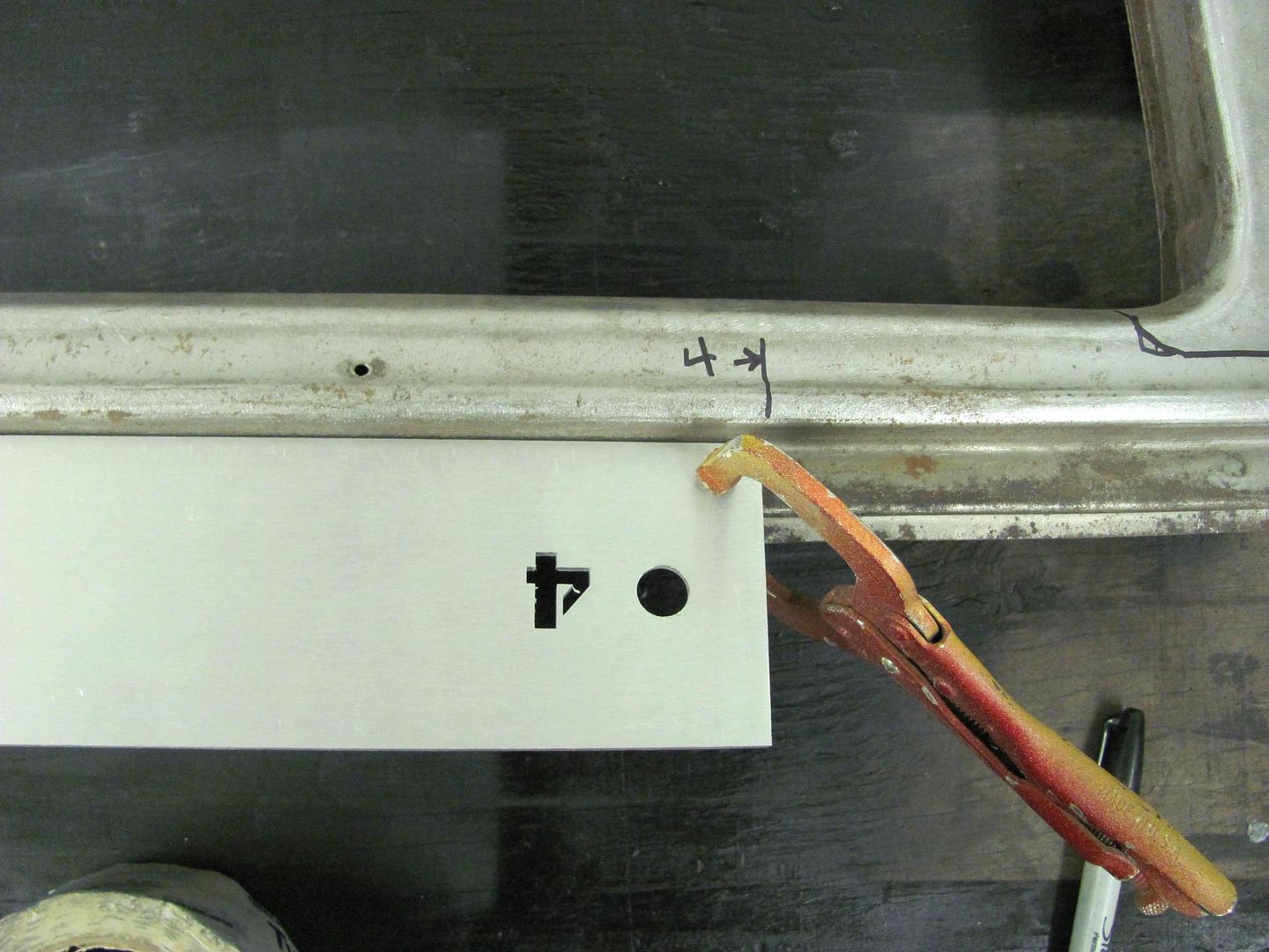
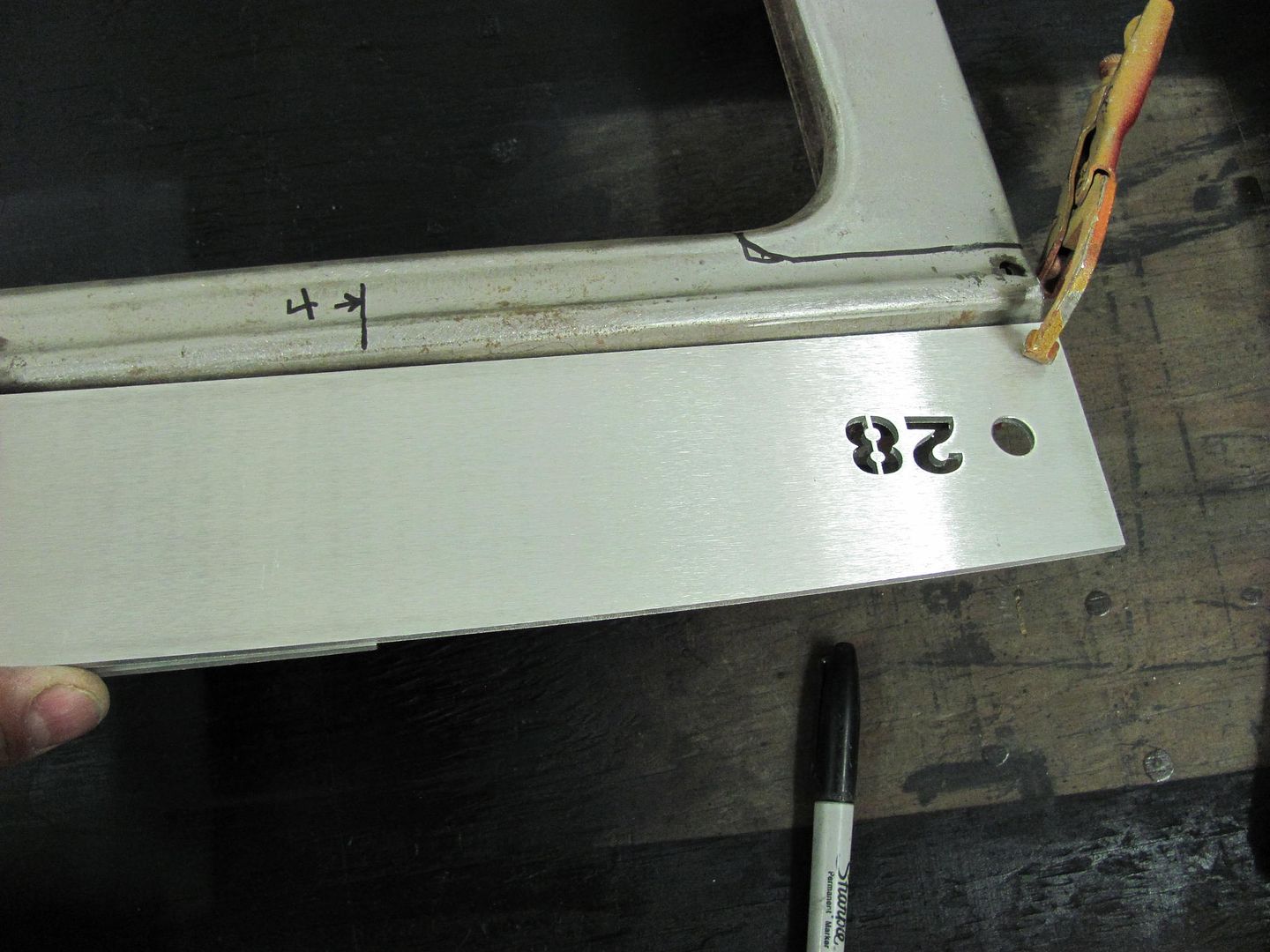
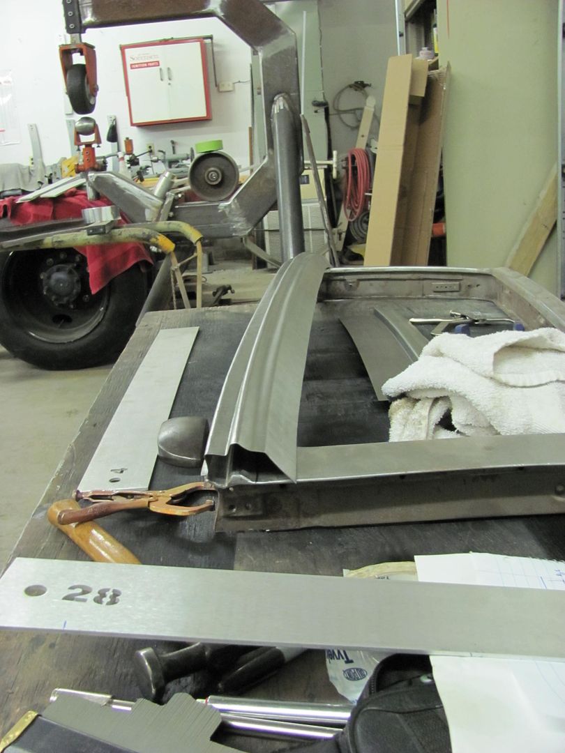
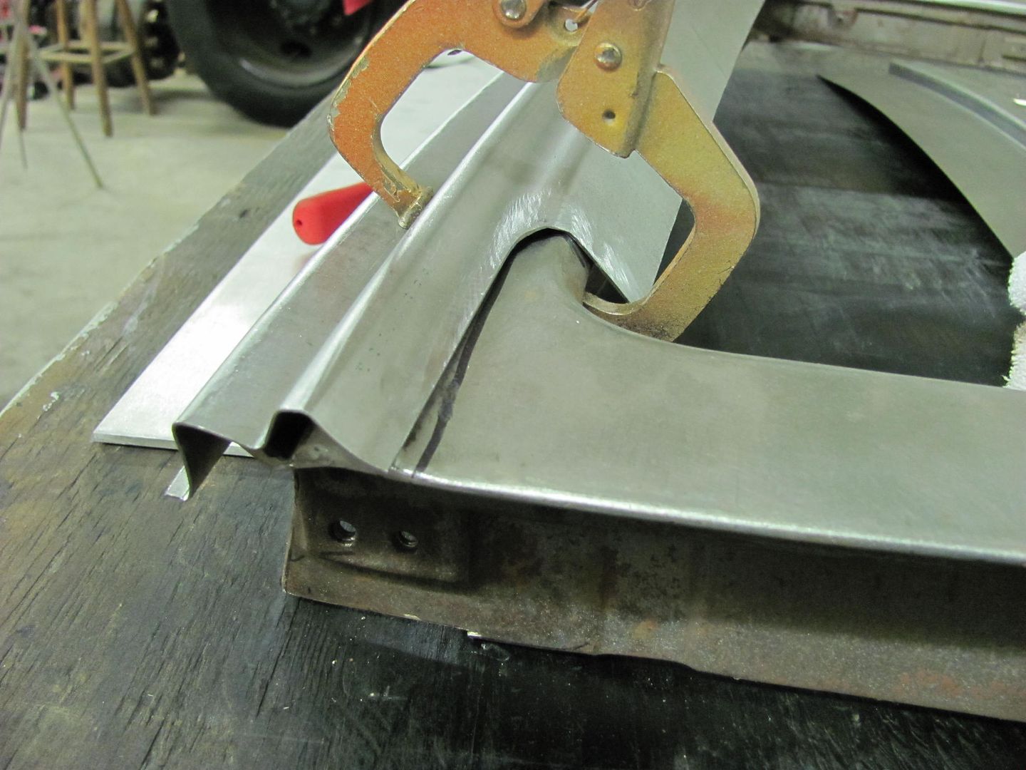
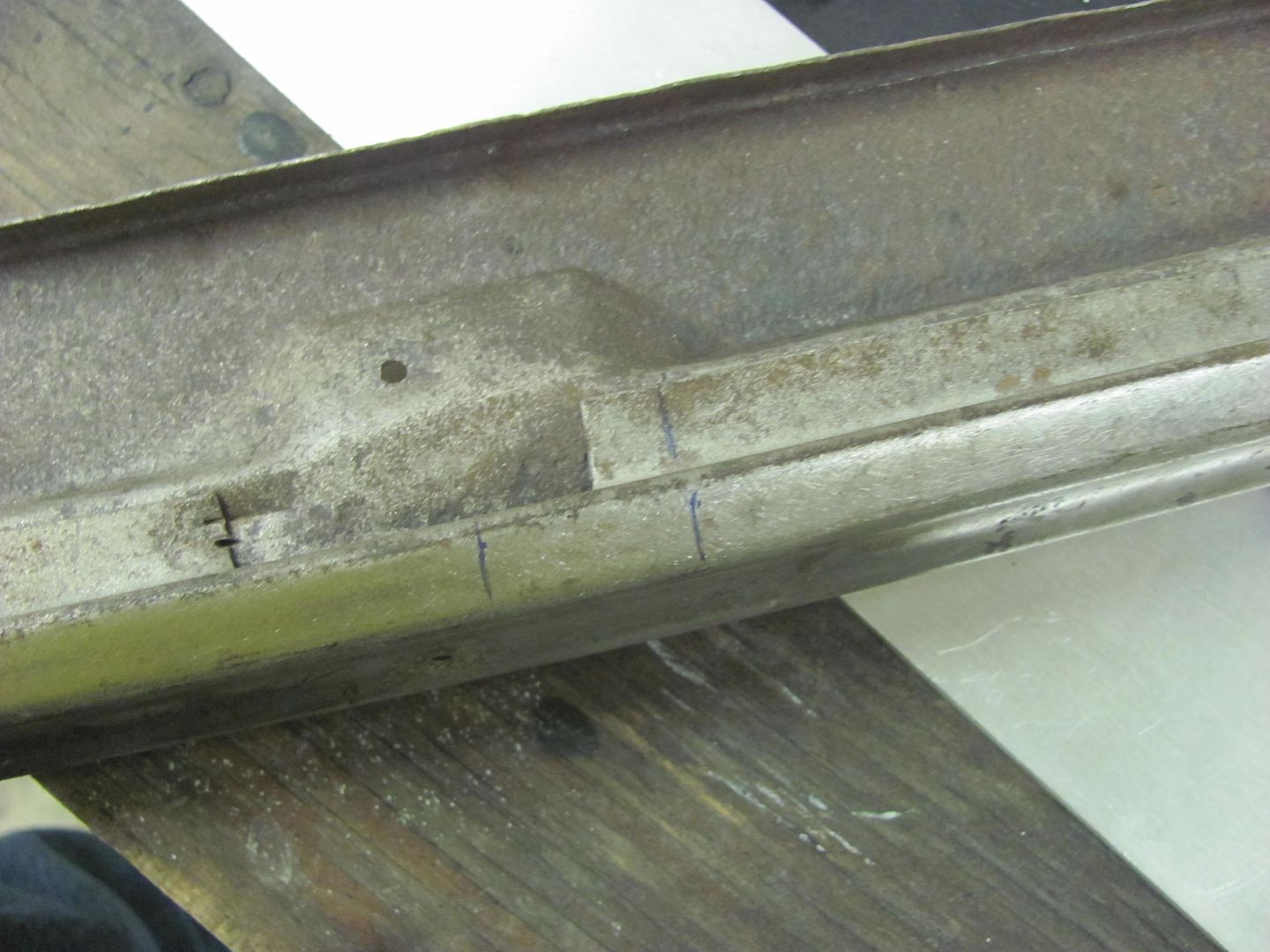
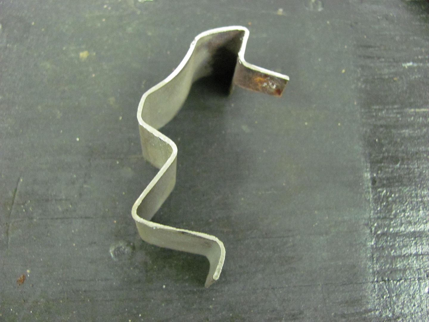
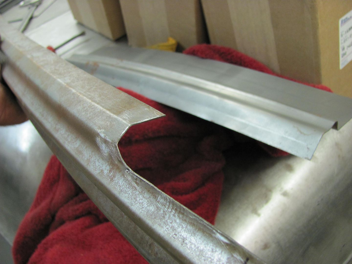
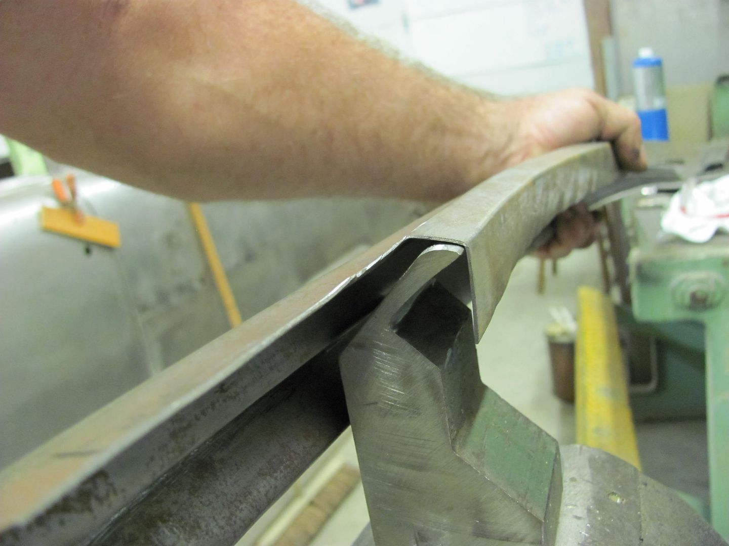
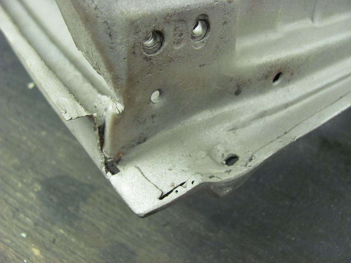
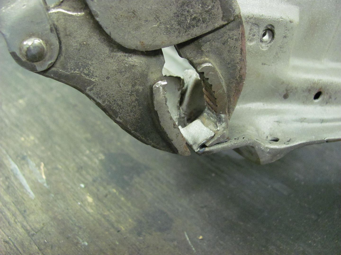
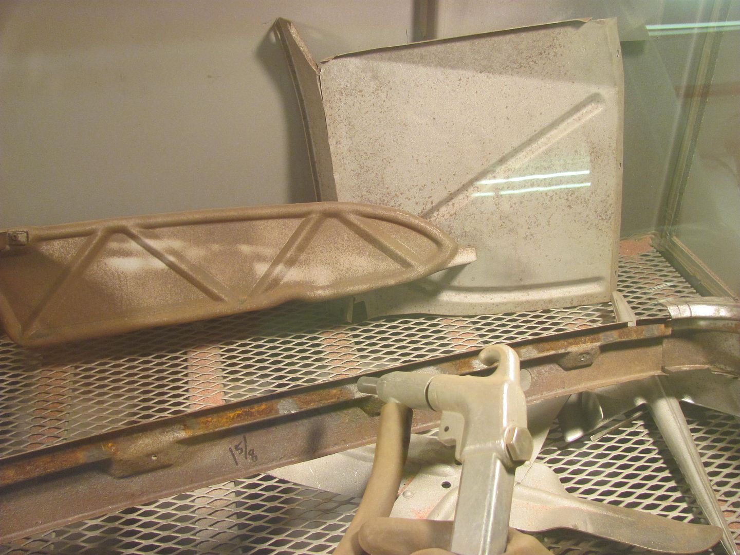
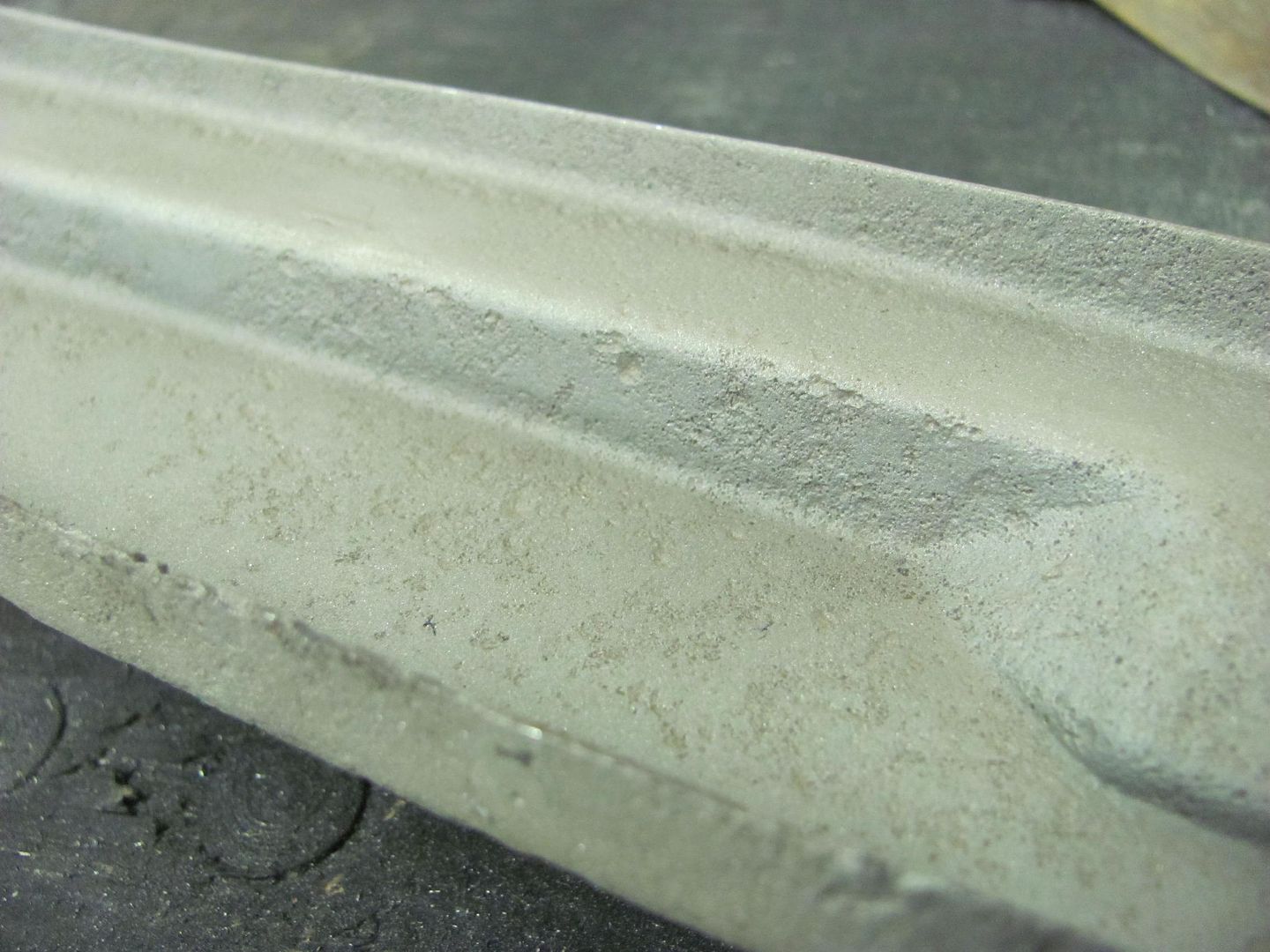
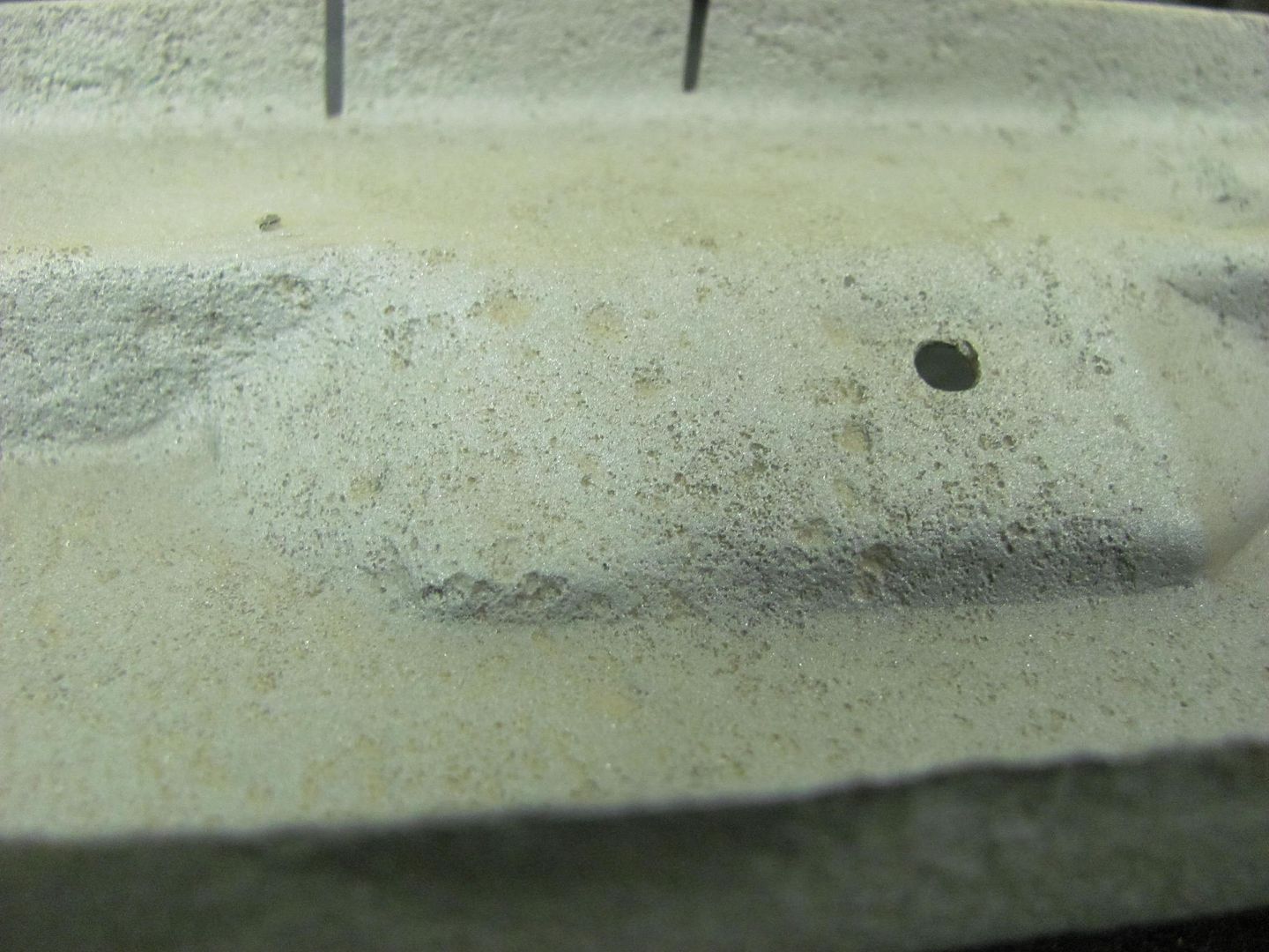
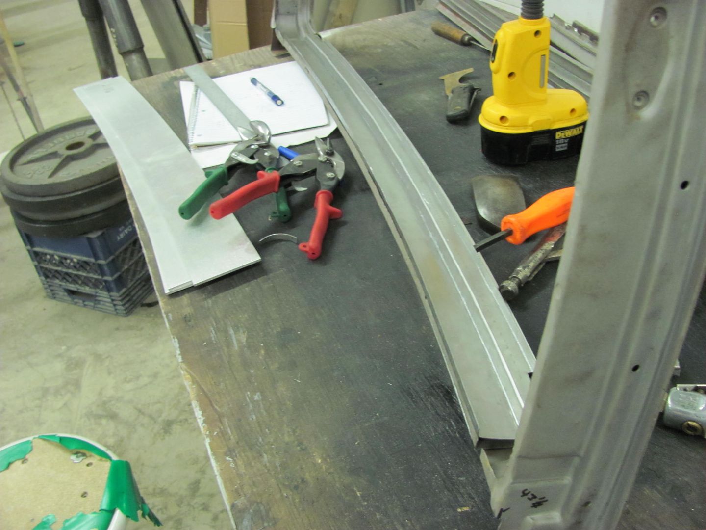
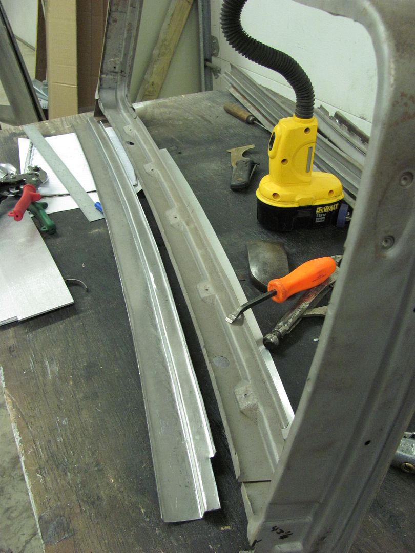
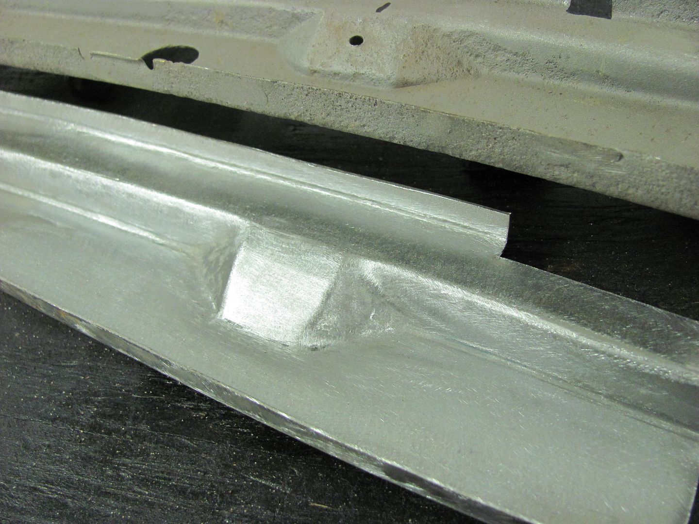
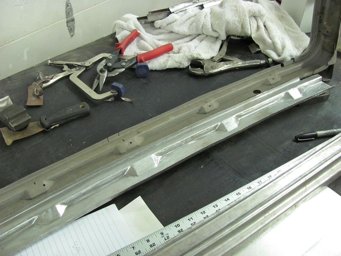
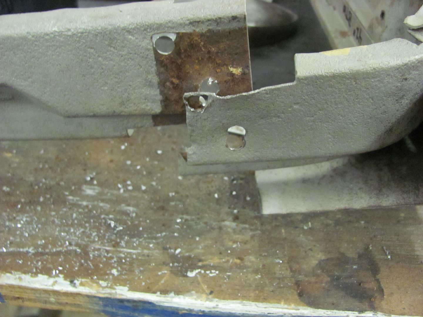
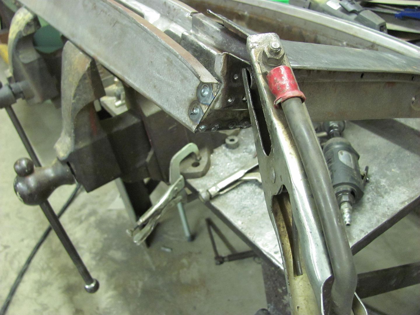
In order to help spread the load and provide support, used a piece of 16 ga stainless to fab up this piece to go on the bottom of that corner of the door. The inside was media blasted so some construction adhesive might hold, as was the outside for paint adhesion. I used stainless as regular cold rolled steel and latex paint will no doubt cause some rusting in the nice white paint... Here's the fix:


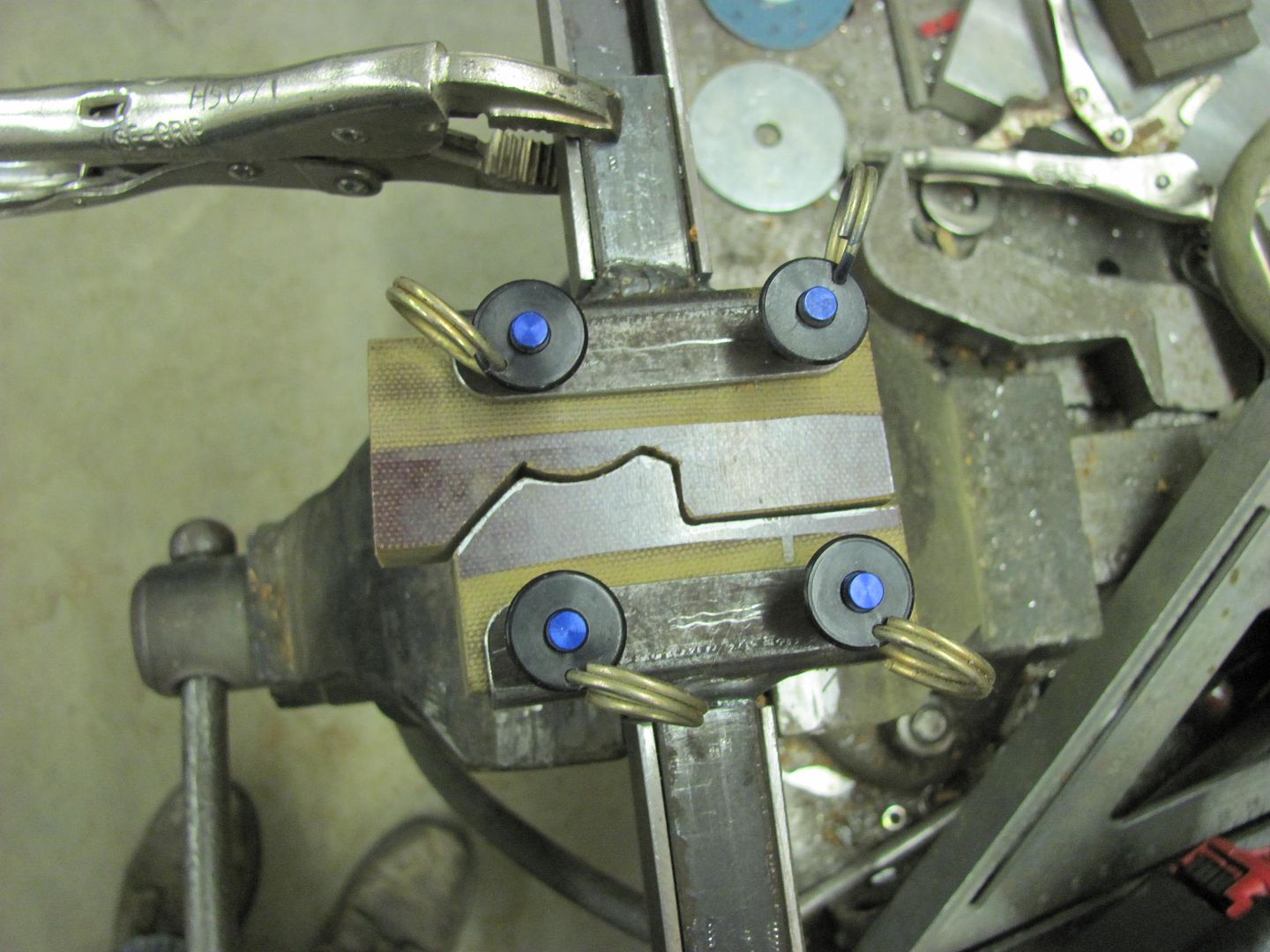
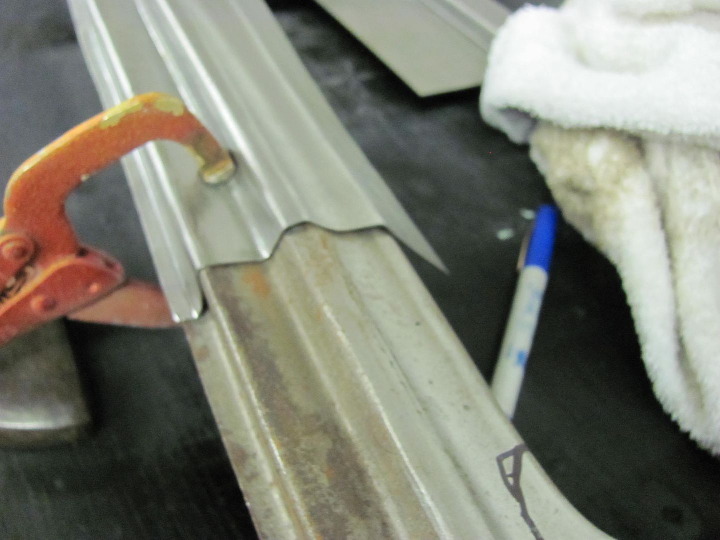
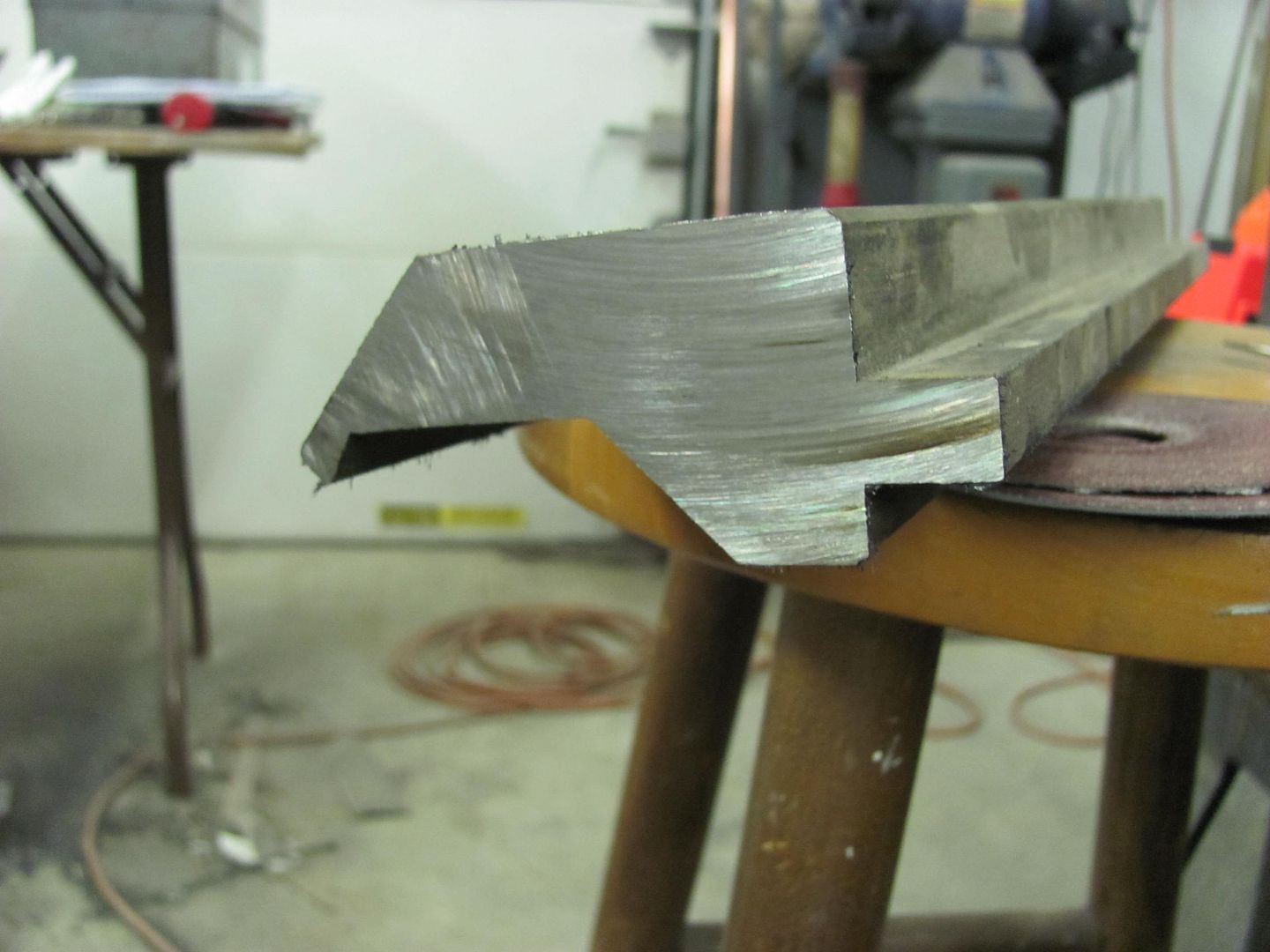
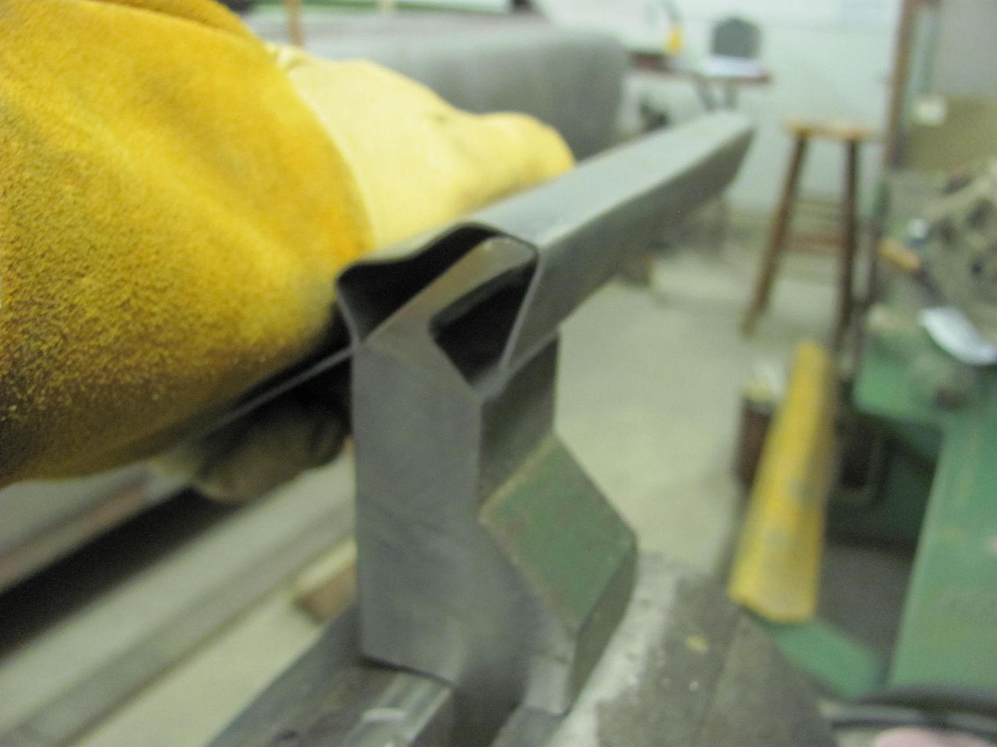
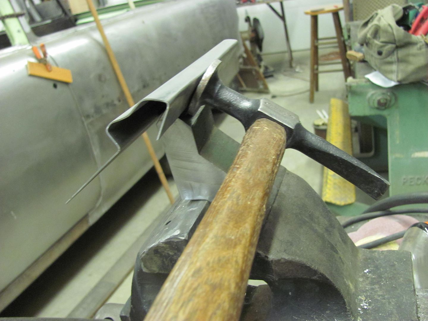
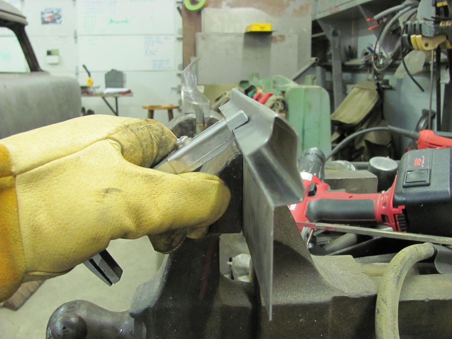
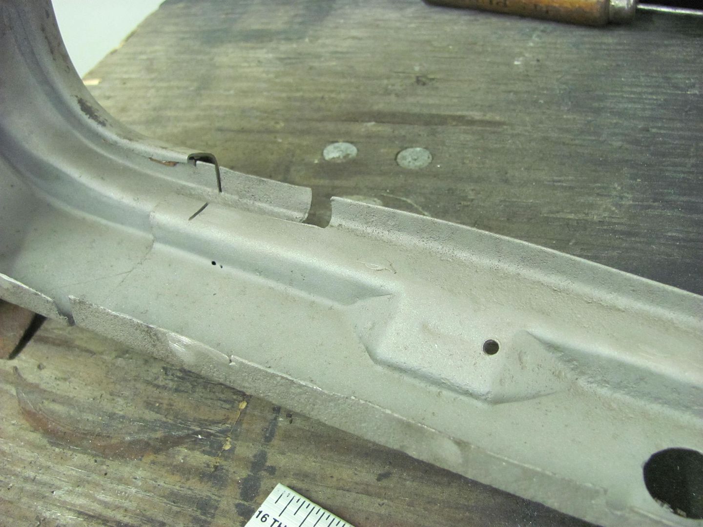
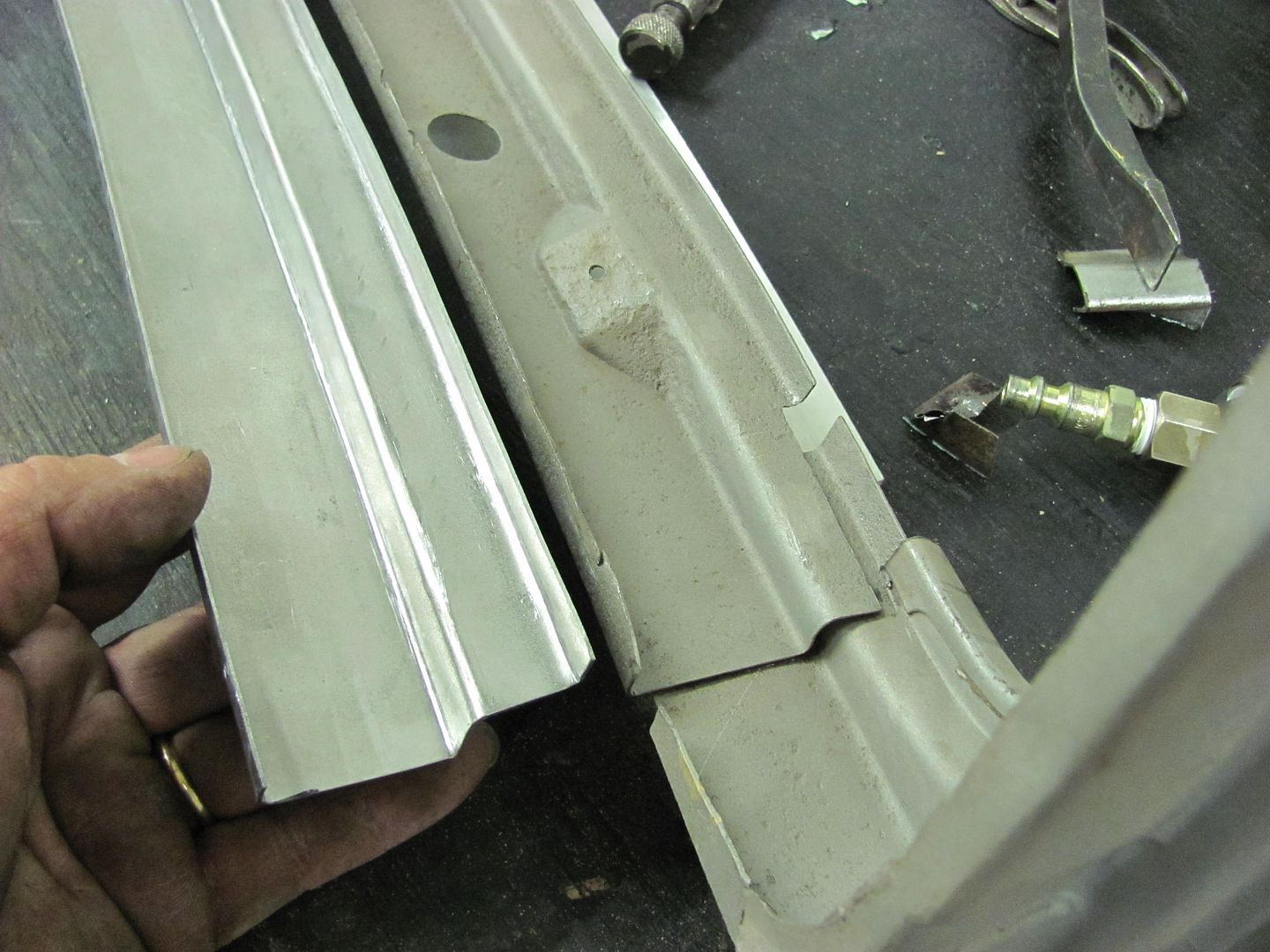
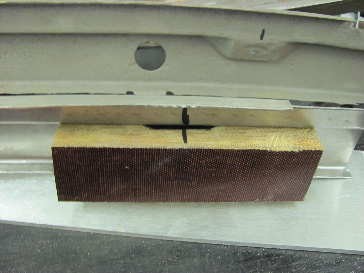
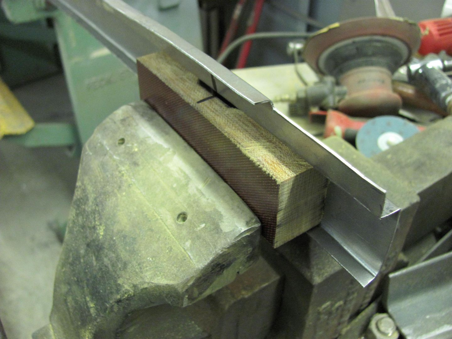
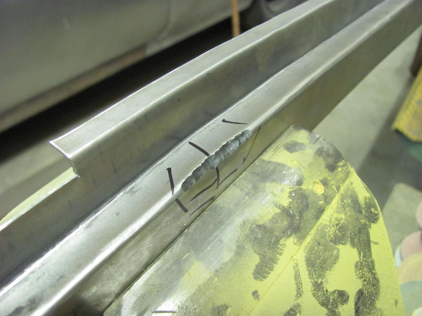
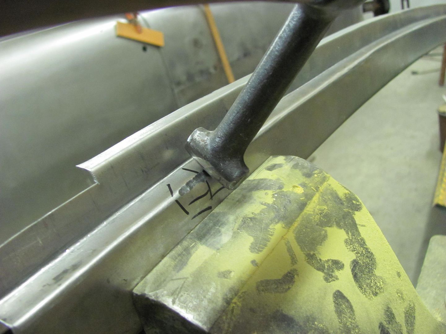
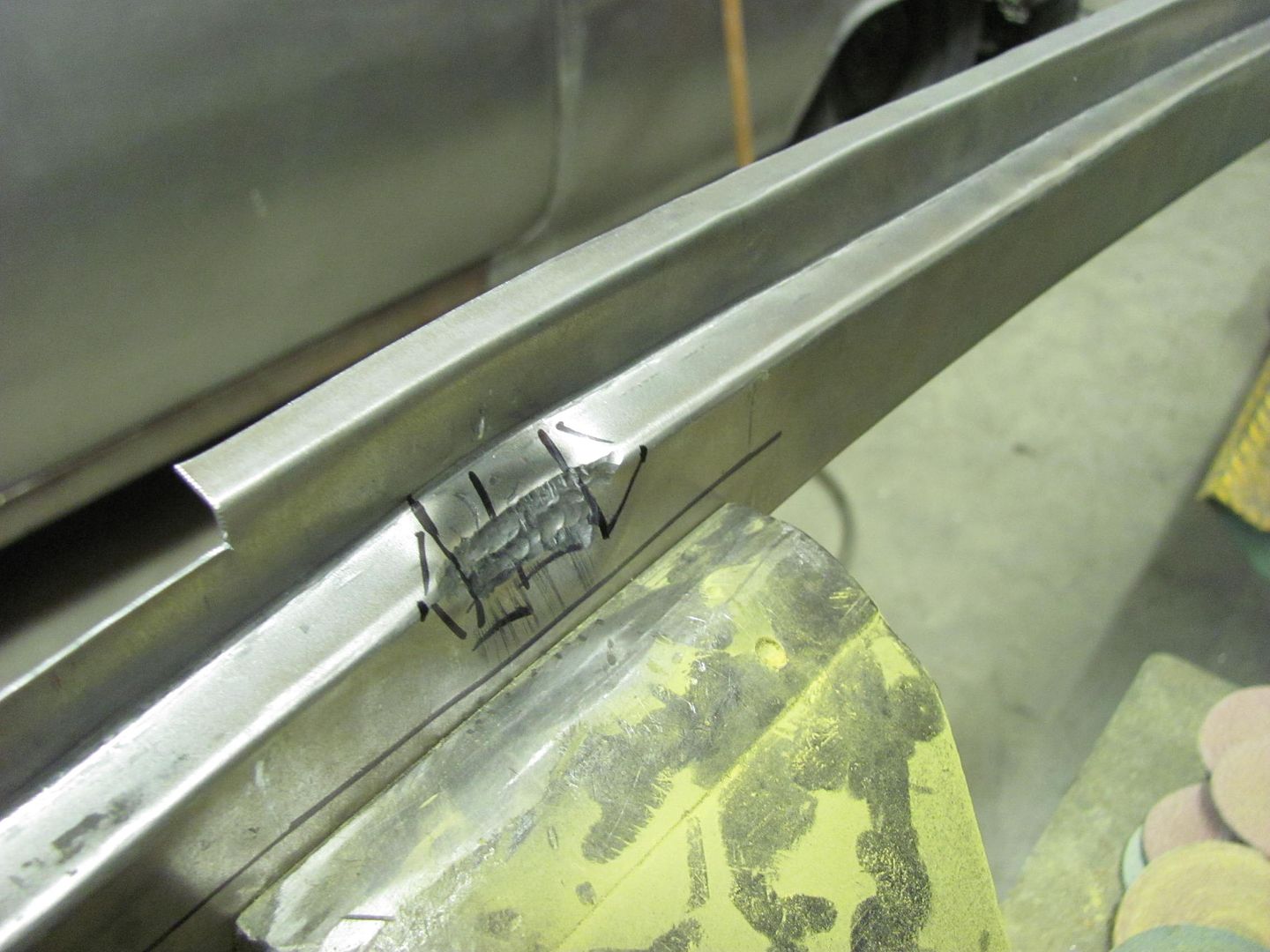
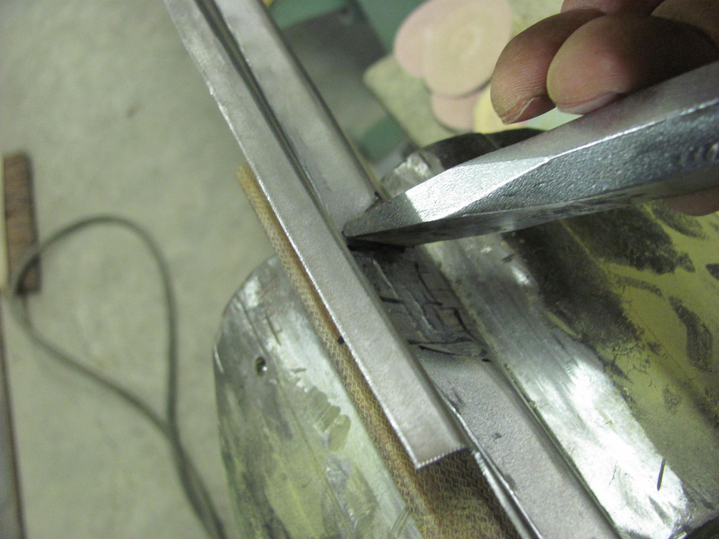
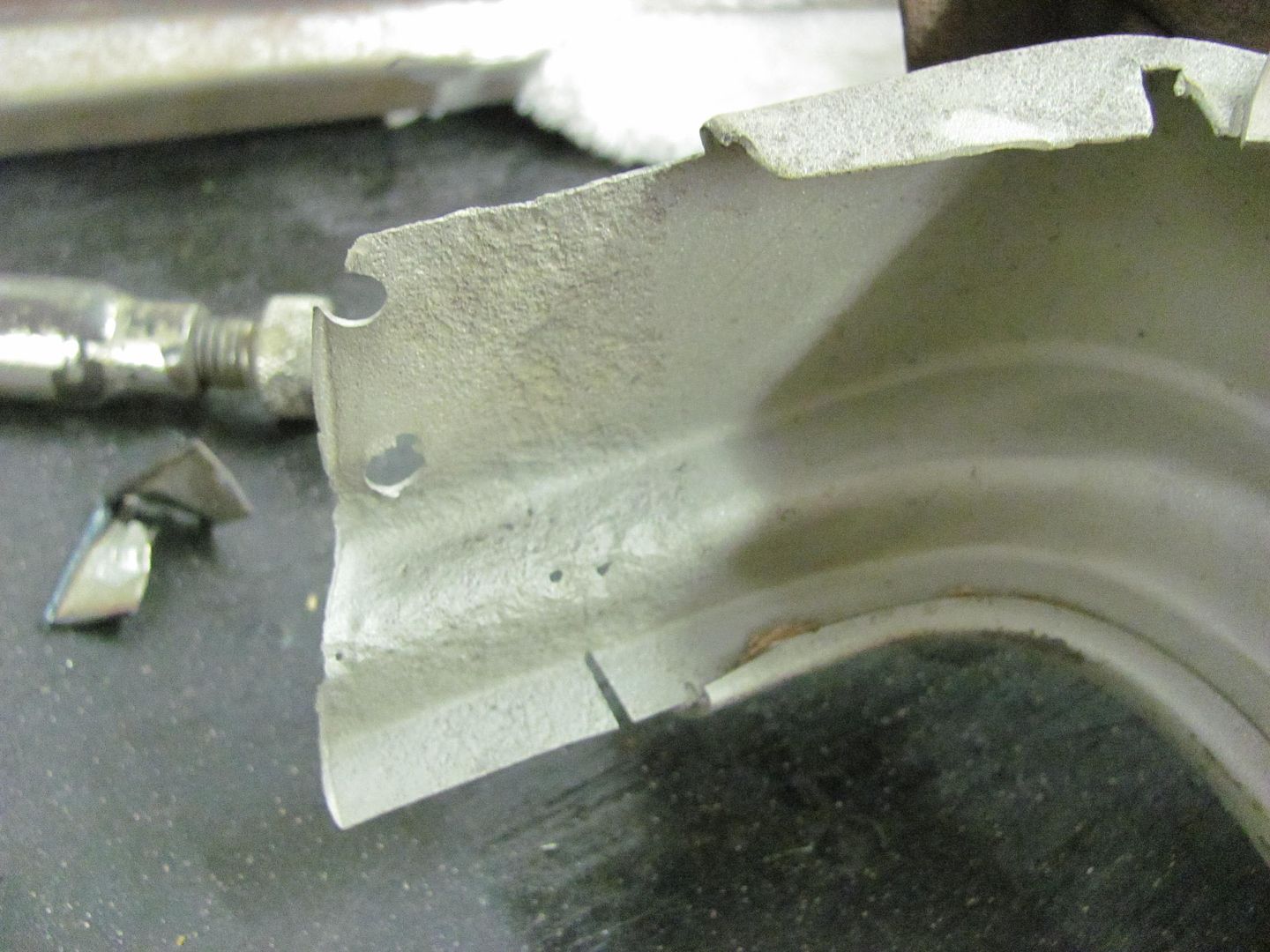
Kevin, forcing the metal into the phenolic anvil did create a bit of distortion around that detail, but a hammer and flat anvil cleaned it up nicely. I think press tooling would have resulted in less of this issue, but I didn't have that capability. Have to get you on retainer.....
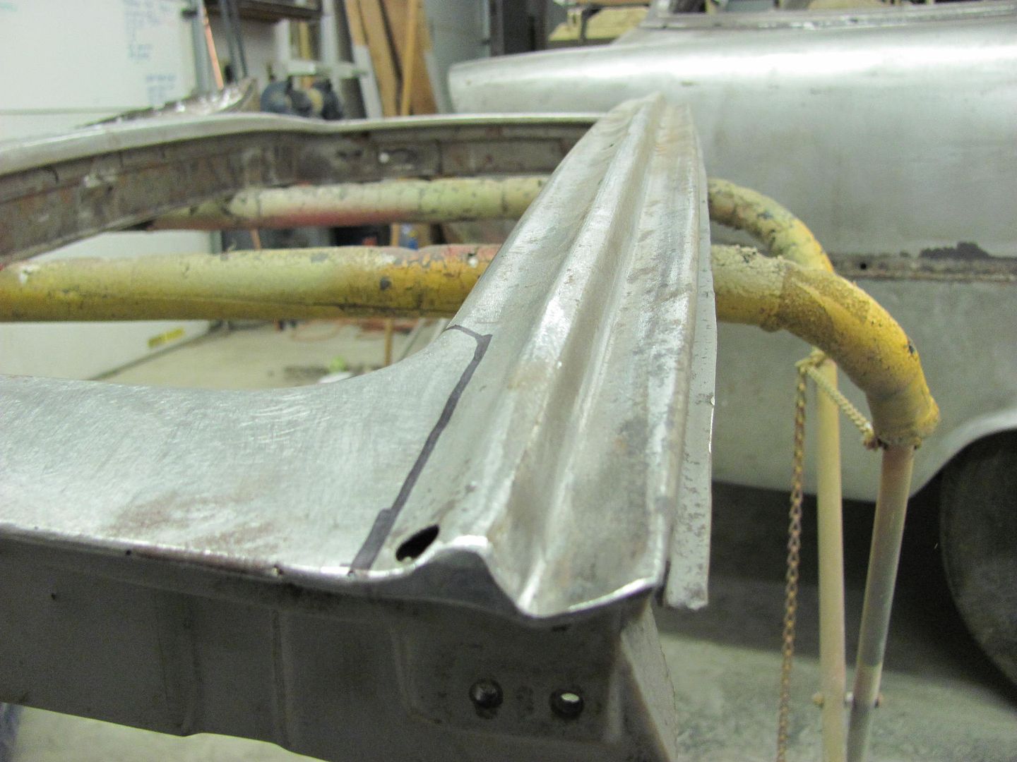
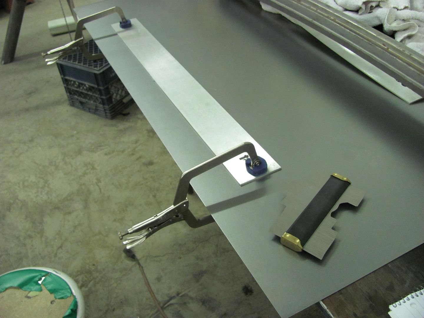
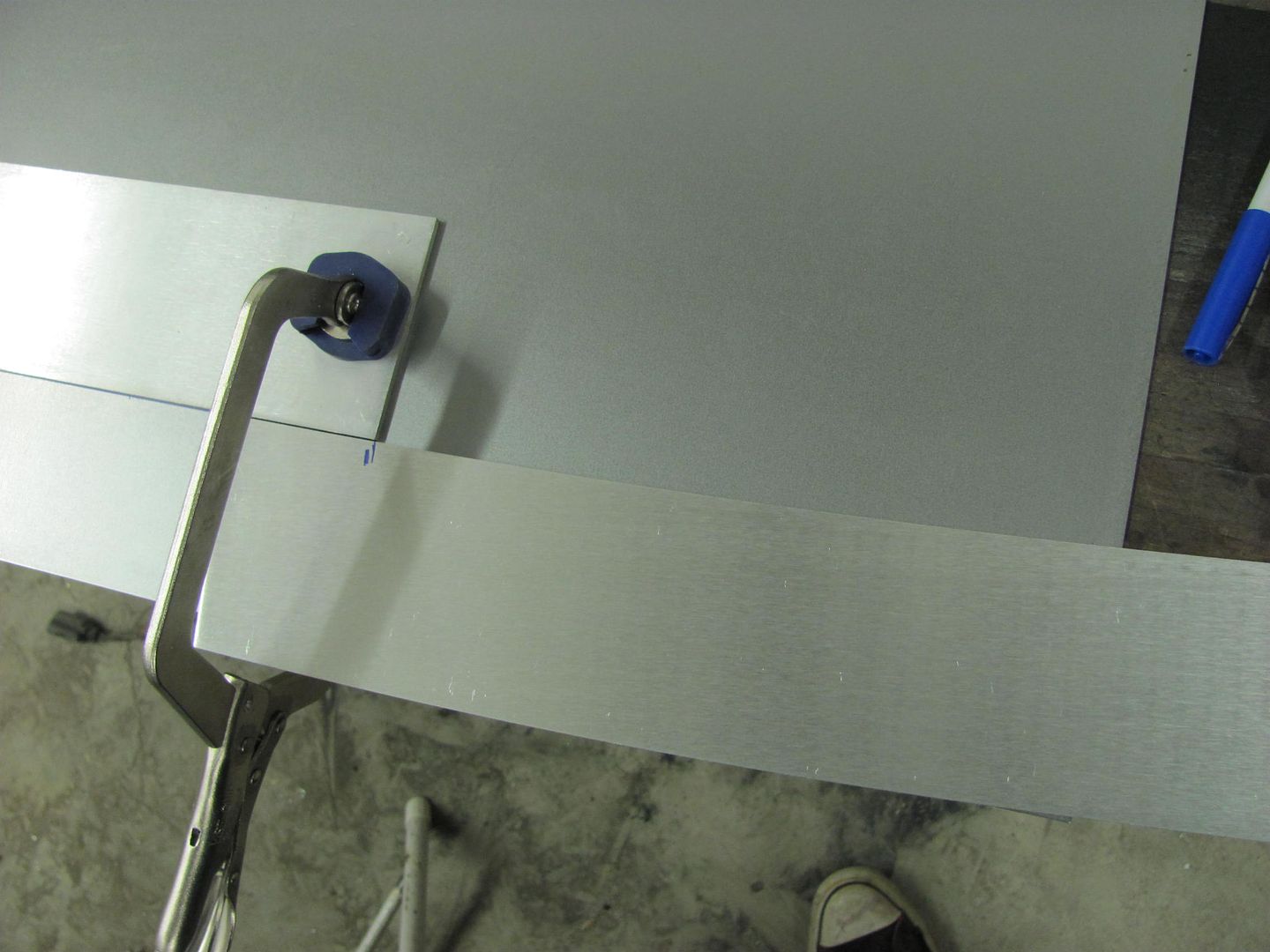
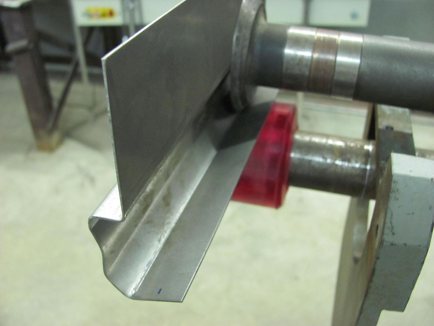
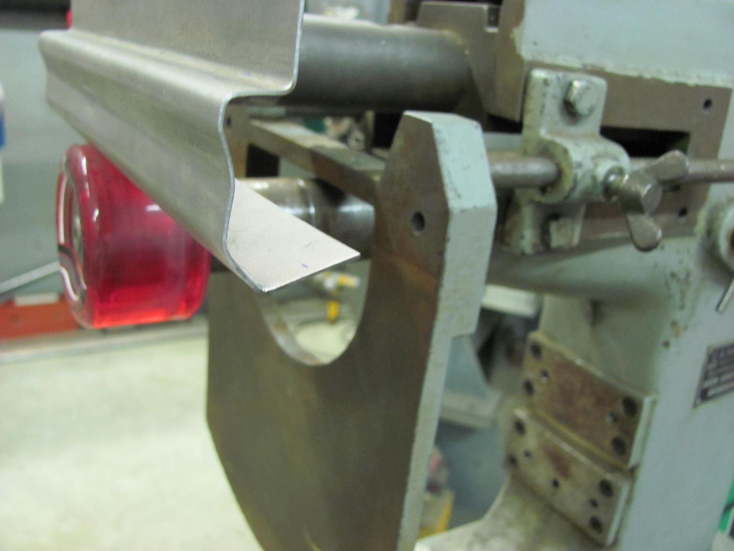
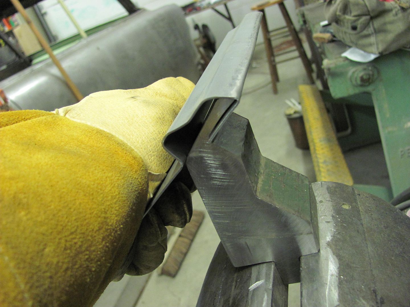
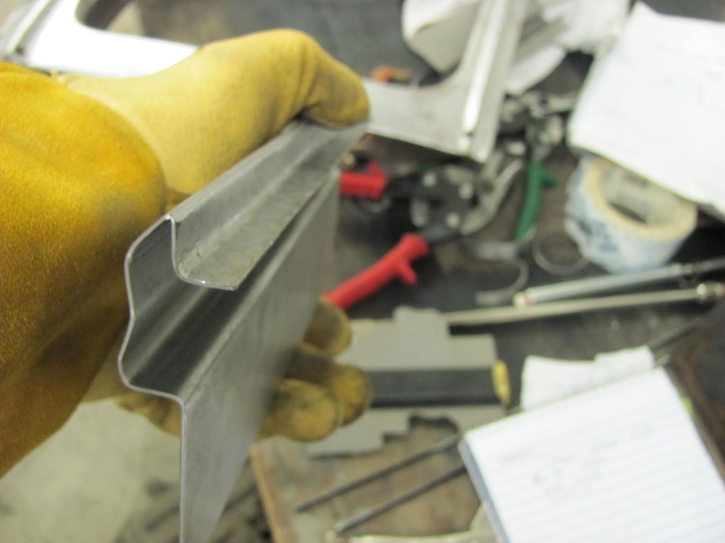
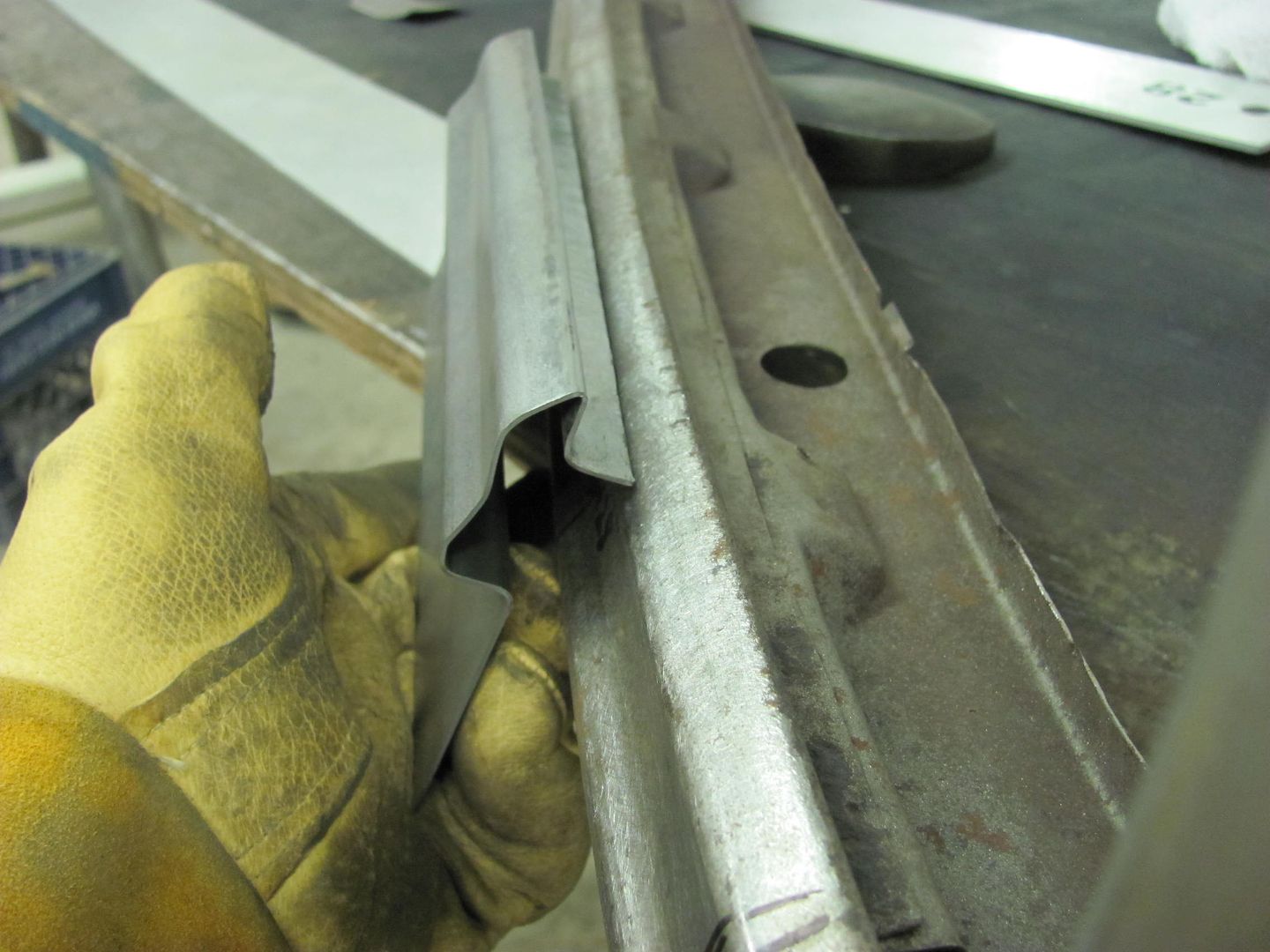
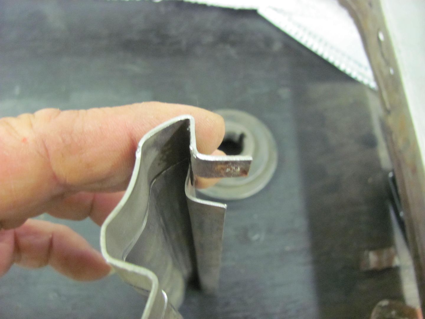
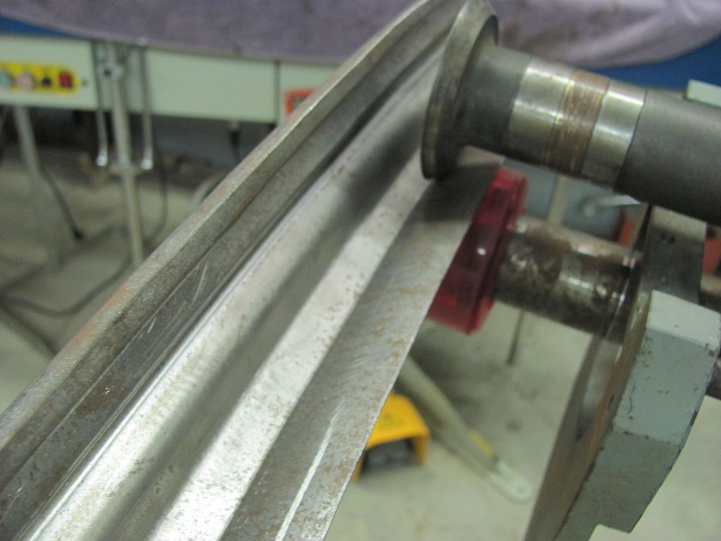
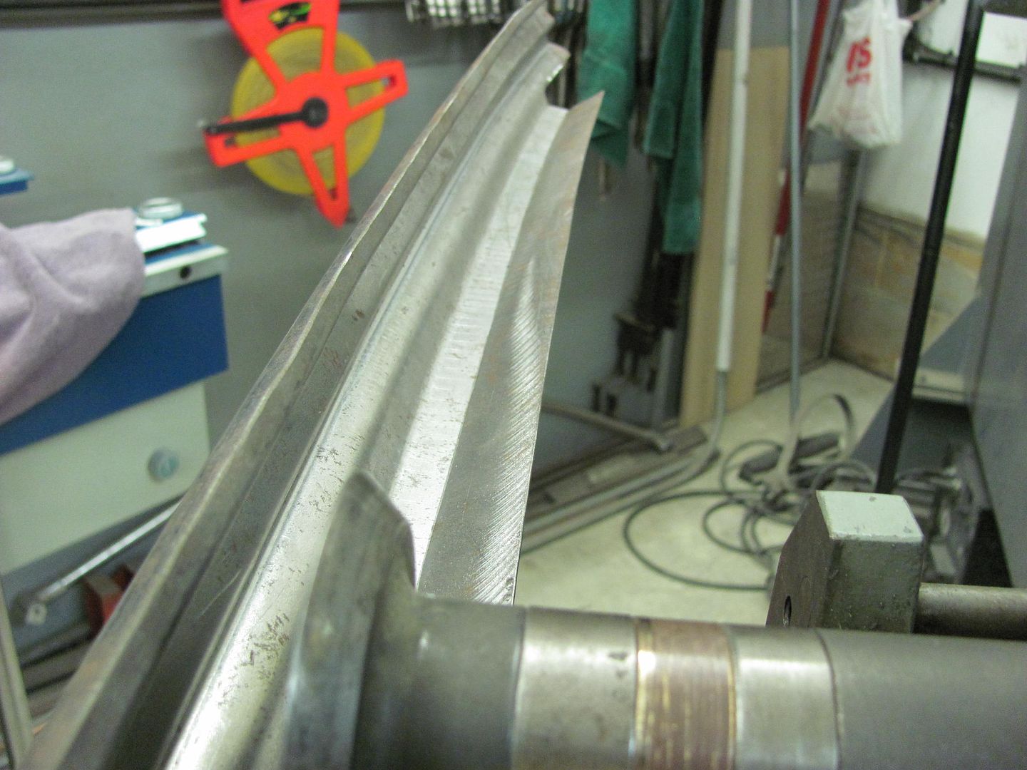
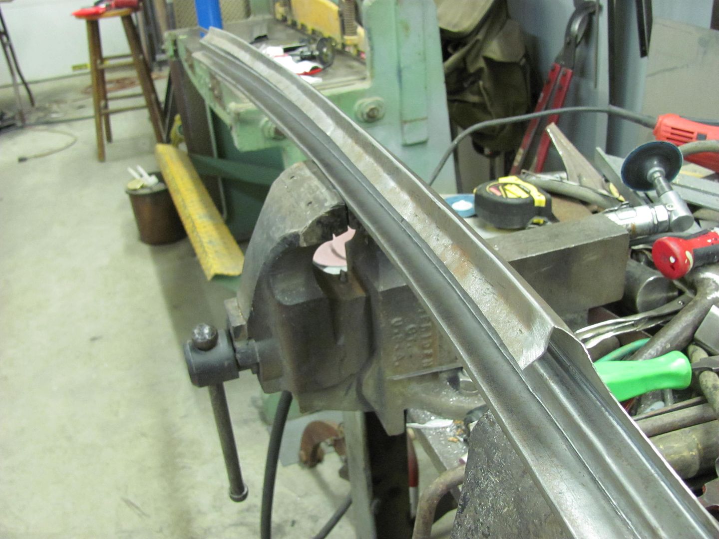
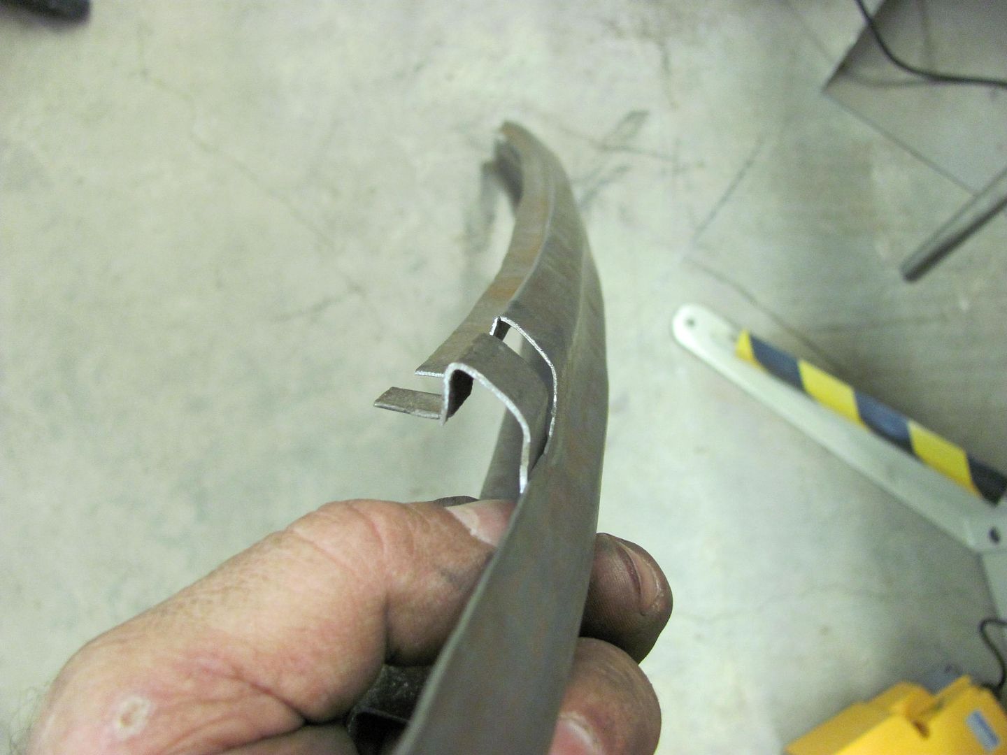
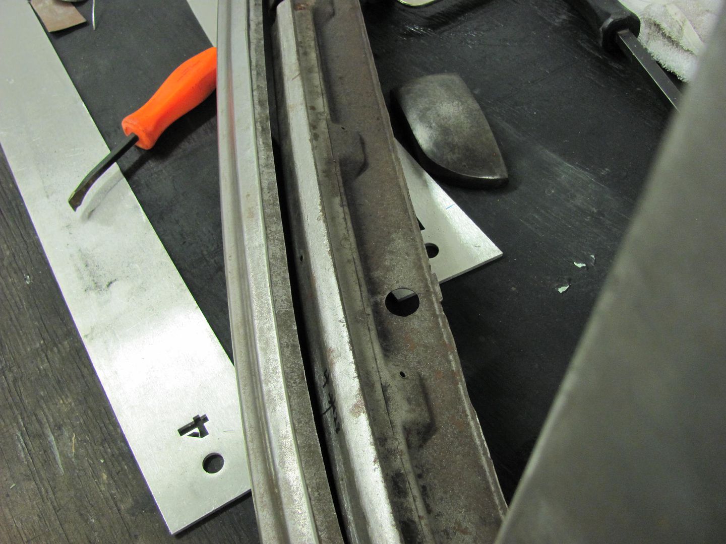
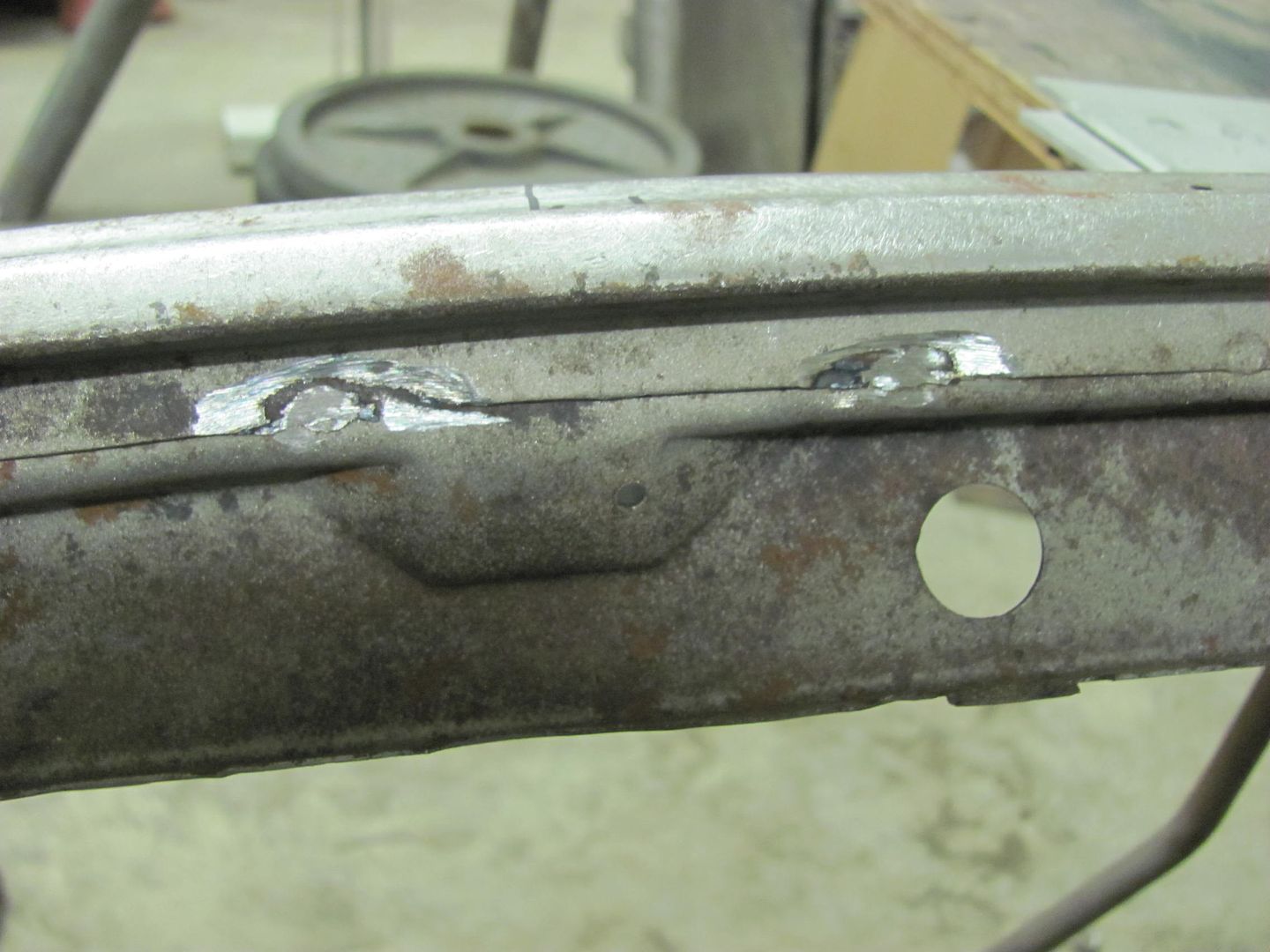
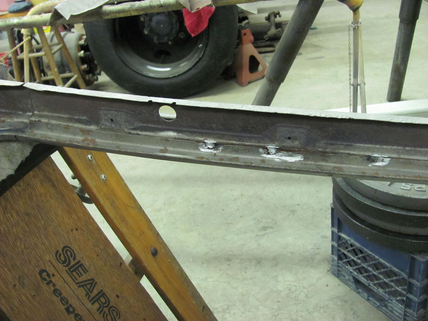
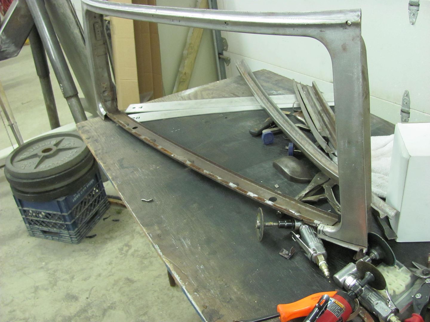
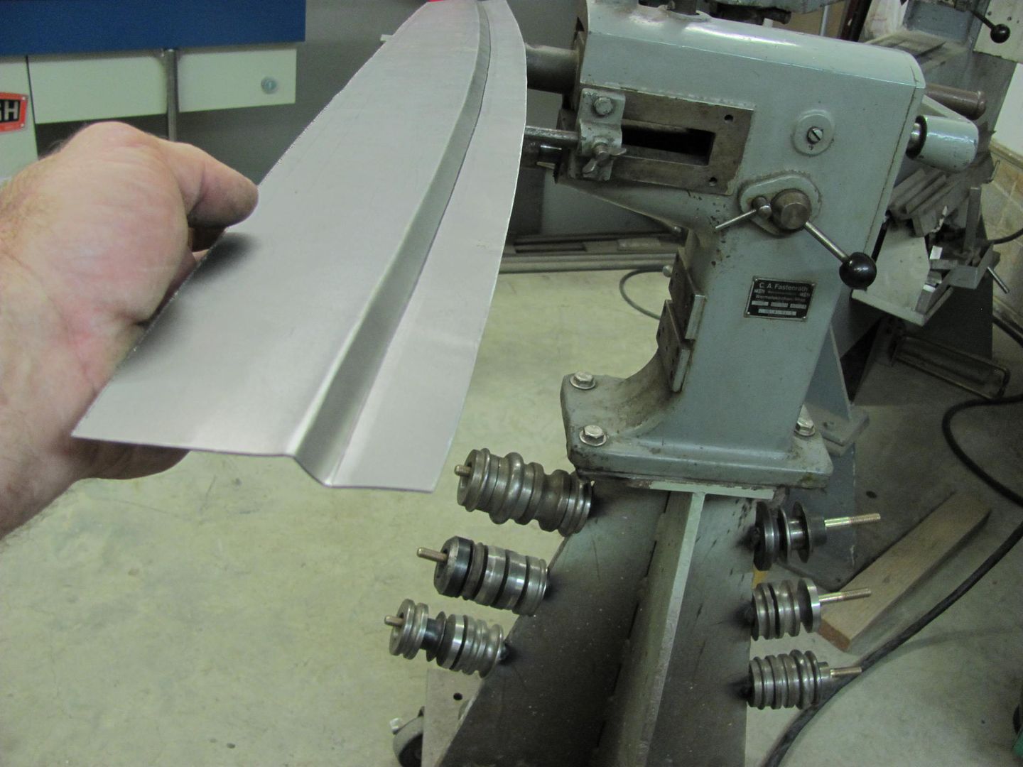
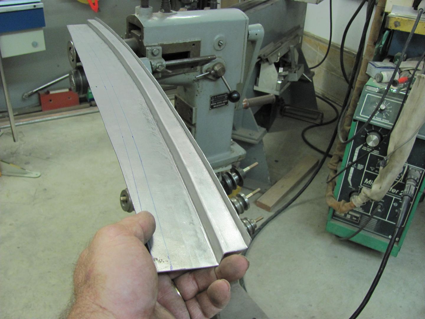
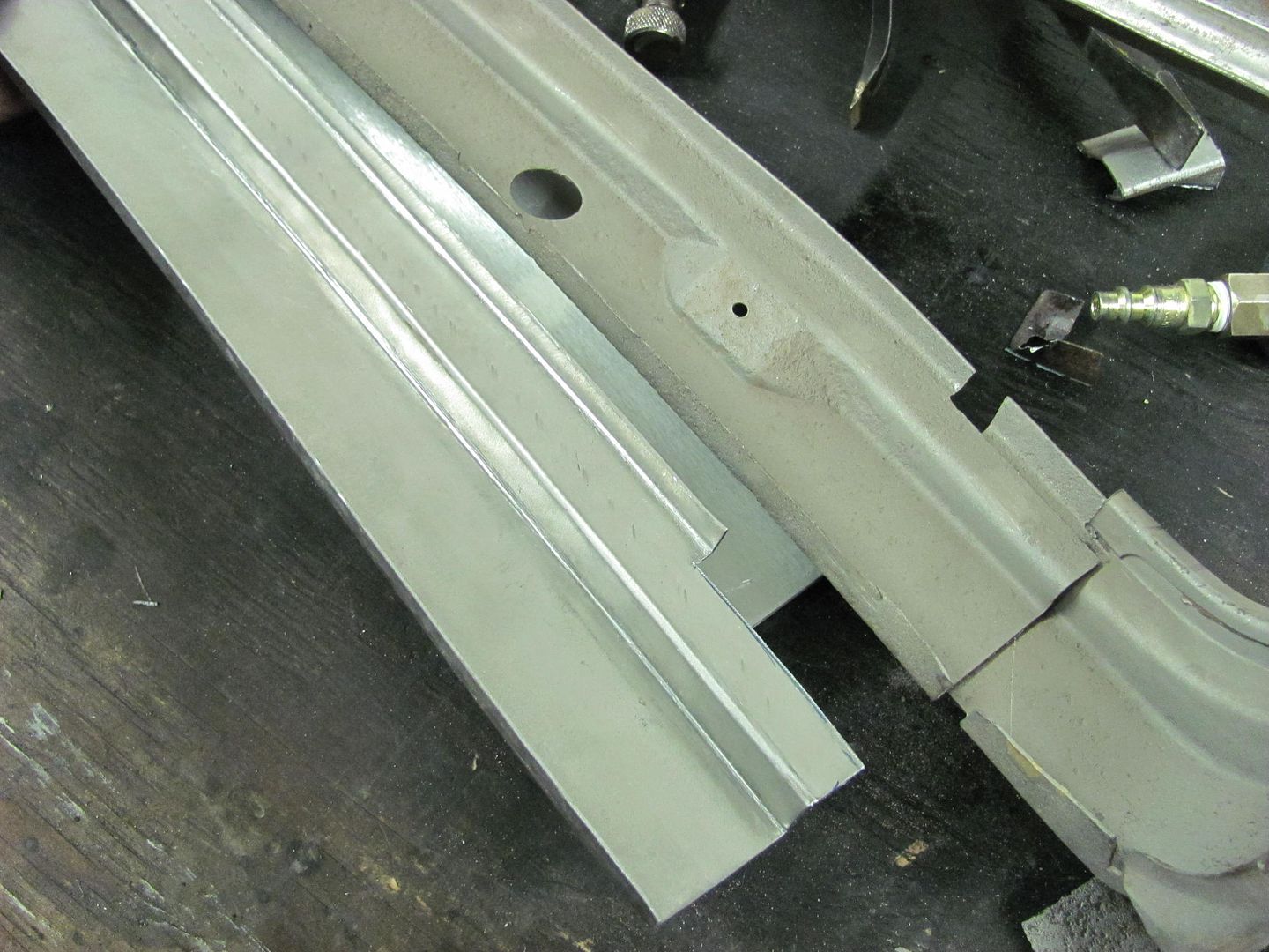
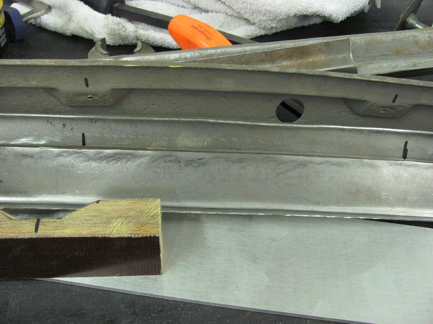
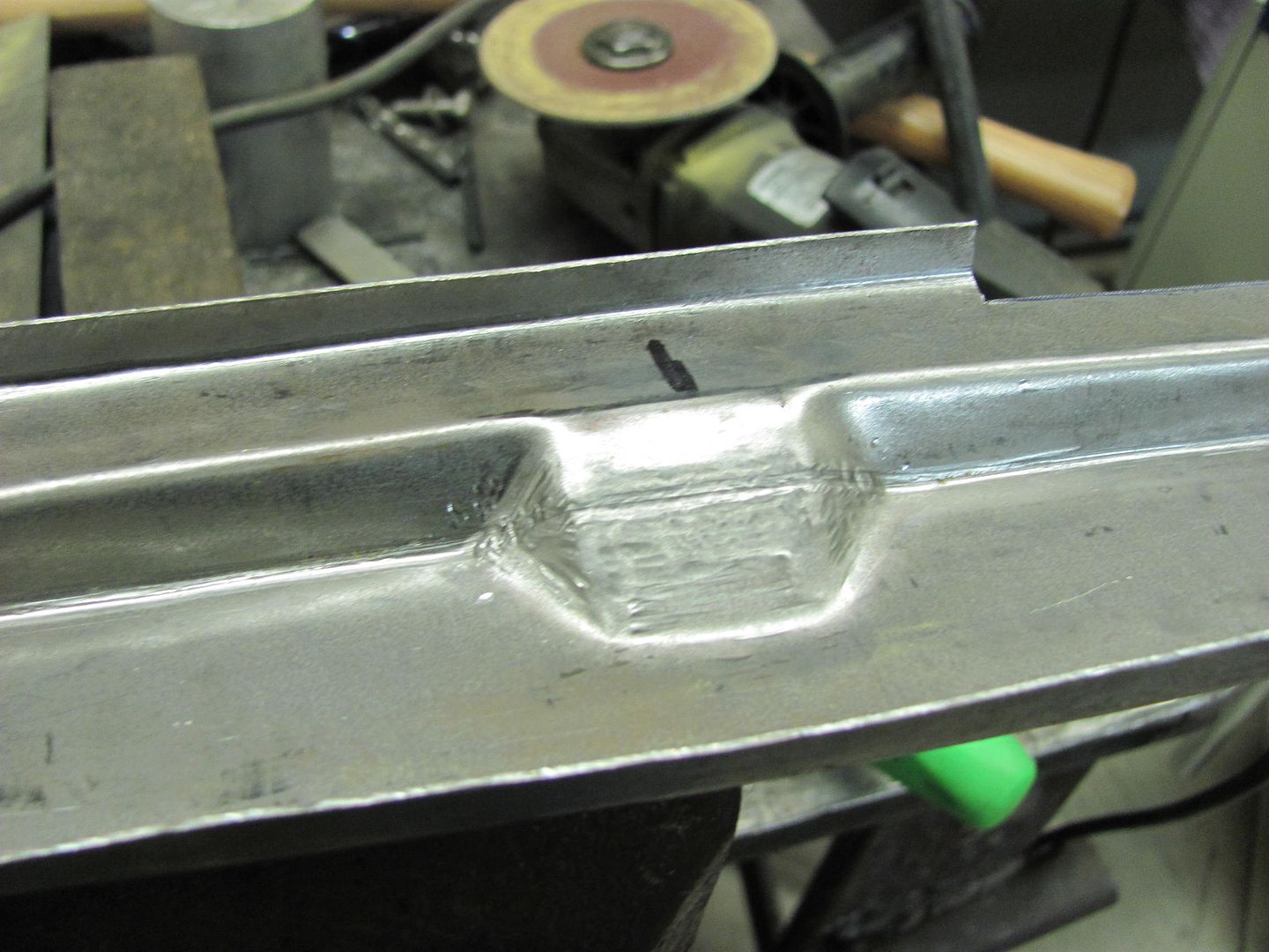
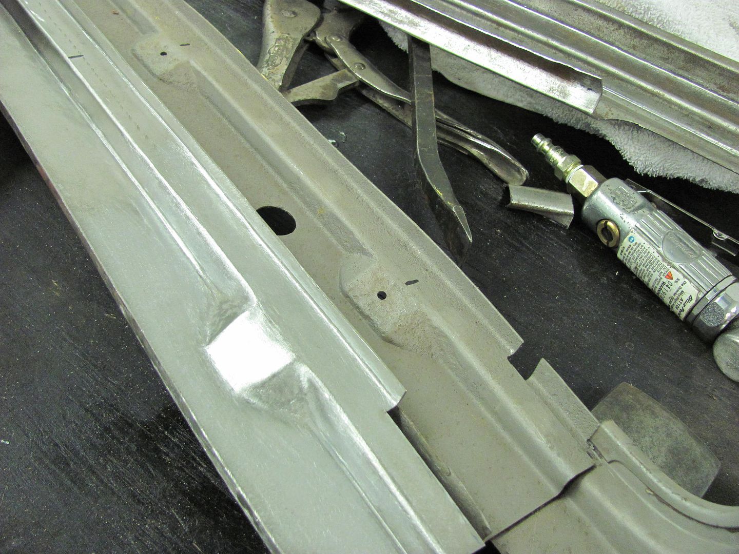
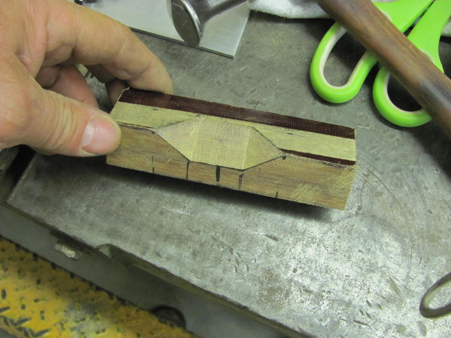
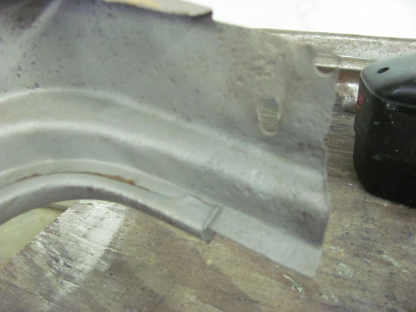
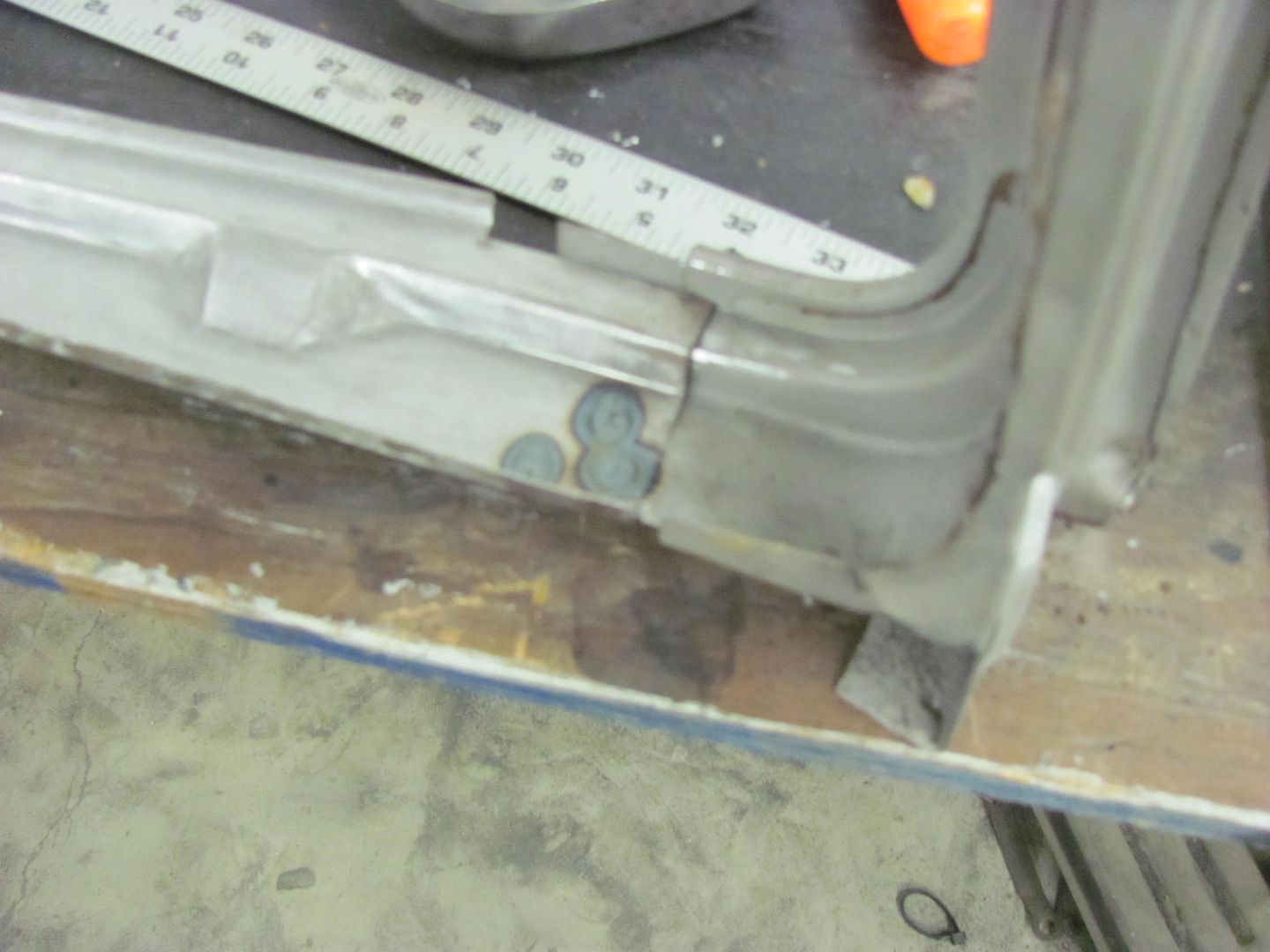
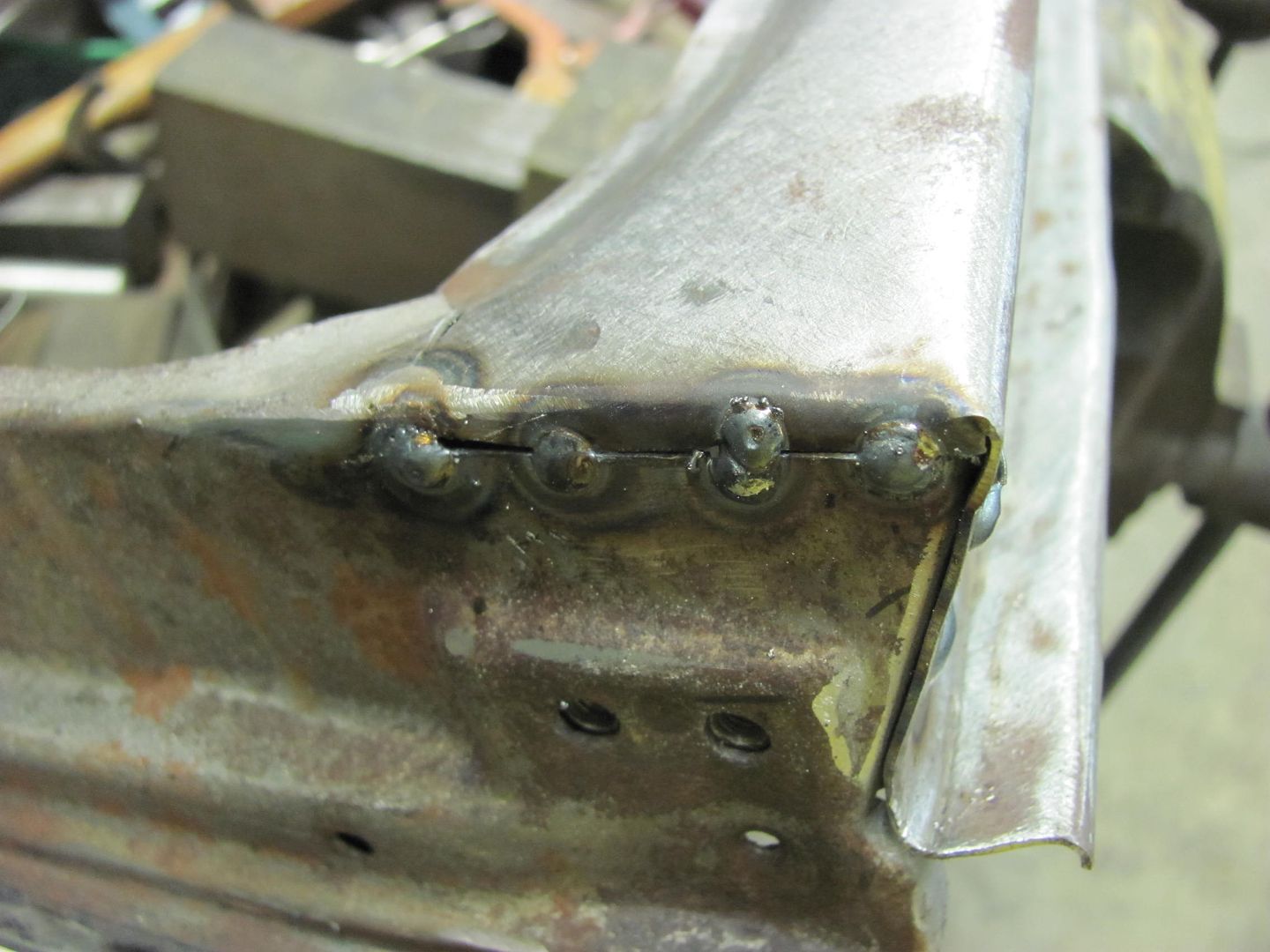
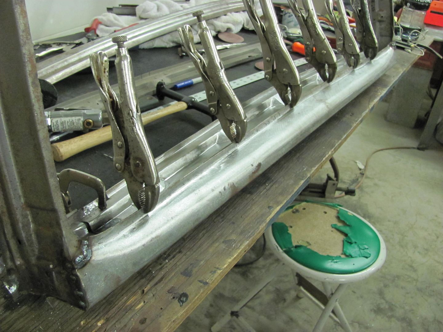
The folded edges along both sides did help to control any other changes in the shape of the panel. I didn't notice much change in the radius, but if needed it can be tweaked on the single fold flange where the bottom outer panel spot welds to it, as this is the main critical fitment on this last piece. The multi-stepped fold is less critical as the outer panel's top flange is inside the window opening and is spot welded to the horizontal area behind those pads, which gives more room for error/adjustment


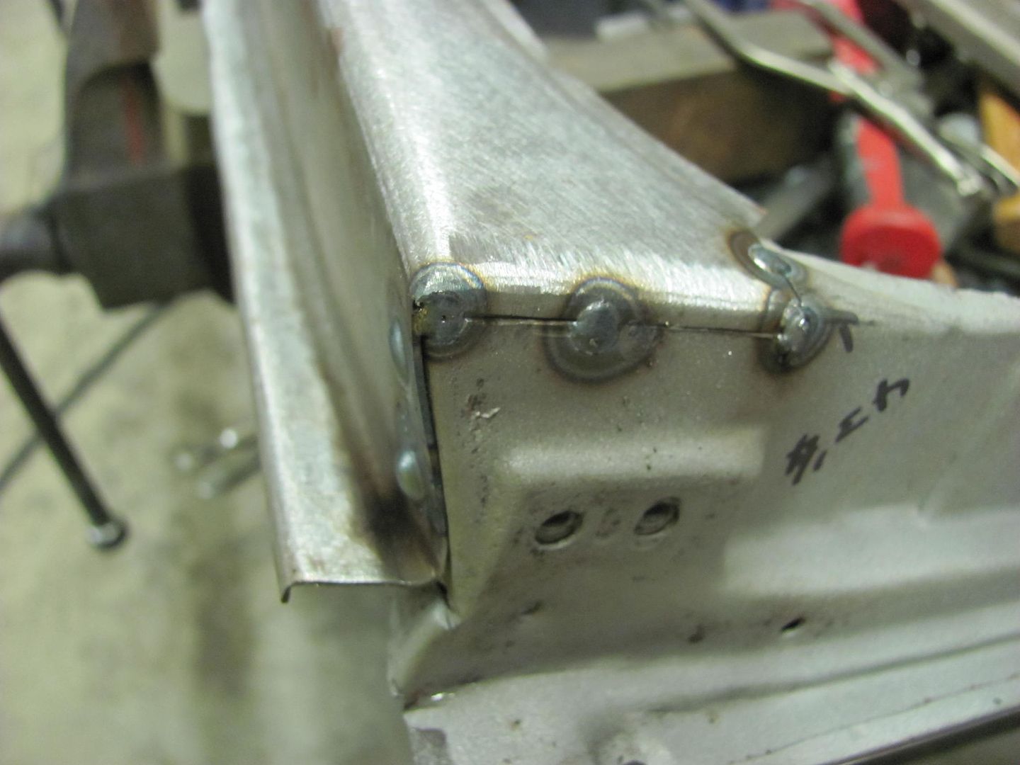
That's about it until next time...