
You are using an out of date browser. It may not display this or other websites correctly.
You should upgrade or use an alternative browser.
You should upgrade or use an alternative browser.
MP&C Shop Projects
- Thread starter MP&C
- Start date
RADcustom
Well-known member
Phenolic
I know it‘s been covered previously, but please remind us what’s the material that you make dies with? It looks like it’s been grabbed from (and would smell like) first gen TV sets.
thanks for all that you share with us,
John/CT
Yes, this is Phenolic, comes in industrial or electrical grade. The electrical is used for circuit boards in electronics or for isolators in electrical busses. Neither one is cheap, but the industrial grade is a bit cheaper of the two.
Some side work in the shop, we had made some wall mounts for a table top touch panel a year or so back and the Tech Rep for the company that made the touch panels had reached out to me recently as they needed some wall mounts for a bank job they were doing in New York. In order to better guarantee consistency, I drew up some in-the-flat drawings and sent them to SendCutSend so we could use laser cut parts this time around.

The customer was installing these in drywall, so we also needed to design a mud ring. We added a flange for support so that this could also be used as a drilling template, resting the flange on the bottom of the hole opening and using clamps to eliminate any movement. The flange width was sized to be half width of our lower dies, so the simple use of a couple rare earth magnets makes the perfect back stop. We included #29 drill bits in the kit in order to drill through the 8-32 press nuts without removing any threads. A 3/16 bit was also included for a generous oversize of the holes in the drywall. And yes, I also included work instructions.


Since the sides of the sleeve for the mount are dictated by equipment and magnet thickness, all of the folded flange widths would need to be sized the same. For better accuracy we opted to use the flange edge against our backstop (vice outer perimeter edge of the mount), so we needed a "shim" of a .323 thick flat bar to provide the needed size.

Back plate gets welded in place; it was sized for its edge to locate half width of the flange for an easy fusion fillet bead.


Test fit....
Then dropped off at The Shop at Shorty's for powder coat finish, some in Black Wrinkle and others in Snowbound White.


The customer was installing these in drywall, so we also needed to design a mud ring. We added a flange for support so that this could also be used as a drilling template, resting the flange on the bottom of the hole opening and using clamps to eliminate any movement. The flange width was sized to be half width of our lower dies, so the simple use of a couple rare earth magnets makes the perfect back stop. We included #29 drill bits in the kit in order to drill through the 8-32 press nuts without removing any threads. A 3/16 bit was also included for a generous oversize of the holes in the drywall. And yes, I also included work instructions.
Since the sides of the sleeve for the mount are dictated by equipment and magnet thickness, all of the folded flange widths would need to be sized the same. For better accuracy we opted to use the flange edge against our backstop (vice outer perimeter edge of the mount), so we needed a "shim" of a .323 thick flat bar to provide the needed size.
Back plate gets welded in place; it was sized for its edge to locate half width of the flange for an easy fusion fillet bead.
Test fit....
Then dropped off at The Shop at Shorty's for powder coat finish, some in Black Wrinkle and others in Snowbound White.
The boss lady had picked up a vintage three-shelved stand a while back, and we had been tripping over the parts in the media blast cabinet.


After media blasting they were sent off to The Shop at Shorty's for a powder coat finish. He had some pastel green in stock so we went with that. Here's the preview picture he sent:

We will get the parts picked up this week. We already ordered new stainless hardware in slotted screws and square nuts for the assembly. Next, the casters seemed in good condition but needed a refinish as well. So the OEM rivets were drilled out so the metal housing could get a Cerakote treatment in gun metal grey. In order to reassemble without rivets we made some faux rivets that will make use of 1/4-20 threads and sleeve retainer loctite to keep things together.


A tap handle in the vise was used to clamp the "rivet" while it was threaded..


The nuts were rounded as well, leaving just enough flat for assembly, to mimic the rounded head rivet as well. Threads trimmed to size and the parts were then polished.


After media blasting they were sent off to The Shop at Shorty's for a powder coat finish. He had some pastel green in stock so we went with that. Here's the preview picture he sent:
We will get the parts picked up this week. We already ordered new stainless hardware in slotted screws and square nuts for the assembly. Next, the casters seemed in good condition but needed a refinish as well. So the OEM rivets were drilled out so the metal housing could get a Cerakote treatment in gun metal grey. In order to reassemble without rivets we made some faux rivets that will make use of 1/4-20 threads and sleeve retainer loctite to keep things together.
A tap handle in the vise was used to clamp the "rivet" while it was threaded..
The nuts were rounded as well, leaving just enough flat for assembly, to mimic the rounded head rivet as well. Threads trimmed to size and the parts were then polished.
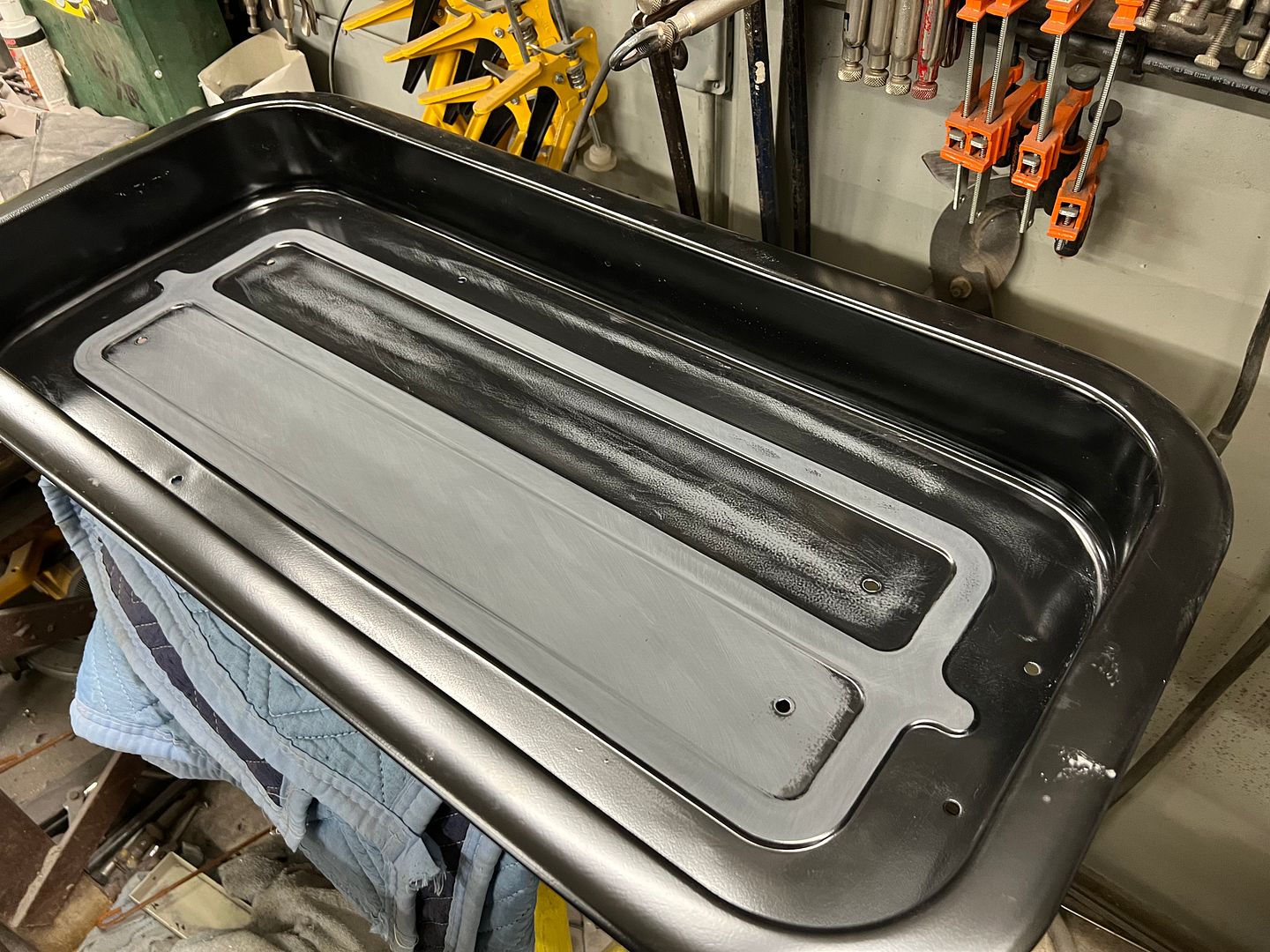
A few months back we had received some newly polished stainless spears (side trim) for the 55 wagon. Part of the payment was to fabricate a "factory delete" plate for the spare tire well of a 55 chevy in gasser form. He wanted to mimic the factory X pattern that is located along the centerline of the trunk. We recently got this done, and with as-installed pictures received, it seems a good time to post this as well. We had tried a sample using the bead roller, and also had made a die set for the Lennox that would produce both sides at once. Neither worked well at all. I didn't care for the bead roller version much at all since we would be relying on self guiding and the possibility of line deviation. So we opted for a set of offset dies that I had for the Lennox, and producing each side individually. The Lennox works well because the linear slide lets us clamp the part and produce multiple parallel embossings with good accuracy.


As primed by the owner... Yes, that is Wisconsin farmland.


Installed...


So there you have it, a rare OEM spare tire delete plate.
As primed by the owner... Yes, that is Wisconsin farmland.
Installed...
So there you have it, a rare OEM spare tire delete plate.
We picked up the powder coated parts from The Shop at Shorty's, for reassembly we had ordered some replacement slotted oval head screws and square nuts in stainless so we could polish them up a bit for a bit of bling.


And no job is complete without undergoing the close scrutiny of the quality control inspector...


And no job is complete without undergoing the close scrutiny of the quality control inspector...
Boosted1
Well-known member
I think the inspector approves. Looks great.
Steering column one step closer to green paint...

and blocked to 500 grit...

Working on removing dings and refining scratches on the windshield trim in prep for polishing. These pieces are less receptive to using the DA due to all the creases, so we've resorted to wet/dry paper up to 2500 and then polish.


Jared getting the hang of this stainless work....

For the other wagon, we went with a powder coat chrome finish to dress up that front dropped axle.
And this is the second round of three coats of epoxy and blocking. Think this will be the last round, and then on to some silver base and blue kandy..
and blocked to 500 grit...
Working on removing dings and refining scratches on the windshield trim in prep for polishing. These pieces are less receptive to using the DA due to all the creases, so we've resorted to wet/dry paper up to 2500 and then polish.
Jared getting the hang of this stainless work....
For the other wagon, we went with a powder coat chrome finish to dress up that front dropped axle.
And this is the second round of three coats of epoxy and blocking. Think this will be the last round, and then on to some silver base and blue kandy..
Last edited:
More work on the wagons. Jared and I continuing to repair some stainless trim. I was asked about our process, so here's a bit more detailed approach. But understand we are complete novices at this, so take any of this with a grain of salt.
To start, some light scuffing in line with 1500 grit helps to highlight any rock dings in the windshield trim..

Once any defects are identified, they are LIGHTLY tapped outward from the back side to bring the defect outward where it can be removed. Then 400 grit is used to remove the defect (and by default some of the adjacent material). So we want the defect to be pronounced outward, but not too much. Better to tap it outward in repeated steps than to go too far and create a stretch. I missed getting a picture before we started on this "rock chip"; this was after a few passes with 400 on the 3M board (just above arrow).. It was tapped outward about 4 different times until we got it where the defect was sanded out.

Back side that was tapped....


After removing all the dings, the surface was sanded working progressively through grits 1200, 1500, 2000, 2500, and then on to 3000 and 5000 trizact discs on the DA. Afterwards it was polished out on the buffer...


Some parts painted green so we can continue with more assembly...


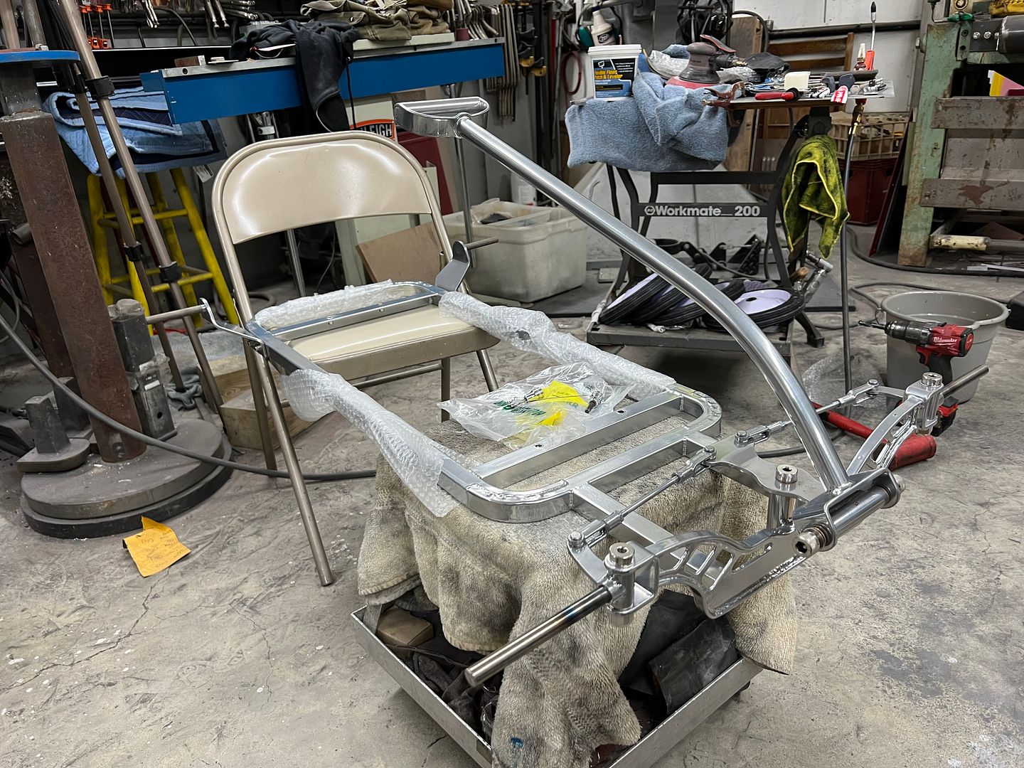
When we had mocked up the wagon frame we just had a 1/2” bolt stuck through the bottom of the pull handle. Now that we’ve got the frame back from chrome powder coating, it’s time for some final details. The bolt for the bottom of the pull handle needs to be an Allen bolt to match our kingpins, and we need one from each side to be symmetrical. A little late to thread any holes in the pivot piece, so we’ll go with docking hardware. A 1/2-13 bolt was turned down for 1/4-20 threads, and the opposite one drilled and tapped.

An allen wrench in the vise holds the bolt for threading


Bolt for the opposite side...


Frame is all done but trimming the axles, now to finish blocking the epoxy on the tub.

To start, some light scuffing in line with 1500 grit helps to highlight any rock dings in the windshield trim..
Once any defects are identified, they are LIGHTLY tapped outward from the back side to bring the defect outward where it can be removed. Then 400 grit is used to remove the defect (and by default some of the adjacent material). So we want the defect to be pronounced outward, but not too much. Better to tap it outward in repeated steps than to go too far and create a stretch. I missed getting a picture before we started on this "rock chip"; this was after a few passes with 400 on the 3M board (just above arrow).. It was tapped outward about 4 different times until we got it where the defect was sanded out.
Back side that was tapped....
After removing all the dings, the surface was sanded working progressively through grits 1200, 1500, 2000, 2500, and then on to 3000 and 5000 trizact discs on the DA. Afterwards it was polished out on the buffer...
Some parts painted green so we can continue with more assembly...
When we had mocked up the wagon frame we just had a 1/2” bolt stuck through the bottom of the pull handle. Now that we’ve got the frame back from chrome powder coating, it’s time for some final details. The bolt for the bottom of the pull handle needs to be an Allen bolt to match our kingpins, and we need one from each side to be symmetrical. A little late to thread any holes in the pivot piece, so we’ll go with docking hardware. A 1/2-13 bolt was turned down for 1/4-20 threads, and the opposite one drilled and tapped.
An allen wrench in the vise holds the bolt for threading
Bolt for the opposite side...
Frame is all done but trimming the axles, now to finish blocking the epoxy on the tub.
shortykorte
Well-known member
Awesome seeing the 55 assembly has begun.
Didn’t realize I had a powder coating shop.
Didn’t realize I had a powder coating shop.
PugetDude
ALLIANCE MEMBER
You ARE a man of many talents, Shorty.Awesome seeing the 55 assembly has begun.
Didn’t realize I had a powder coating shop.
stinkity stoink
Well-known member
Can’t wait to see the wagon complete !!
Thanks for all the comments fellas..
A quick job in the shop to finish off a junction box lid for a data center. A scissor lift took out the old one. A local machine shop made the lid and needed a recess added for the lock cylinder.

I have a lock reforming tool from MAC tools that looked close to the original but the offset was not quite as deep. So some 1/2" washers were stacked on the punch and a spacer machined on the lathe for the die.


Comparison, that will do the job...

Back to our stainless trim, we need to modify the upper door trim to hold our peep mirrors. We opted for the old school look of the peep mirrors but did not want to use the clamp on paint chippers. The front edge of the trim uses a machine screw through the door and into a nut plate. Our plans are to use a formed hole in the trim and use the hole in the door to attach the mirrors.


As we had used the tail stock of the South Bend before with success, we made some press dies to match the mirror's stepped end and provide a flange in the holes for added strength.


Trial test of the mirror, yellow rag hung outside the rear window for a more visible reflection


A quick job in the shop to finish off a junction box lid for a data center. A scissor lift took out the old one. A local machine shop made the lid and needed a recess added for the lock cylinder.
I have a lock reforming tool from MAC tools that looked close to the original but the offset was not quite as deep. So some 1/2" washers were stacked on the punch and a spacer machined on the lathe for the die.
Comparison, that will do the job...
Back to our stainless trim, we need to modify the upper door trim to hold our peep mirrors. We opted for the old school look of the peep mirrors but did not want to use the clamp on paint chippers. The front edge of the trim uses a machine screw through the door and into a nut plate. Our plans are to use a formed hole in the trim and use the hole in the door to attach the mirrors.
As we had used the tail stock of the South Bend before with success, we made some press dies to match the mirror's stepped end and provide a flange in the holes for added strength.
Trial test of the mirror, yellow rag hung outside the rear window for a more visible reflection
stinkity stoink
Well-known member
Those mirrors look slick installed in the trim !!
Thanks guys! We wanted old school look but smooth details... and no paint chips from a clamp-on bracket.
Some more fabrication work for the day job, we had a door seal that was being abraded by a non-skid strip on the threshold, and wanted to drop it down some as well for better clearance. So a new threshold was made from 16 Gauge #4 brushed stainless. Where the old used countersunk holes for the #8 screws, we opted for the more correct version of dimpled holes. Provides more contact area for better seated hardware.

Dies were made for the dimpling process, they used a 1/4" shank just pushed into a drilled hole in some bar stock vs. welding together. This will allow quick changeout for other sizes/shapes of dies for use in the press brake.


Next, to gain a bit more clearance for the door seal, the new threshold was located and the protrusions of the rubber flooring were scored with a utility knife at the threshold edge. Next, we used a multi-tool to shave down these protrusions that would be beneath the threshold. This wasn't much, but better than what was there before.


Back on wagon duty, we've been continuing on stainless polishing. We had been doing some of the shorter sections by sanding on top of my 4 wheel shop stool as it has a nice flat top surface.

Once we got to the longer sections of trim, this became too cumbersome, so some 1/2" MDF was repurposed as a "holding fixture" while we refined the damaged scratches and dings. A Black Diamond longboard was used with 500 grit PSA paper to highlight any low spots, high spots, or other carnage. Then some LIGHT DUTY metal bumping to address the issues and a repeat of the highlighting sanding. Once all the defects were addressed, we then worked progressively through 600, 1200, 1500, 2000, and 2500 w/d paper. Then 3000 and 5000 Trizact, and finally on to the buffer.
A modification of our "fixture" to hold the curved end of the trim...

Jared helps out here to help stabilize the skinny trim and keep it from flopping around. Once quick mis-step at this point is about an hour minimum of recovery.
Nice reflection of the door opener in the ceiling after buffing...

trim clips added...


...and our driver's mirror added...


Some more fabrication work for the day job, we had a door seal that was being abraded by a non-skid strip on the threshold, and wanted to drop it down some as well for better clearance. So a new threshold was made from 16 Gauge #4 brushed stainless. Where the old used countersunk holes for the #8 screws, we opted for the more correct version of dimpled holes. Provides more contact area for better seated hardware.
Dies were made for the dimpling process, they used a 1/4" shank just pushed into a drilled hole in some bar stock vs. welding together. This will allow quick changeout for other sizes/shapes of dies for use in the press brake.
Next, to gain a bit more clearance for the door seal, the new threshold was located and the protrusions of the rubber flooring were scored with a utility knife at the threshold edge. Next, we used a multi-tool to shave down these protrusions that would be beneath the threshold. This wasn't much, but better than what was there before.
Back on wagon duty, we've been continuing on stainless polishing. We had been doing some of the shorter sections by sanding on top of my 4 wheel shop stool as it has a nice flat top surface.
Once we got to the longer sections of trim, this became too cumbersome, so some 1/2" MDF was repurposed as a "holding fixture" while we refined the damaged scratches and dings. A Black Diamond longboard was used with 500 grit PSA paper to highlight any low spots, high spots, or other carnage. Then some LIGHT DUTY metal bumping to address the issues and a repeat of the highlighting sanding. Once all the defects were addressed, we then worked progressively through 600, 1200, 1500, 2000, and 2500 w/d paper. Then 3000 and 5000 Trizact, and finally on to the buffer.
A modification of our "fixture" to hold the curved end of the trim...
Jared helps out here to help stabilize the skinny trim and keep it from flopping around. Once quick mis-step at this point is about an hour minimum of recovery.
Nice reflection of the door opener in the ceiling after buffing...
trim clips added...
...and our driver's mirror added...
Hellpig
Well-known member
As always, beautiful work!
I think you've somehow created a talent vacuum in the rest of the county, lol.
At least that's what I tell myself when I finish another hack job!
I think you've somehow created a talent vacuum in the rest of the county, lol.
At least that's what I tell myself when I finish another hack job!
txvwnut
Well-known member
Little scrub and rub and that’ll be another amazing wagon to come out of your shop.
I just wanted to thank Robert for giving my son and I a tour of his shop today. It was impressive to see in-person how he crafts his work and the amazing level of finish and perfection that is possible, and yet how this level of work is not a mystery but is the result of hard work and experience, and ultimately achievable.
Afterwards I asked my son if he felt like doing rocker panels on his car seemed more possible after seeing Robert’s shop and what he was able to create. Unfortunately, instead of feeling empowered he said it seemed more intimidating than he thought, but I can see his POV: the level of finish we saw was amazing.
We just need to get started so he can get some confidence, but at least now he knows that it is possible. Thanks Robert! We really appreciated the tour! And the car show at Olde Breton Inn was also fantastic!
steves_001
Well-known member
Love that blue! very nice little wagon.
Hellpig
Well-known member
I just wanted to thank Robert for giving my son and I a tour of his shop today. It was impressive to see in-person how he crafts his work and the amazing level of finish and perfection that is possible, and yet how this level of work is not a mystery but is the result of hard work and experience, and ultimately achievable.
I prefer to think that work of that quality is the result of witchcraft and/or voodoo.
Makes me feel better about my hackery, lol.
Saturday we did some more Stainless scratch refinement... Two long pieces left to go. and one on order. Dana had taken one somewhere for straightening, and the results left us with a wrinkle and a crack forming. So that one's replacement is on the way from The Stainless Shoppe.


Jared putting the eagle eye on the remaining stainless to find any defects...

Reassembling the steering column after painting...


some heat shrink was added to the harness to help prevent abrading against the steering shaft. Our steering wheel puller kit did not have the needed parts for compressing the spring for the ts cam/horn ring, so we made a push ring and modified some 5/16 bolts for the cause. Much cheaper than grinding on the snap on parts.


Sunday morning I did a shop tour for Pete, his son, and his neighbor. Always good to show some of the processes to the younger crowd to spark some interest. And alas, I was too busy running my mouth to take pictures... After that we loaded up the wagon for it's maiden voyage, a shakedown run at Eddie's Brunch and Car Show, located at Bailey's Olde Breton Inn. This isn't a real large show (although it grows every year) but it's one of those must attends, and all the proceeds benefit our local Hospice.
Some takeaways on the wagon design, the pull handle length that was designed for a small child inside the wagon was too short for a 6' tall fella with a long stride. Felt like yap dogs at my heels . And I think the frame design may need air bags, where it did well on the pavement, there was quite a bit of drag (rolling resistance) with the grass up in the frame.


*Car show pictures borrowed from FB
Jared putting the eagle eye on the remaining stainless to find any defects...
Reassembling the steering column after painting...
some heat shrink was added to the harness to help prevent abrading against the steering shaft. Our steering wheel puller kit did not have the needed parts for compressing the spring for the ts cam/horn ring, so we made a push ring and modified some 5/16 bolts for the cause. Much cheaper than grinding on the snap on parts.
Sunday morning I did a shop tour for Pete, his son, and his neighbor. Always good to show some of the processes to the younger crowd to spark some interest. And alas, I was too busy running my mouth to take pictures... After that we loaded up the wagon for it's maiden voyage, a shakedown run at Eddie's Brunch and Car Show, located at Bailey's Olde Breton Inn. This isn't a real large show (although it grows every year) but it's one of those must attends, and all the proceeds benefit our local Hospice.
Some takeaways on the wagon design, the pull handle length that was designed for a small child inside the wagon was too short for a 6' tall fella with a long stride. Felt like yap dogs at my heels
. And I think the frame design may need air bags, where it did well on the pavement, there was quite a bit of drag (rolling resistance) with the grass up in the frame.*Car show pictures borrowed from FB
Last edited:
Hellpig
Well-known member
*Car show pictures borrowed from FB
Well, THAT explains the sweet Honda minivan pic...
We have an upcoming job in the shop to weld up some stainless tubing, so to gear up for that, we need to be able to back-purge the inside.

A piece of brass was sourced from the scrap pile to fabricate an adaptor for our Argon fitting. We had ordered high temperature rubber stoppers from McMaster, and since I had some 5/16-18 wing nuts in stock, we chose that as our size option for through the rubber stopper, with the opposite end tapped for 1/4-18 NPT. Then a .109 through hole was added.


A rubber sealing washer added to the mix....


and that should do the trick for us..
A piece of brass was sourced from the scrap pile to fabricate an adaptor for our Argon fitting. We had ordered high temperature rubber stoppers from McMaster, and since I had some 5/16-18 wing nuts in stock, we chose that as our size option for through the rubber stopper, with the opposite end tapped for 1/4-18 NPT. Then a .109 through hole was added.
A rubber sealing washer added to the mix....
and that should do the trick for us..
Last edited:
zmotorsports
ALLIANCE MEMBER
Nice job on the wagon Robert. That blue really pops in the sun. You're going all out, I'm just keeping the factory red tub with Radio Flyer badging on my grandson's wagon.
I also learned about the short handle on my first wagon build back in the early 90's, so I will be making two handles for this one that can interchangeable. Both my son and DIL are quite tall so a longer handle for when he's young and the wagon can be pulled without hitting their ankles and a shorter one for my grandson to use as he gets older from the sitting in the tub position.
I also learned about the short handle on my first wagon build back in the early 90's, so I will be making two handles for this one that can interchangeable. Both my son and DIL are quite tall so a longer handle for when he's young and the wagon can be pulled without hitting their ankles and a shorter one for my grandson to use as he gets older from the sitting in the tub position.
Boosted1
Well-known member
Wagon looks great.
Re the handle length, can you chop it in half and add a telescope feature with a pin.
For grass, maybe just some bigger times ( width and diameter ) that hold air.
Rest of fab work too nice to change.
Re the handle length, can you chop it in half and add a telescope feature with a pin.
For grass, maybe just some bigger times ( width and diameter ) that hold air.
Rest of fab work too nice to change.
BORING HOP YARD
Well-known member
I like the results from the tig spot welds, I will be trying that in the future for sure.
Thanks to Jesse Harris and Robert for sharing!
Thanks to Jesse Harris and Robert for sharing!
txvwnut
Well-known member
Good to see that process in world time. Eastwood sells a Tig spot weld kit that has a special cup and a visegrip alignment tool. I contemplated buying it but after seeing this I might give a shop made tool a try.
Rockable
Well-known member
Great work, Jesse! Thanks for sharing, Robert!
Rockable
Well-known member
Sorry I missed it. That is one sweet looking Stude! Is that a restore or a scratch build?
bowtiguy
Well-known member
Robert, thank you SO much for the detailed stainless trim restoration procedure. Ill be tackling the front & rear window trim on my 67’ vette this weekend in time to ship it back to illinois for installation next weekend. I have an eastwood buffer i used to do the trim on my 68’ C10 restomod along w/ the correct wheels. What buffing compound do you prefer for final polish?
Sorry I missed it. That is one sweet looking Stude! Is that a restore or a scratch build?
Not sure if Jim had restored it, but that is definitely the caliber of his work. He did have quite a few cars in the shop undergoing wood structure fabrication and repairs.
Robert, thank you SO much for the detailed stainless trim restoration procedure. Ill be tackling the front & rear window trim on my 67’ vette this weekend in time to ship it back to illinois for installation next weekend. I have an eastwood buffer i used to do the trim on my 68’ C10 restomod along w/ the correct wheels. What buffing compound do you prefer for final polish?
The "scratch refinement" we do using the various grits of w/d paper and the 3M Trizact have eliminated our first two steps of the buffing process. The first wheel was the sisal wheel, which actually adds scratches in the process of removing larger defects. So along the theory that our process should not cause more damage, I was glad to eliminate this step, as I could see it adding inconsistently sized scratches. It was actually this that caused me to search for alternative methods and led to what we use presently. Our first wheel used after our scratch refinement is a spiral sewn wheel using green compound, the final is loose wheel using white compound.
Buffing Compounds | Empire Abrasives
Buffing Compounds are used for, coloring, creating luster, and more. Buffing Compound Bars in Black, Blue Rouge, Tripoli, Pink & Green. Check out our stock of long lasting and great value compounds.
 www.empireabrasives.com
Last edited: