
You are using an out of date browser. It may not display this or other websites correctly.
You should upgrade or use an alternative browser.
You should upgrade or use an alternative browser.
MP&C Shop Projects
- Thread starter MP&C
- Start date
jkherd
Well-known member
 I look forward every to entry, always very informative.
Last edited:
Ryf
Well-known member
subscribing. very cool thread thank you for sharing.
alpinewhite
Well-known member
If I were to go to a metal supply shop for some sheet metal to use for body work, what kind should I be looking for? What gauge (16?) and what type (cold rolled, etc?). Sorry for the newbie question. I'm not a bodywork guy.
Ryf
Well-known member
Same thickness as the metal your working on. Early cars per 60's are often 16 gauge. 18 gauge is 70's and mid 80's new stuff is 20 and 22. This isn't scientific and someone else might have a better way to answer.
Imo best answer is when you cut back to good metal and get rid of paint and putty use a micrometer and buy the closest gauge to the measurement.
Where I live you take the steel they have. Lol so no clue on cr or hr etc.
Imo best answer is when you cut back to good metal and get rid of paint and putty use a micrometer and buy the closest gauge to the measurement.
Where I live you take the steel they have. Lol so no clue on cr or hr etc.
Last edited:
Is there a particular reason for using ER70S-7 over dash 6? Easier to grind down? Stronger?
My findings, I replaced one roll of -6 with a roll of -7, and without changing any welder settings, noticed a flatter weld (better wetting to the surface metal) and softer for easier planishing and grinding. I was looking for Esab's EZ-grind at my local welding supply, they indicated it was no longer made (which I have not verified, so don't take that as gospel) and he recommended the -7 as a replacement.
If I were to go to a metal supply shop for some sheet metal to use for body work, what kind should I be looking for? What gauge (16?) and what type (cold rolled, etc?). Sorry for the newbie question. I'm not a bodywork guy.
As mentioned above, check what you have with a set of micrometers. Although I can't agree with early cars being 16ga. I have two 50's era vehicles in the shop, one an F7 truck, the other a 55 handyman wagon. Both have 19 ga for exterior sheet metal. WIth manufacturing and cost cutting what they are, you will typically find metal today being made to the lower end of the tolerance scale on thicknesses, so if you can find 18 ga locally, it should be about the closest to the factory 19. IMO 20 ga is too thin of a match for replacing 19, but to each their own.
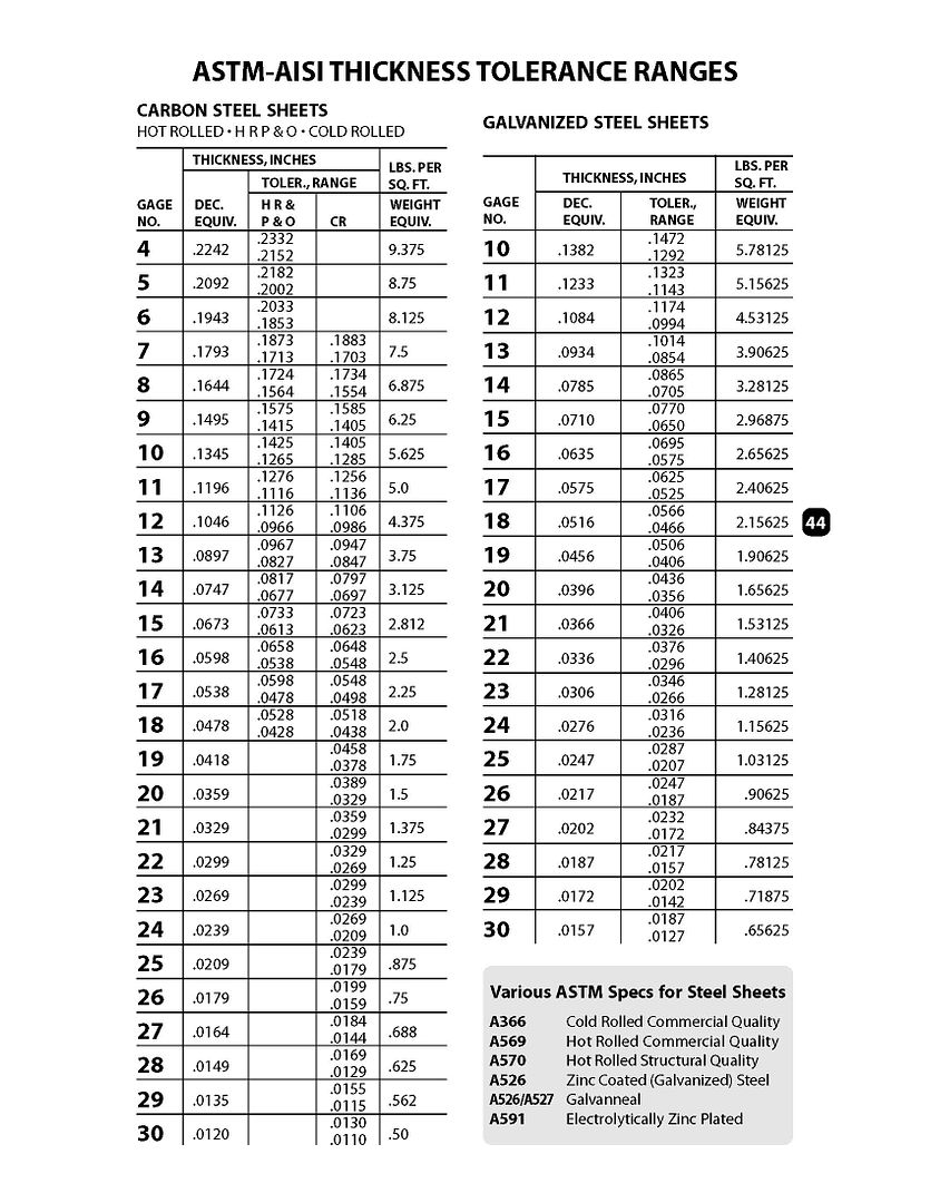
For some samples, here is a 1952 Ford hood and a 1955 Chevy hood that I just happened to have lying around....


Now looking at this ASTM chart, you can see that both these readings fall within the tolerances for 19 ga cold rolled steel.
Regarding cold rolled vs hot rolled, hot normally comes with a mill scale that is a pain to remove, cold may have a slight oil film to help prevent flash rust. The oil residue is much easier to remedy than the mill scale, I'd recommend the cold rolled steel.
Last edited:
Kevin54
MEMBER EMERITUS
It would have been nice if the older vehicles were 16 gage. I would say they were 18 or 19 depending on the section of the vehicle as MP&C shows above. I was lucky enough to have been at the age where my dad taught me how to bang out some dents, work them, hit them with a body file, and never use any lead, or bondo at all. Not only was it an experience, it was also an art as shown in this thread. I also learned how to do leadwork which is really a dieing art now. My dad started at a real young age learning how to work lead, then paint, which led to him starting his own body shop. He was well known around the area and by many others in the business for the quality of work that he did. He taught me to paint at the age of 13, and later on, I ended up doing all of the painting because the years of smoking, and fumes took it's toll on him. He toughed it out until he made it to 95. I'm proud to have learned my skills from him, although it's been quite a few years since I have done any of it. The last was my '93 Silverado that I repaired the cab corners and the frontend where it was wrecked, then redid the complete truck.
If anyone today has the opportunity to know a person like MP&C in your area, that does work like it used to be done, become friends with them and if anything, help them out for free in turn for learning the old skills that someday most will not know. Todays younger ones think they are bodymen if they can unbolt a dented fender and put a new one on. Or slap a little mud on a dent, sand it flat, and think they rebuilt the complete car. Banging out dents, working the metal, making new pieces, and even leadwork is a dieing art. I consider us lucky that MP&C is taking the time to show us the correct way to do things. It not only takes time to make the part, it is taking a lot of his time out of his day, almost everyday, to take photo's and do a tutorial.
So with that, I say thank you and
Omphaloskeptic
Well-known member
"So with that, I say thank you and"
^+1 Big time!
"^+1 Big time!
Guys, thanks for the kind words. I've had plenty of help/guidance myself over the years, and just like the metalshaping workshop I attended this weekend, everyone can share ideas and methods, and still learn from someone else at the same time.. We stop learning when we stop sharing. It's a give and take, I'm just doing my part.
Ryf
Well-known member
I was so sure you were wrong! but yeah I was.. I went out and micrometered some scraps and its 19 gauge, I was going off memory and sometimes its not good anymore. thanks for catching my brain fart lol.
No sweat, I've been there myself. I try to have backup for my ramblings now, hence all the pictures. 
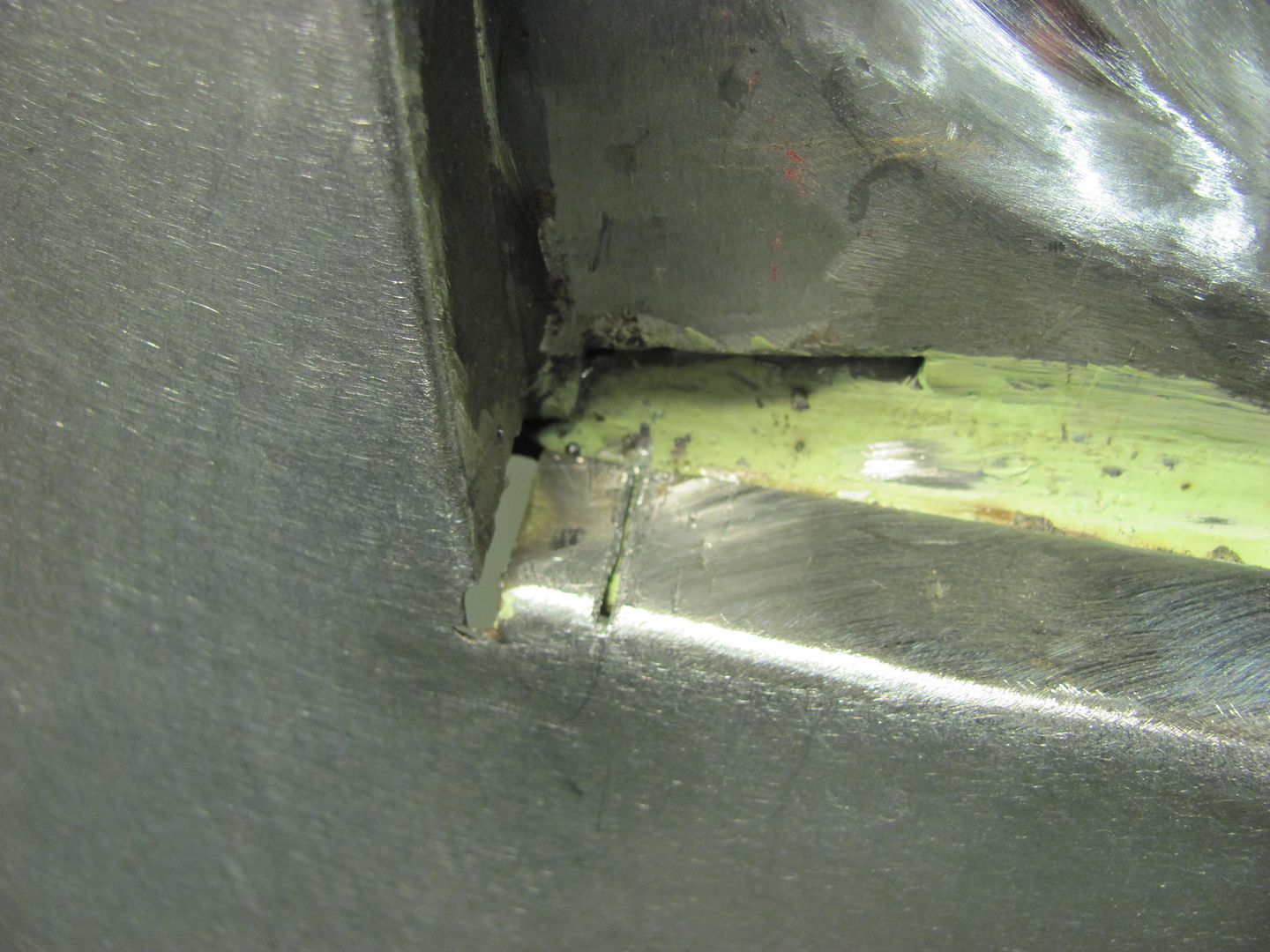
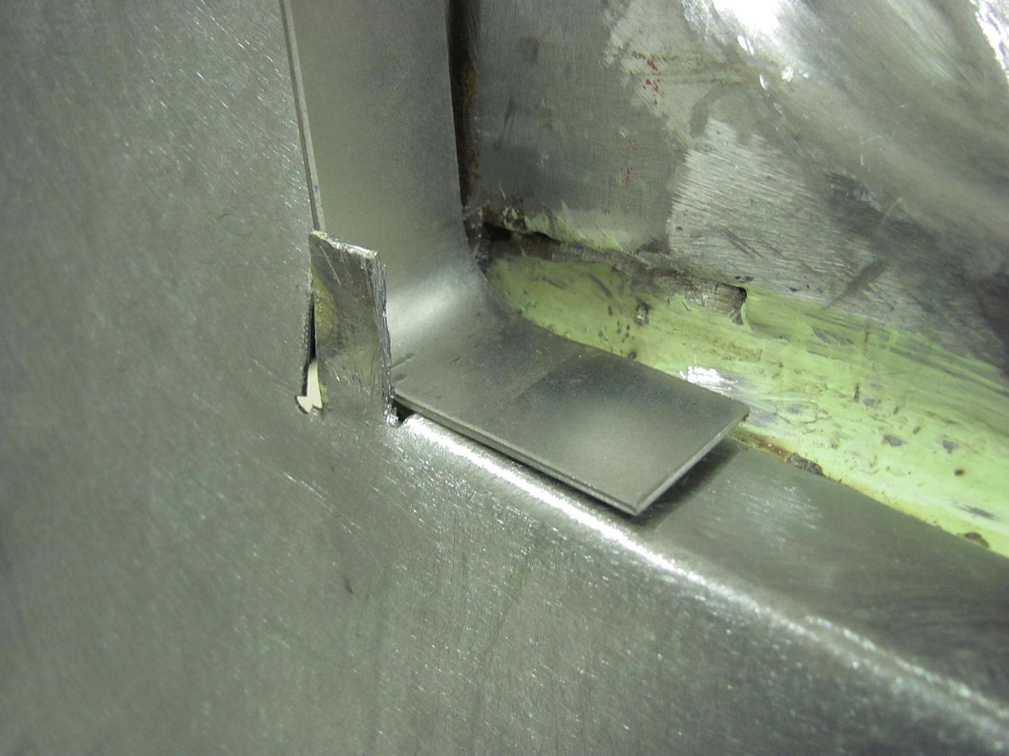
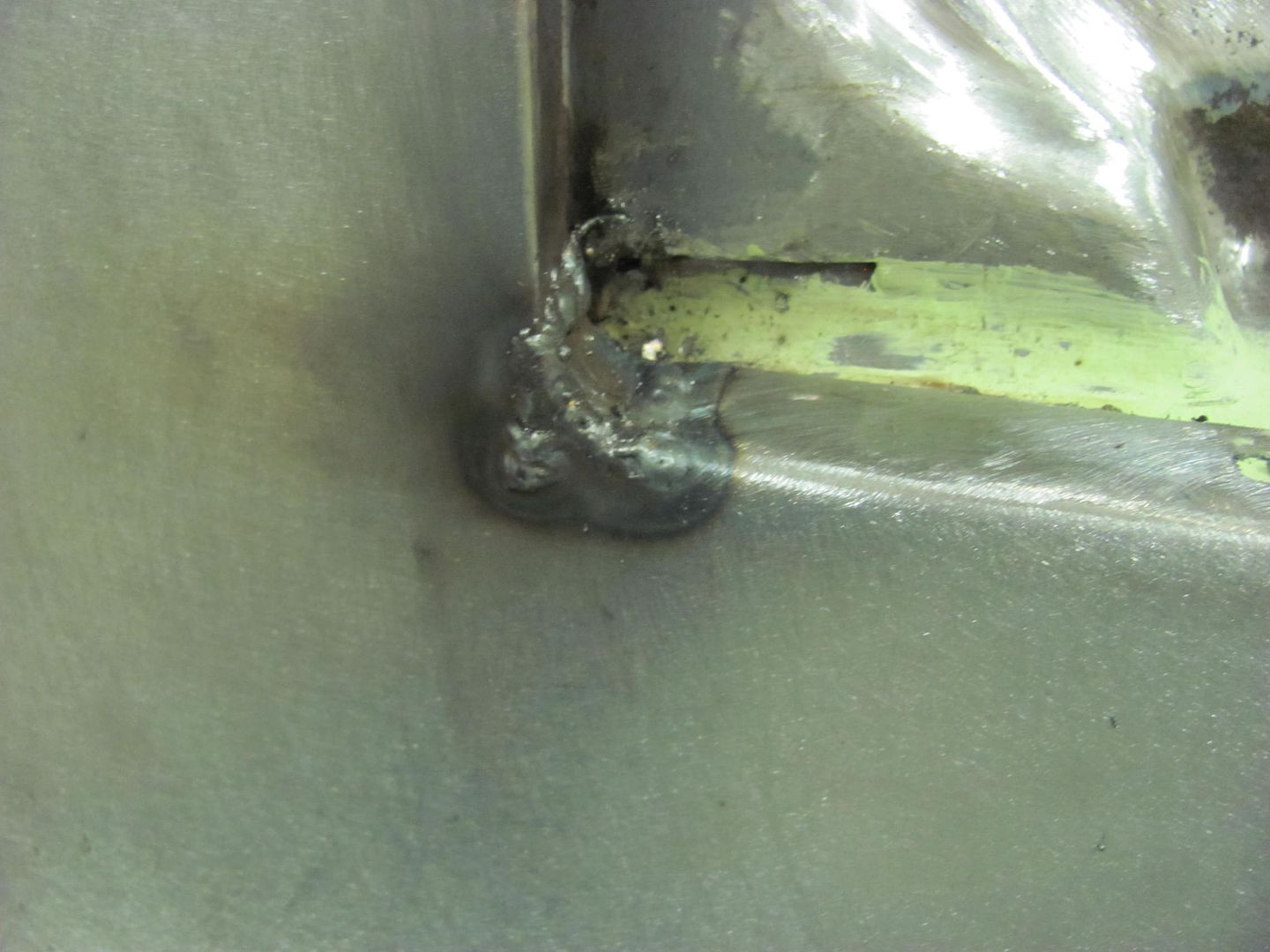
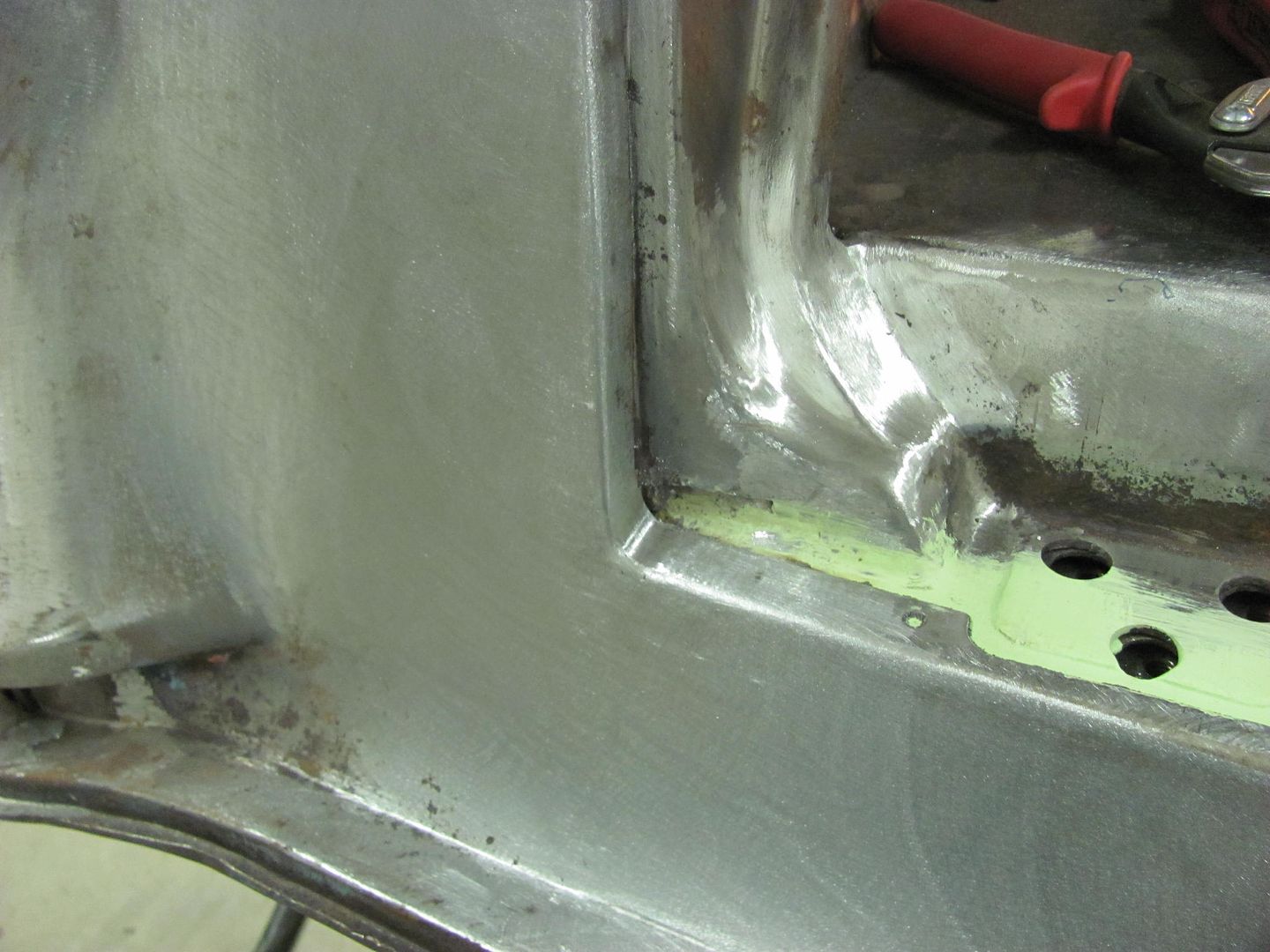
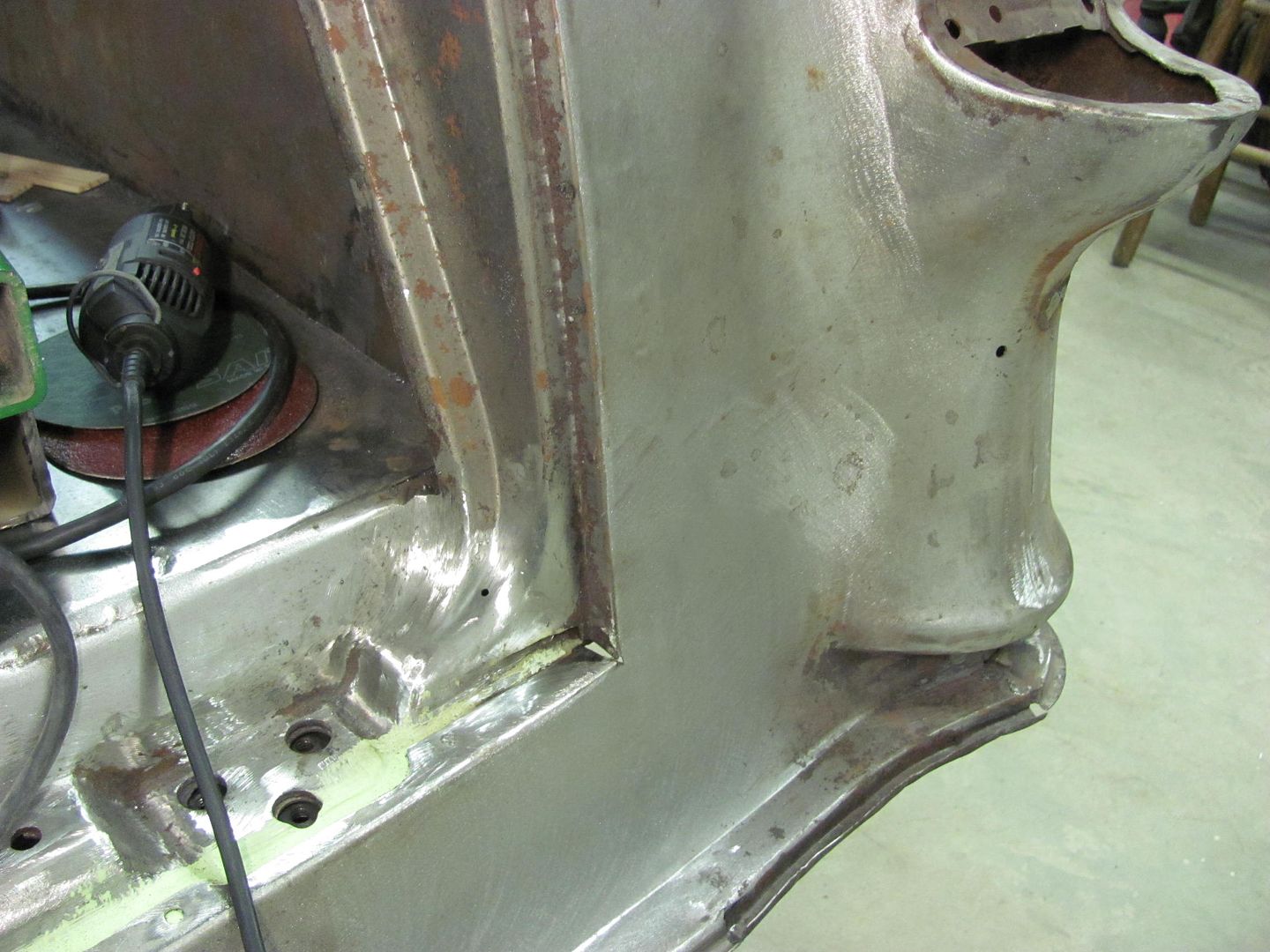
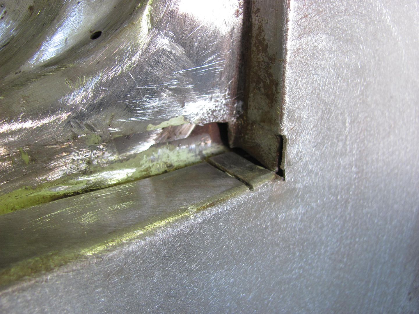
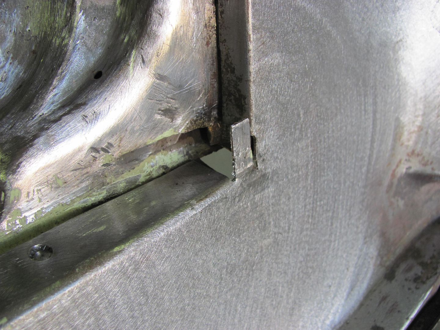
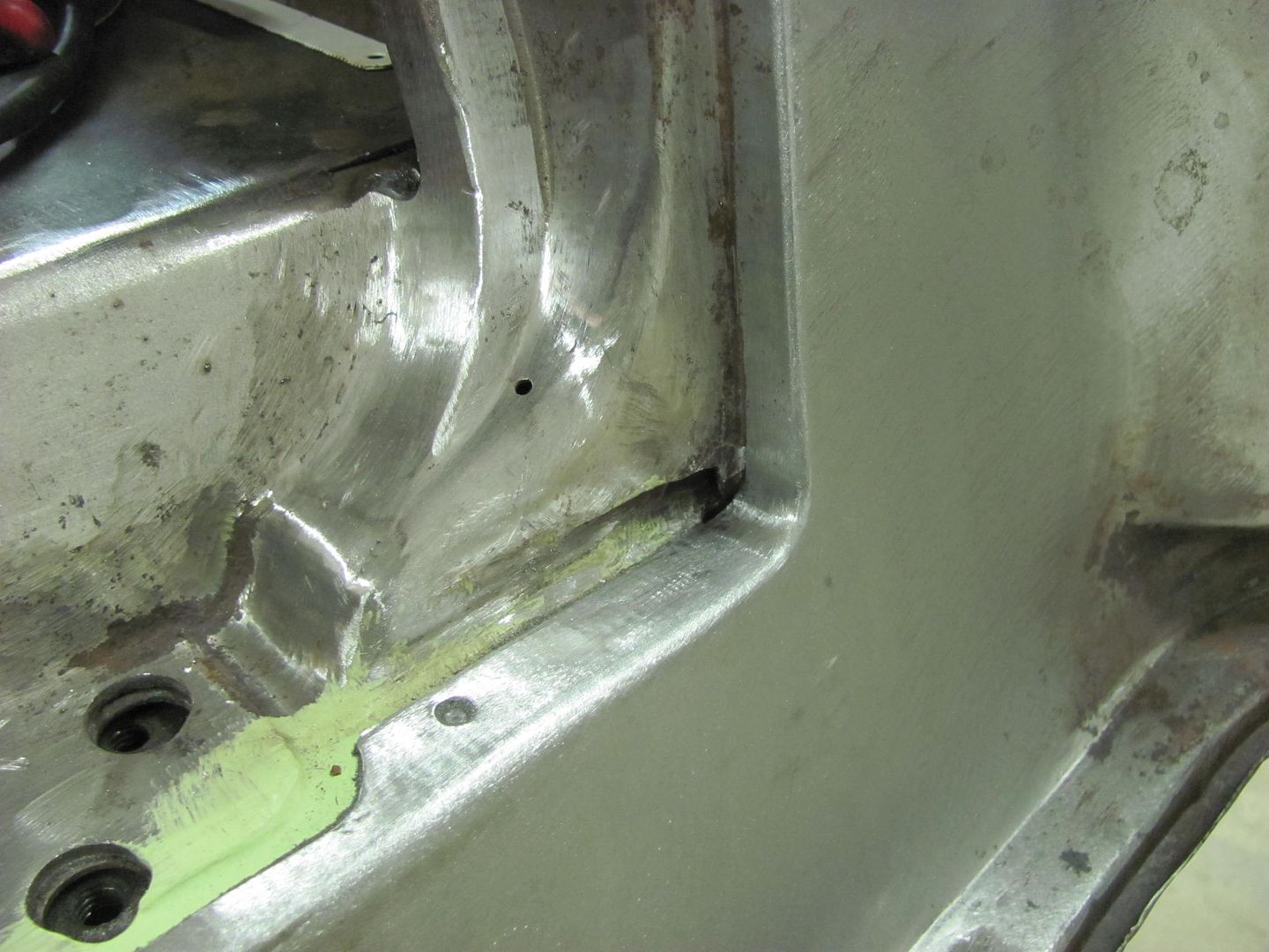
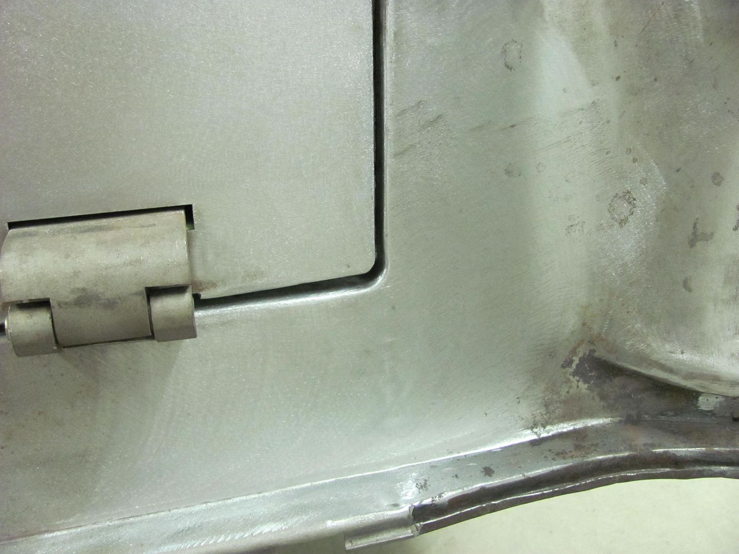
Thought I'd spend some time this evening to see how I could clean up these corners....
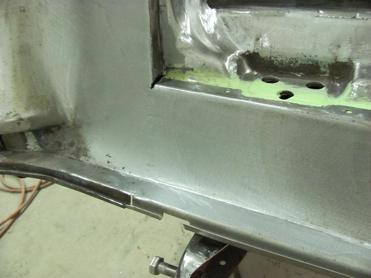
Trimming out some of the excess...
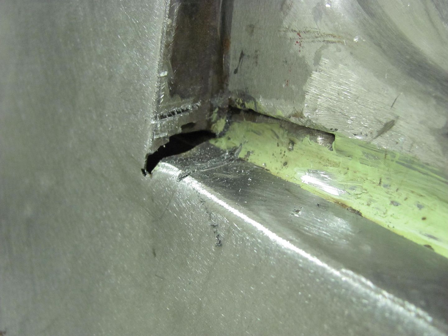
Used the roll former die to make the radius....

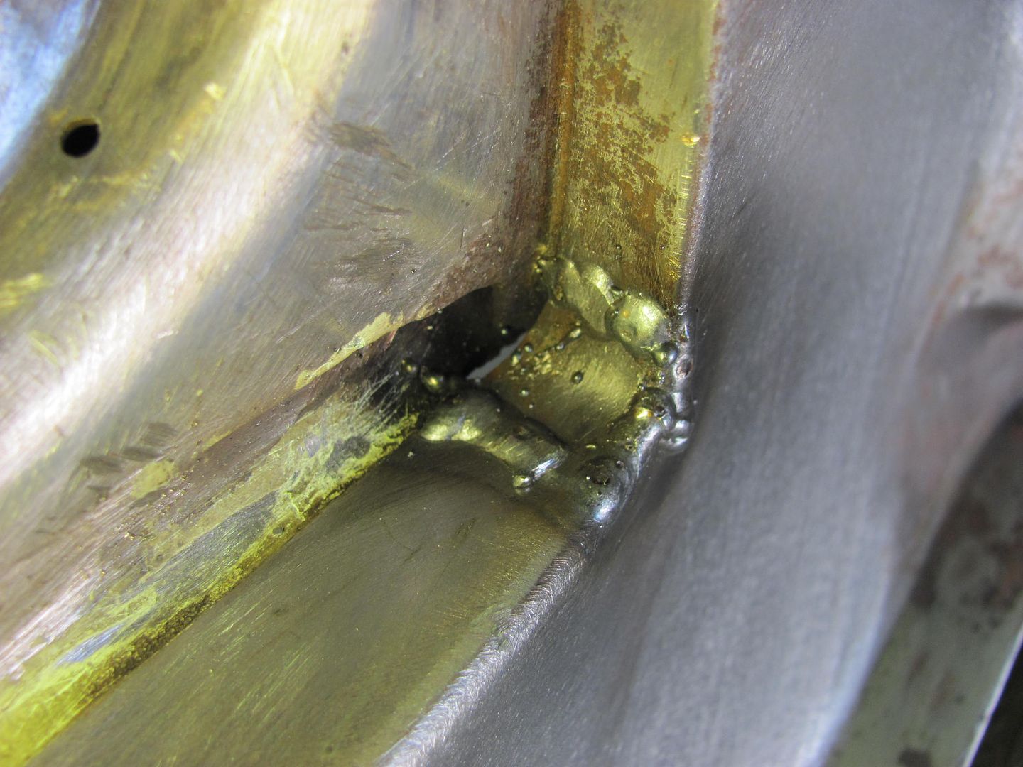
Fitted, welded, and looking much better!

Thought I'd spend some time this evening to see how I could clean up these corners....
Trimming out some of the excess...
Used the roll former die to make the radius....
Fitted, welded, and looking much better!
Kevin54
MEMBER EMERITUS
Robert......Can you show a larger pic of the punch and die shown above? The reason I ask is that in another thread it was discussed about a roll form die, and I mentioned about making a universal punch like you show above. Outside of shop, that is the first I have saw someone else using one.
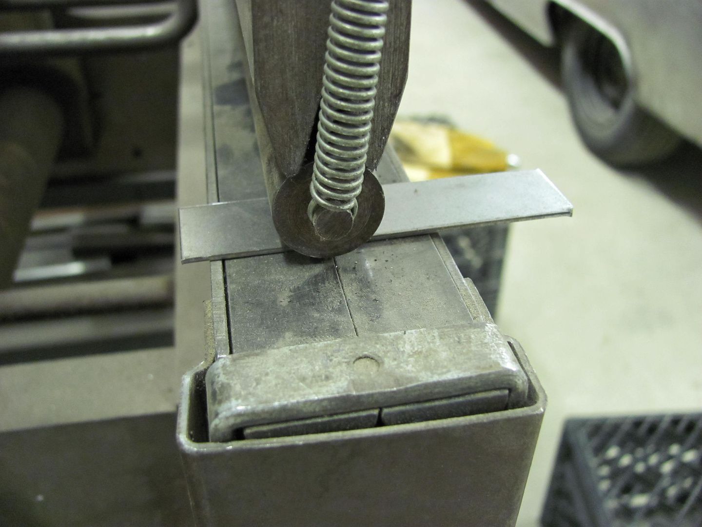
Kevin, here you go. I had never heard of the roll-former die until I won the auction for the press brake that had one. This should show the theory for anyone else who has not seen one....

Looking at the upper die, it is an acute lower die that has been (factory??) modified with the addition of an "extension kit". You can see in the following pictures that the radius can easily be changed by using a different rod. (My brake with this die came out of a trophy shop in NJ....so one can surmise they were using it on lighter guage aluminum)


The lower die consists of two half shafts that rest on a machined bed. The "clips" at the end keep the shafts together, it is spring loaded to keep them flat while not in use.


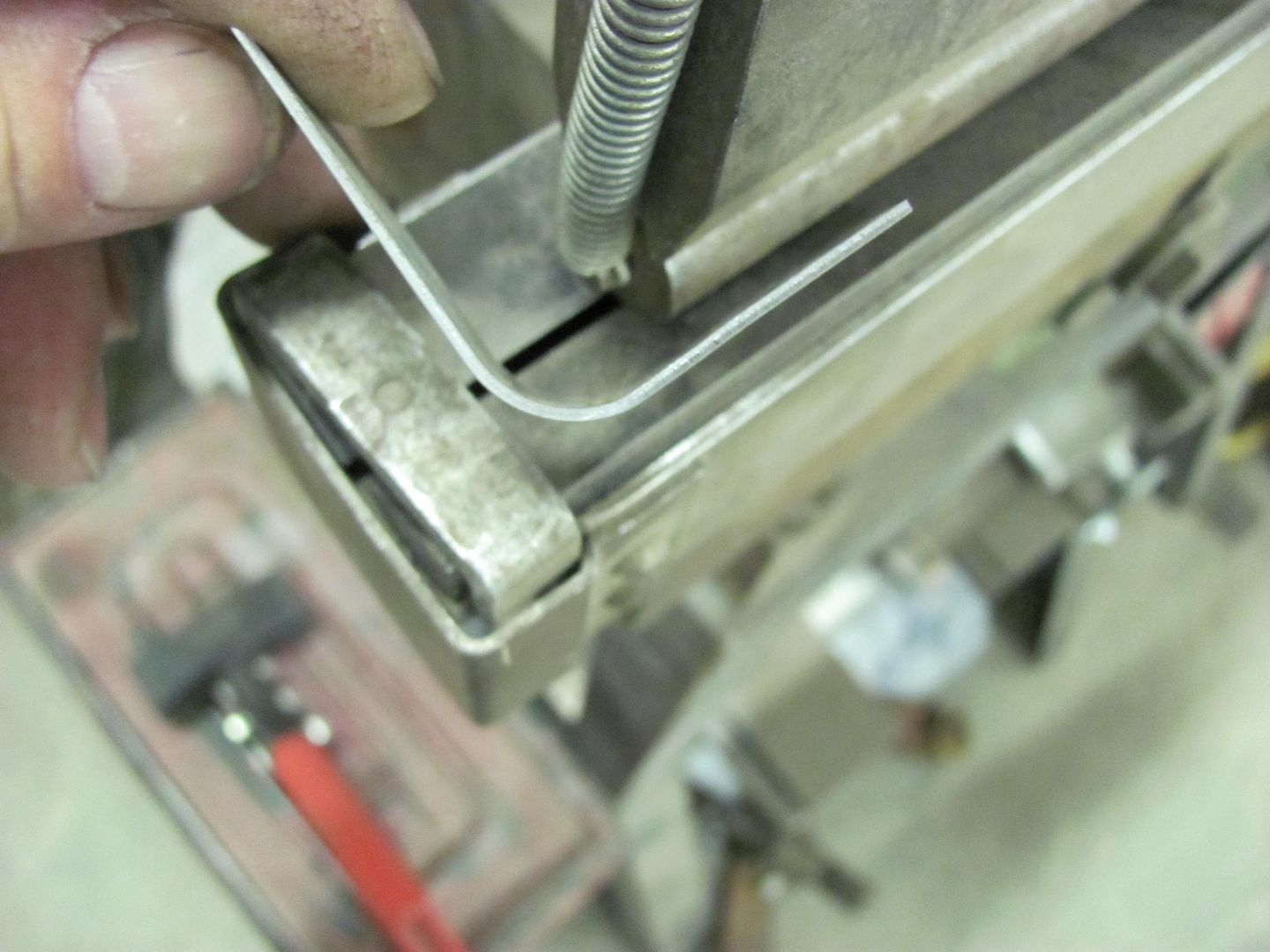
And as is seen in the next pictures, the theory is for the lower shafts to rotate around the top die, for hopefully less die marking of the work piece. May be why this was in a trophy shop.


Looking at the upper die, it is an acute lower die that has been (factory??) modified with the addition of an "extension kit". You can see in the following pictures that the radius can easily be changed by using a different rod. (My brake with this die came out of a trophy shop in NJ....so one can surmise they were using it on lighter guage aluminum)
The lower die consists of two half shafts that rest on a machined bed. The "clips" at the end keep the shafts together, it is spring loaded to keep them flat while not in use.
And as is seen in the next pictures, the theory is for the lower shafts to rotate around the top die, for hopefully less die marking of the work piece. May be why this was in a trophy shop.
That roll former die is really cool, I've made radius parts like that on a press brake by using a piece of polished round stock for the upper die and a wide lower v die on the bottom. We had thin urethane sheets to place on the lower die to prevent tool marks. It was always was a **** shoot as to what the radius turned out to be.
Kevin54
MEMBER EMERITUS
That roll former die is really cool, I've made radius parts like that on a press brake by using a piece of polished round stock for the upper die and a wide lower v die on the bottom. We had thin urethane sheets to place on the lower die to prevent tool marks. It was always was a **** shoot as to what the radius turned out to be.
A vee die also works, but what is nice about the top punch is that you can change the rods out and make any radius you want. The only reason for the vee in the top punch is to keep the rod from moving and to keep it centered. One punch saves al lot of money as all you have to do is buy some different sizes of round stock to suit your needs.
The roller die is the cat's *** per se, but the roller die is considerably more expensive to buy and it takes a little mare to make one than a Vee die. I'm not sure of the punch and die company right at the moment, but I want to say Accurite. They make a real nice 4 way Vee die that is square, but each side is a different size Vee. It's made from aluminum and has a hard coat anodize on it. Plus you can cut it to modify to fit your needs.
Thanks Robert for taking the time to post the pictures up. I appreciate it as I know other will also.

alpinewhite
Well-known member
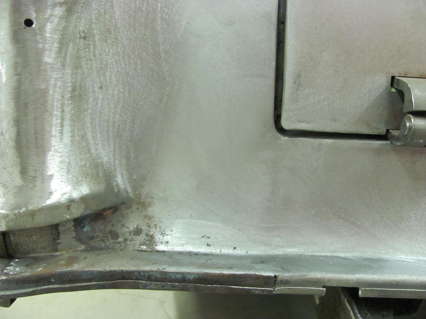
Great work!!!! Keep the pictures coming.Welds dressed
Kevin54
MEMBER EMERITUS
Robert......when you are all done with the car, do you make up a notebook showing all the work that has been done on the car? You have showed a shitload of pics on here with explanations as to the process done. Does the owner get the same privilege of having a photo history of all of the simple little repairs that has taken countless hours if you add them up?
Just like the above pictures of the repairs, if you didn't point it out, not one single person would look at it and ever know what it took to fix it. I'd say that 95% of people that have a car repaired from someone other than their self, don't realize what it takes to do something. They only look at the overall picture and not the details. When I go to car shows with the wife, I often point out small things to the wife. It may be something as simple as the bolt heads all clocked the same direction. Something that most wouldn't look at or give a second thought to, but the owner, or whoever, took the time and the care to do it.
I know that when the owner gets their car back from you, they would really appreciate seeing what we see on here.
Omphaloskeptic
Well-known member
I have to add to Kevin54's thought with my own....
If the customer sat down and looked through a thread here on the work done to their vehicle, they would/should be THRILLED to write that final check!
If the customer sat down and looked through a thread here on the work done to their vehicle, they would/should be THRILLED to write that final check!
Where most of my customers have been local, I have had the occasional customer 45 minutes and even up to two hours away. The online progress posts have come in handy to show the owner where we are, and especially to show the detail work that has been done. The photobucket albums on this wagon alone are up to over 2600 pictures.
alpinewhite
Well-known member
What's the rarest car you've ever restored?
Probably the 1951 Triumph Saloon, but I didn't get a chance to finish it. The owner was an elderly gent who came down with abdominal cancer, and went downhill quickly. His son didn't want to continue the restoration, so it was sold as a project.
The last one I finished before this wagon was a 65 Fairlane, which in itself isn't too rare, but finding parts is. Here's the thread on it....
http://www.garagejournal.com/forum/showthread.php?t=86935
The last one I finished before this wagon was a 65 Fairlane, which in itself isn't too rare, but finding parts is. Here's the thread on it....
http://www.garagejournal.com/forum/showthread.php?t=86935
Last edited:
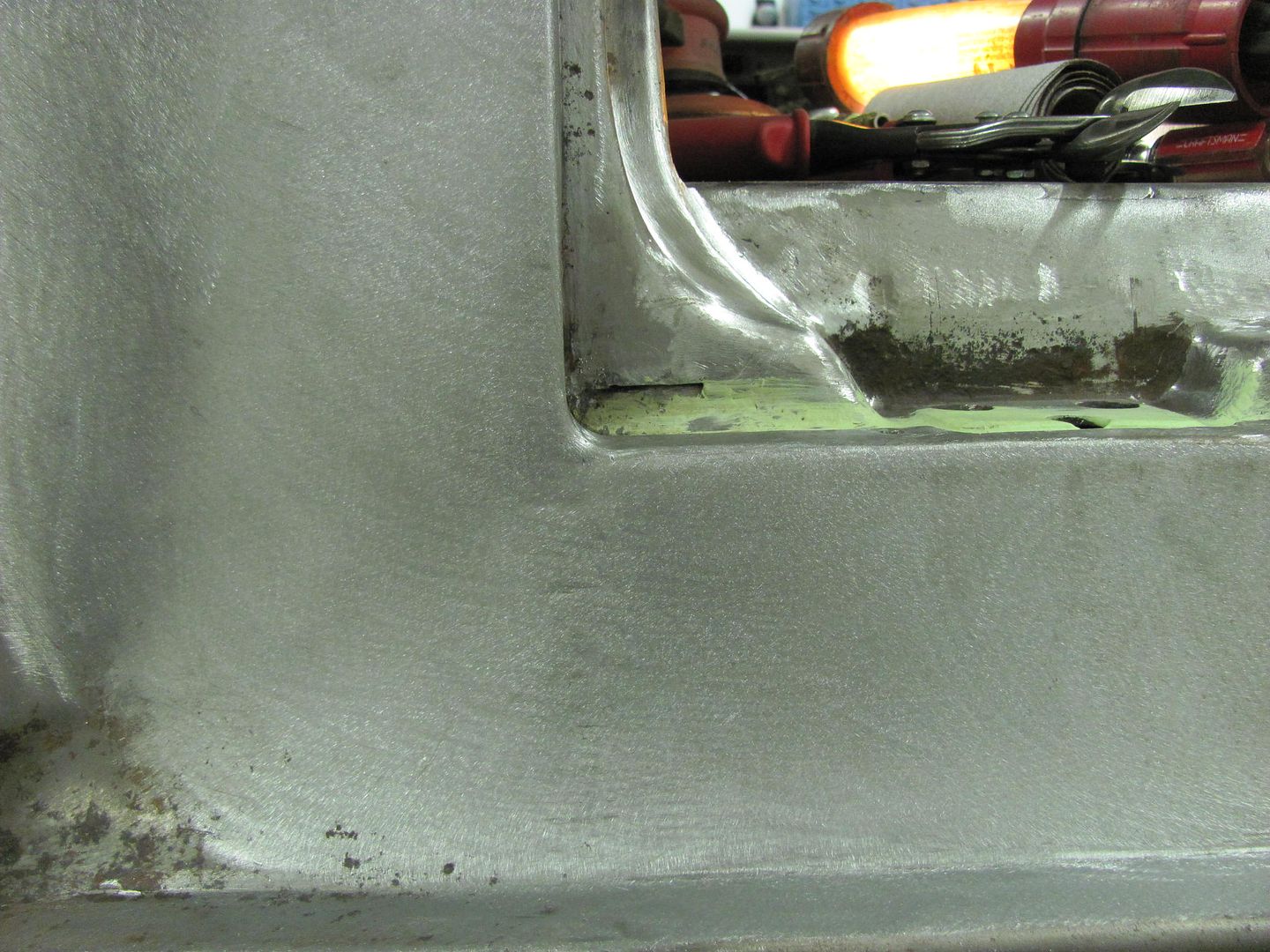
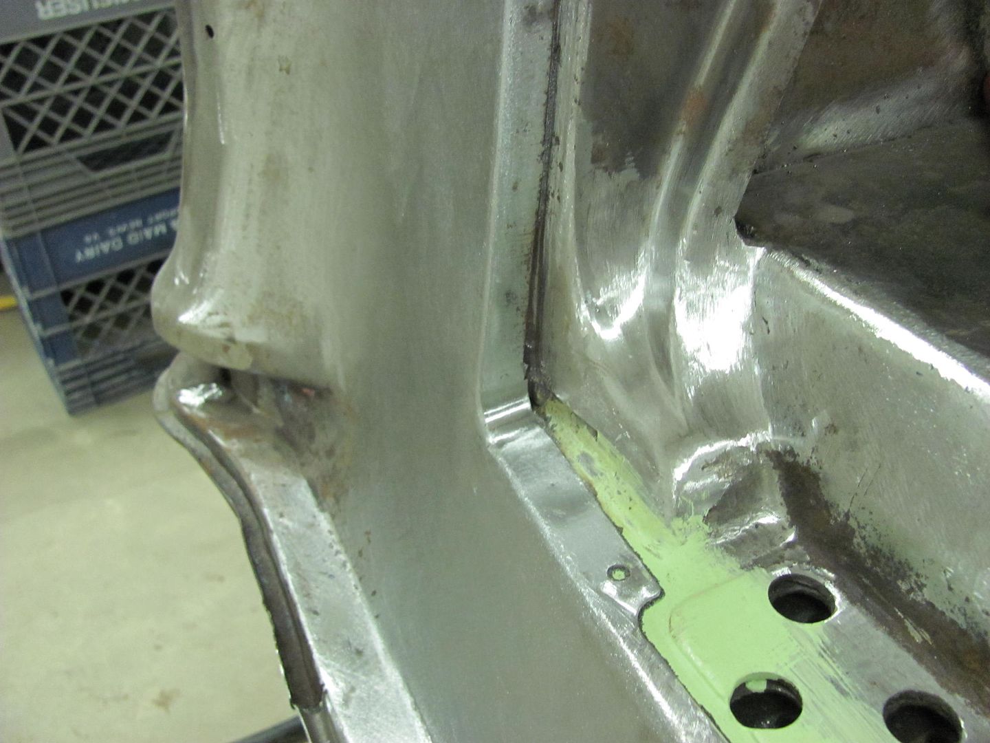
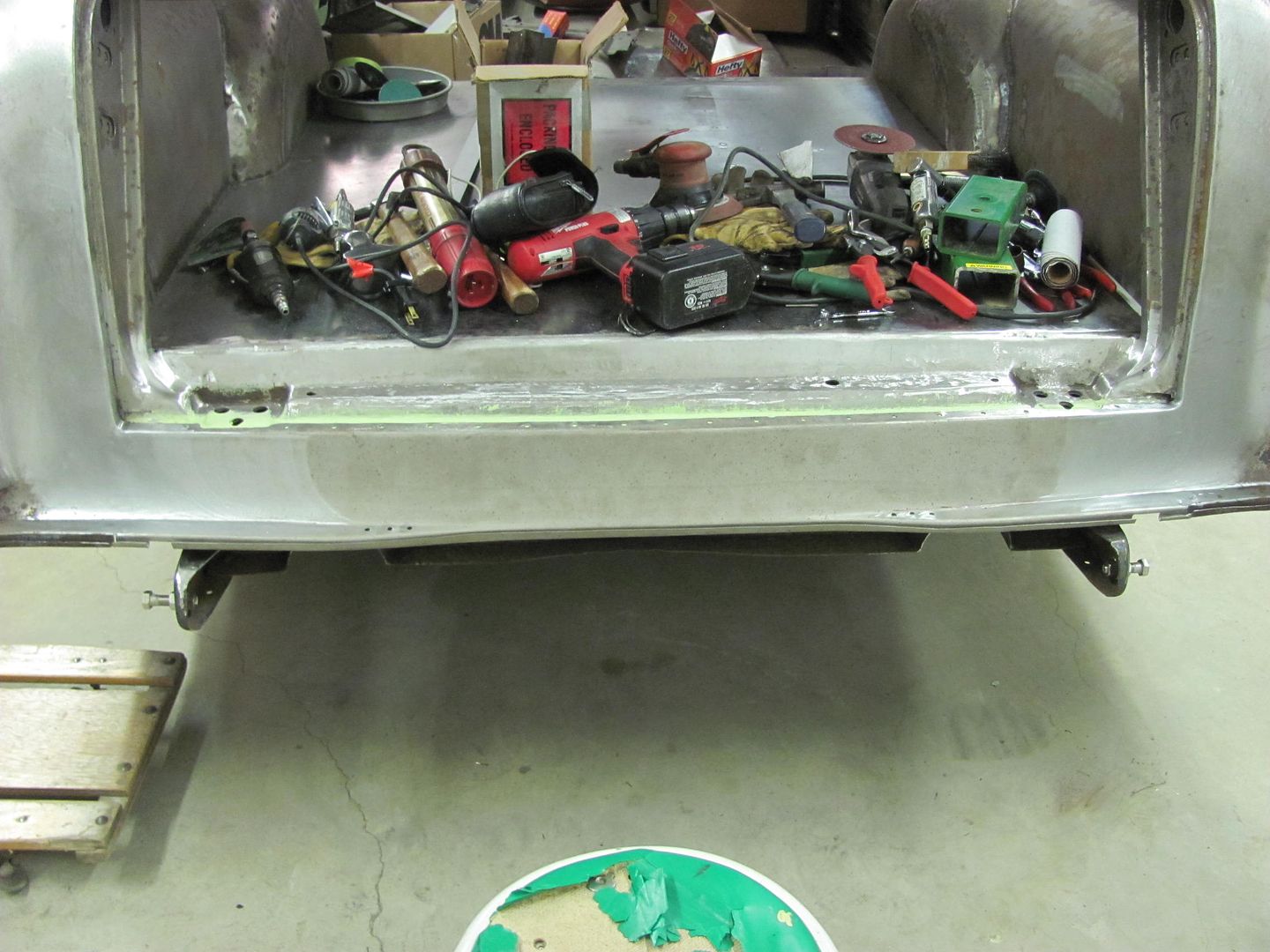
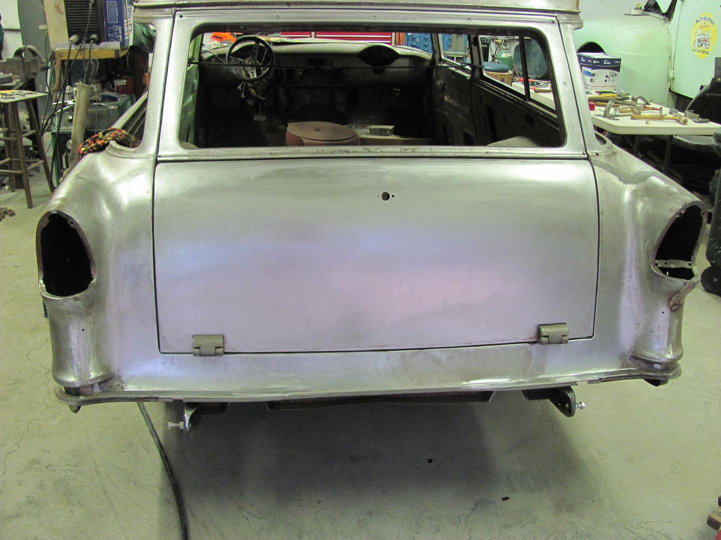
Not too much shop time this weekend, but I did manage to test fit the tailgate to see how well it matched the new radiuses added to the opening.
There are a couple areas the gaps will need tweaking, but the "new" corners should help add to the other subtle changes.
There are a couple areas the gaps will need tweaking, but the "new" corners should help add to the other subtle changes.
Last edited:
19richie66
Member
- Joined
- May 13, 2012
- Messages
- 7
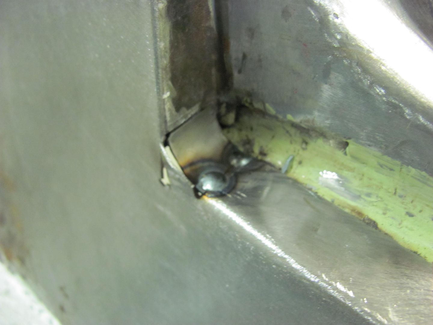
Much better. As far as the cleanup in the tight areas, do you just use a die grinder with a rotary cutting bit? Looks great though. Thanks for all of your "lessons". Its appreciated. Love the Fairlane build also.
Where I normally use a cutoff wheel to knock down the proud of the weld and a roloc sanding disc to finish, this corner is much too tight for that, so the majority of the weld is removed with a carbide burr in the die grinder, then switched to a 3/4" dia sanding drum on the die grinder.


e-tek
Well-known member
More AWESOME work Robert. I spend a lot of time looking at your detail-work because that's (one of the) major differences between you and I. You have an incredible attention to detail and finesse for those details that I need to continue to develop. Maybe I spent too much time in a production shop, maybe it's a personality thing - but it definitely comes through in your posts!
Not many guys would spend the time to make athe perfect tool as above. Most (me included!) would just use a pair of pliers, maybe wrapped in tape... Could be a side-line for you if you could just figure a way to produce numbers of them.
Cheers to the MASTER!
(Also wish I could go to some of these MetalMeets!)
Last edited:
Ed, thanks for the feed back. I guess what drives the attention to detail the most is not being satisfied that the method you used last time is the only way, or the best way. By striving to improve over the last method, it tends to open the doors to new processes. Where the results may not be best for exactly what you're doing at the moment, the experience and outcome (whether good or bad) has normally served to spark another idea whenever a new challenge presents itself.
Omphaloskeptic
Well-known member
MP&C, I really like your attitude; one that I can aspire to. Not only is your glass always half-full, you're willing to make the glass!
Thanks!
Previous work on the wagon included making this window opening stiffener.....

Noticeable rot in was the stiffener brace along the window opening.

...and from the underside..

As this also helps to strengthen the quarter across the opening, this is another candidate for repair. Here's the newly formed replacement.


Here it is test fit into place.

I received a recent PM about making a set of these for a sedan delivery to windowed conversion. These braces are only used in the 2 door windowed wagon. I worked on these this evening, didn't get much for in process pictures, but here are the new parts all ready:


For alignment when installing, the front edge is lined up with the window opening, and then checked to the slots..


Previous work on the wagon included making this window opening stiffener.....
Noticeable rot in was the stiffener brace along the window opening.
...and from the underside..
As this also helps to strengthen the quarter across the opening, this is another candidate for repair. Here's the newly formed replacement.
Here it is test fit into place.
I received a recent PM about making a set of these for a sedan delivery to windowed conversion. These braces are only used in the 2 door windowed wagon. I worked on these this evening, didn't get much for in process pictures, but here are the new parts all ready:
For alignment when installing, the front edge is lined up with the window opening, and then checked to the slots..
Kevin54
MEMBER EMERITUS
Nows the time to open those wheel openings up to the Nomad style
Kevin, that's an old picture, quarter is already closed up now....
Today I worked on part of the HDL, we have a canoe that has been stored in a car trailer, and to make it more accessible, and easier to load on top of the wife's SUV, it will get stored here, above the door tracks....

Most of what I found online in canoe hoists looked "lightly" made at best. Plus, I needed to take the ropes to a side wall for securing, which meant no "kit" was complete for what I wanted. I checked a couple different local stores today, and about the cheapest pulleys I could find (with bearings) were ones designed for patio doors. Here they are installed in the 16 ga Stainless brackets I bent up....


Using one for each end, then changing direction mid-stream to take the rope over to the side wall, using this bracket....


Tomorrow I'll make the ceiling to wall transition bracket, and the pulley/hook brackets to support the ends of the canoe.
Today I worked on part of the HDL, we have a canoe that has been stored in a car trailer, and to make it more accessible, and easier to load on top of the wife's SUV, it will get stored here, above the door tracks....
Most of what I found online in canoe hoists looked "lightly" made at best. Plus, I needed to take the ropes to a side wall for securing, which meant no "kit" was complete for what I wanted. I checked a couple different local stores today, and about the cheapest pulleys I could find (with bearings) were ones designed for patio doors. Here they are installed in the 16 ga Stainless brackets I bent up....
Using one for each end, then changing direction mid-stream to take the rope over to the side wall, using this bracket....
Tomorrow I'll make the ceiling to wall transition bracket, and the pulley/hook brackets to support the ends of the canoe.
Last edited:
Finishing up the brackets, here's the ceiling to wall transition, this one was made in 3 pieces and fusion welded together..


Then to make the pulley hooks for the canoe straps...


Installed, and using a crossbrace from the scaffolding for a dry test run...


All the bits installed....


Then to make the pulley hooks for the canoe straps...
Installed, and using a crossbrace from the scaffolding for a dry test run...
All the bits installed....
Omphaloskeptic
Well-known member
Robert, very nice piece of fabrication (and very handy too)!
Since you use this rig for a canoe, you might find this a (safety) device to add on (or build) to mount above the tie-off cleat.
http://dieballstore.com/harken-ball-bearing-cam-matic-cleats.html#.UaEk4sq8PwU
Since you use this rig for a canoe, you might find this a (safety) device to add on (or build) to mount above the tie-off cleat.
http://dieballstore.com/harken-ball-bearing-cam-matic-cleats.html#.UaEk4sq8PwU


Well now that the canoe is out of the trailer, I was able to paint the inside walls today and put it on the street..

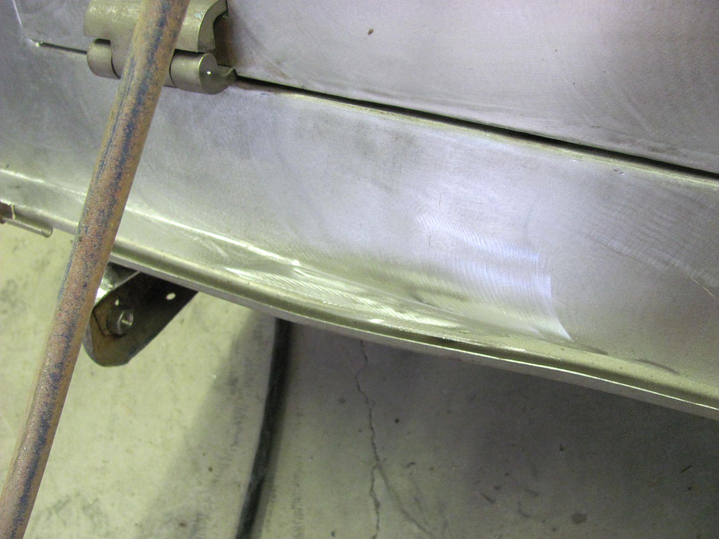
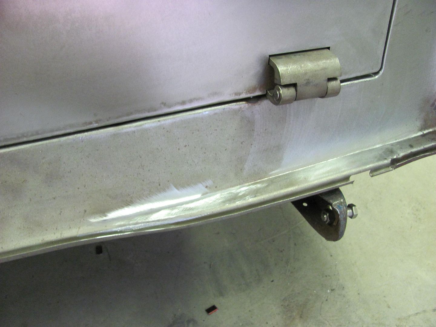
And found a bit of time for the wagon, working on some of the plug welds for the rear valance....
The ones at the bottom attach to two braces underneath, and fitted the tailgate to pull in the valance to match the bottom of the tailgate...

And found a bit of time for the wagon, working on some of the plug welds for the rear valance....
The ones at the bottom attach to two braces underneath, and fitted the tailgate to pull in the valance to match the bottom of the tailgate...
Omphaloskeptic
Well-known member
That tail looks so good it's almost a pity to hide any of it behind a bumper!
e-tek
Well-known member
Do you ever get any flash-rust on all that bare metal? Must be dryer than I thought in MD!