
You are using an out of date browser. It may not display this or other websites correctly.
You should upgrade or use an alternative browser.
You should upgrade or use an alternative browser.
MP&C Shop Projects
- Thread starter MP&C
- Start date
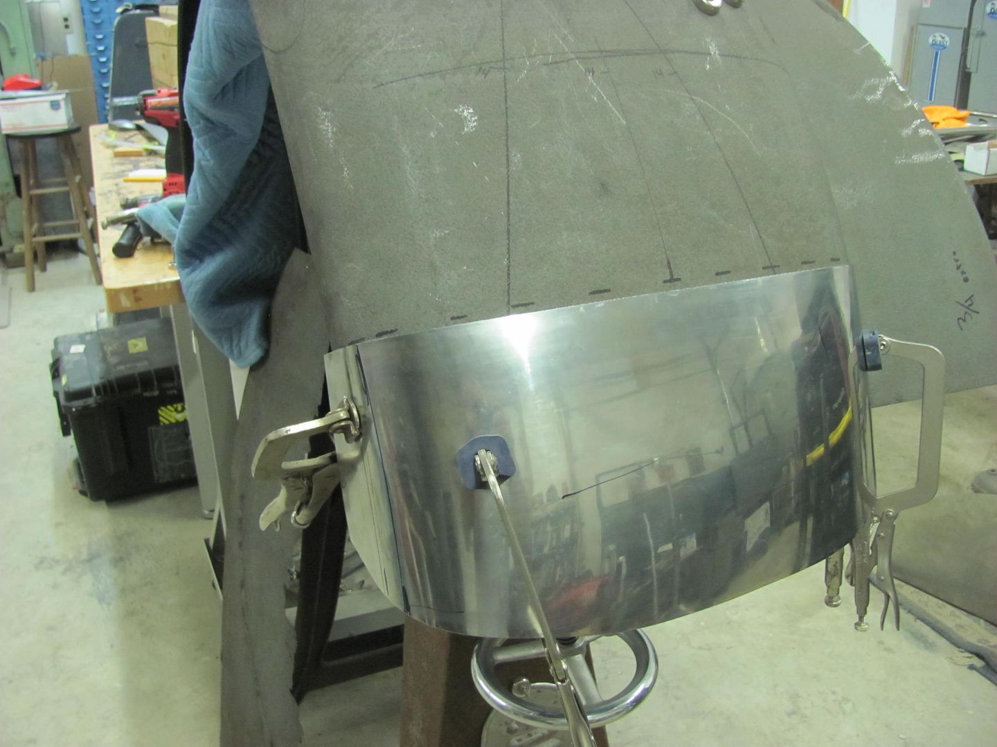
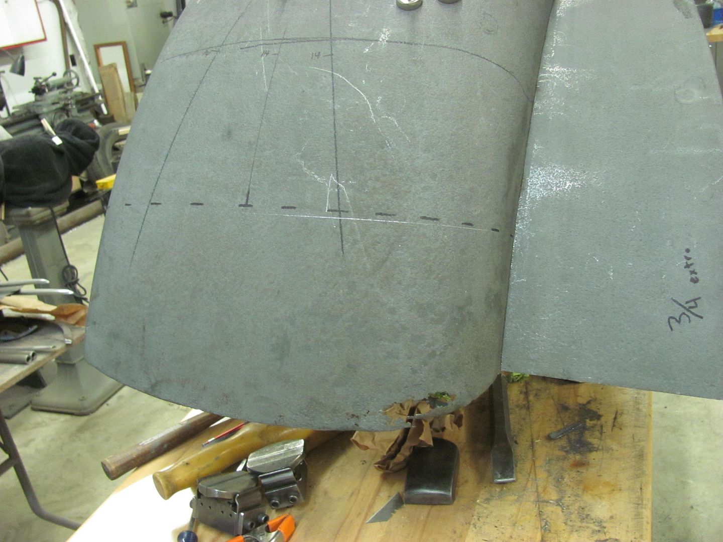
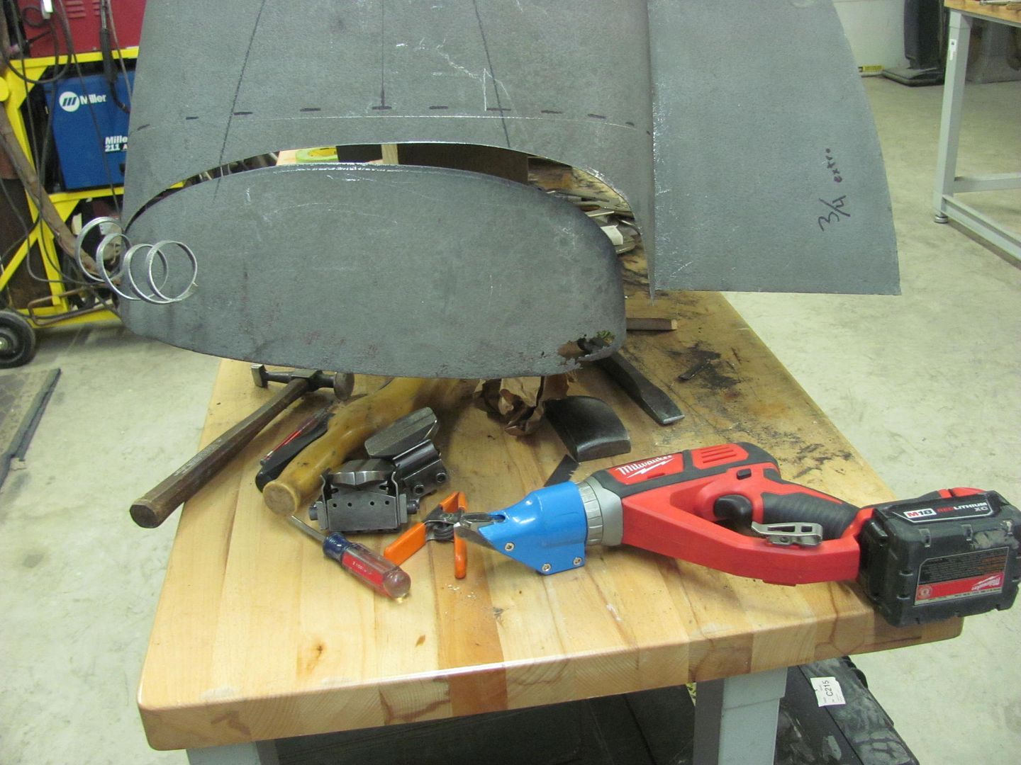
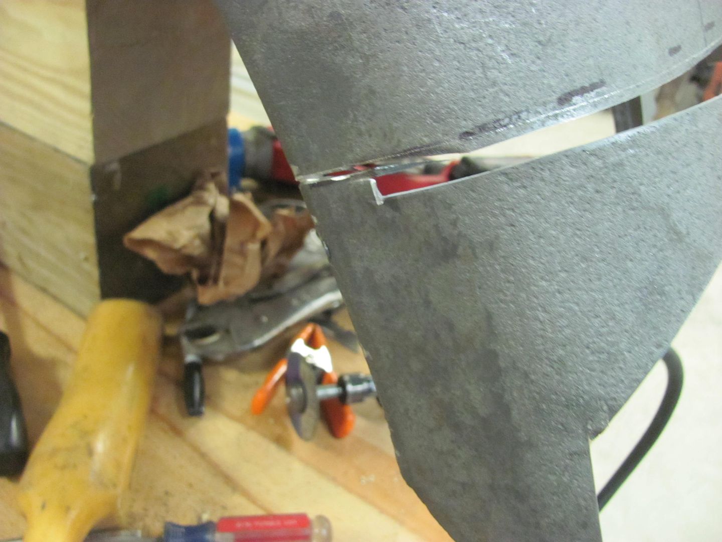
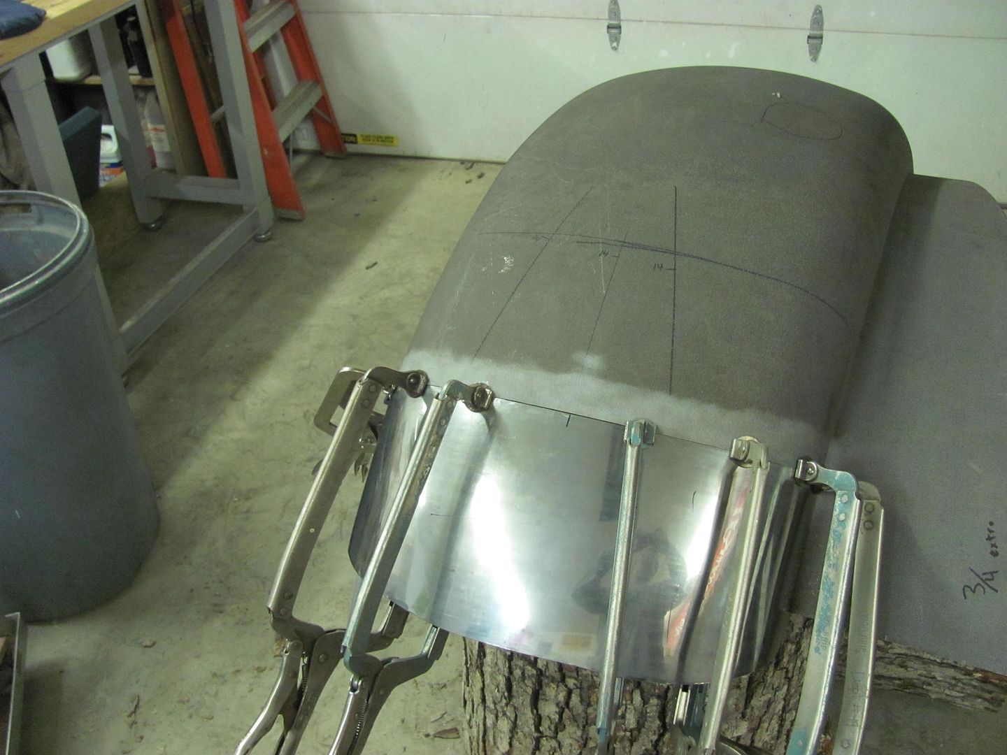
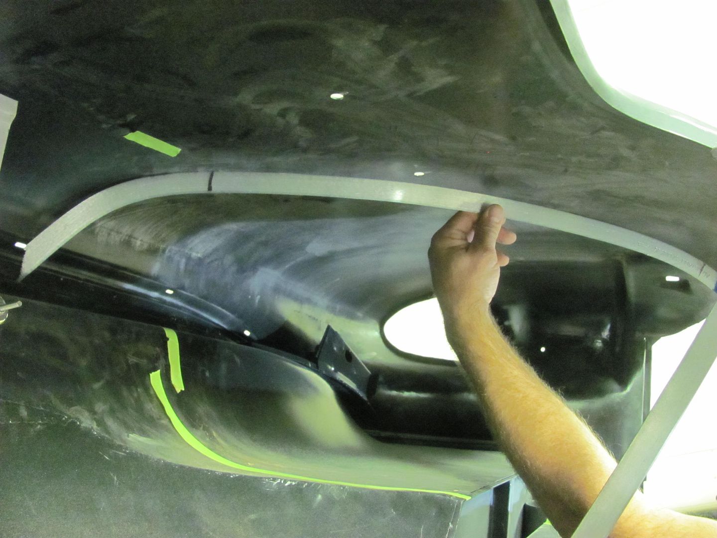
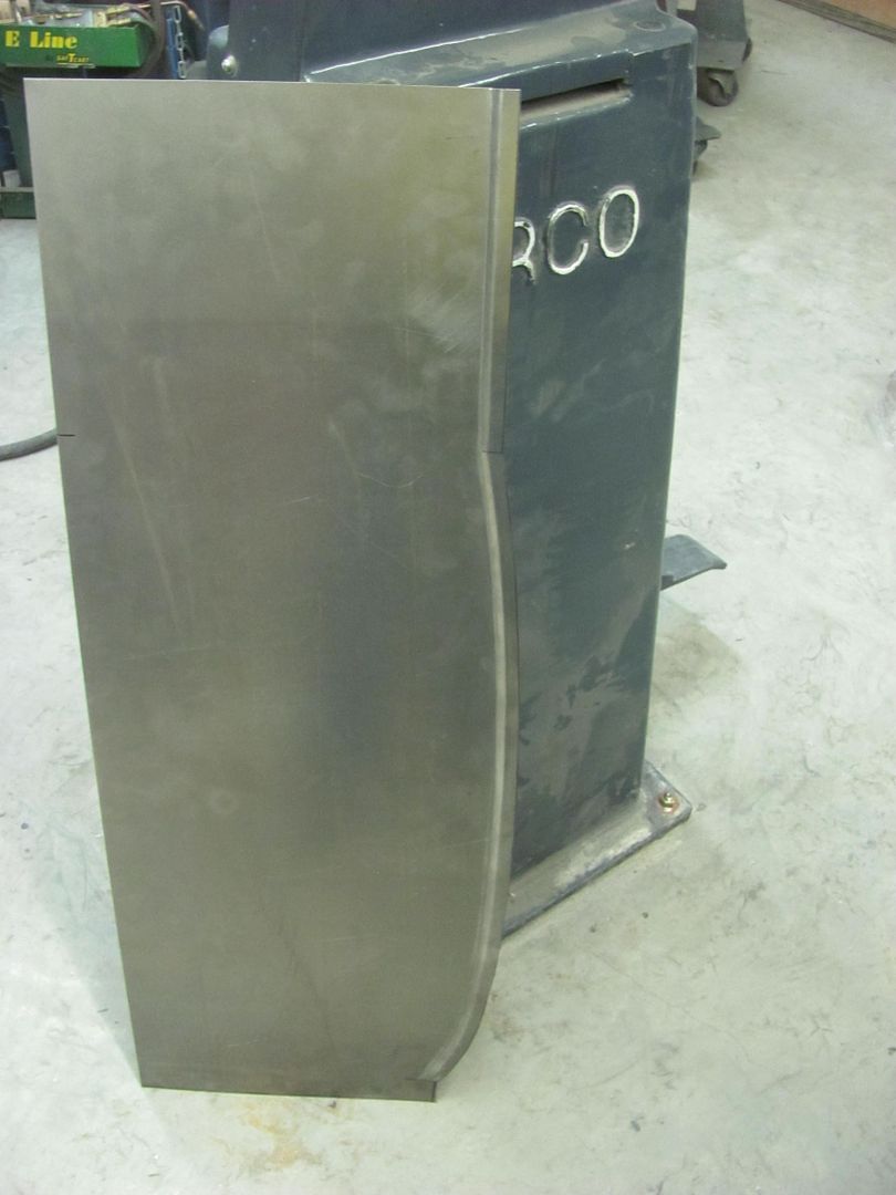
Final tweaks ..... clamped and marked with a scribe..
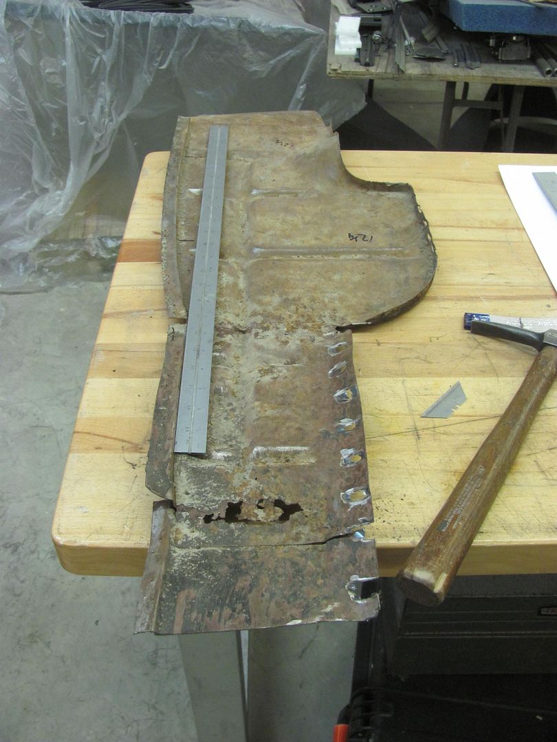
Trimming out the rust...
14 ga rated Milwaukee shear walks right through...
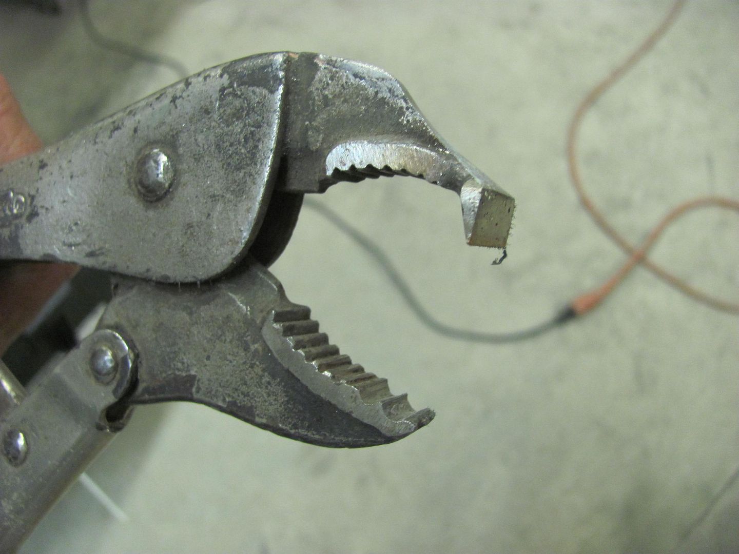
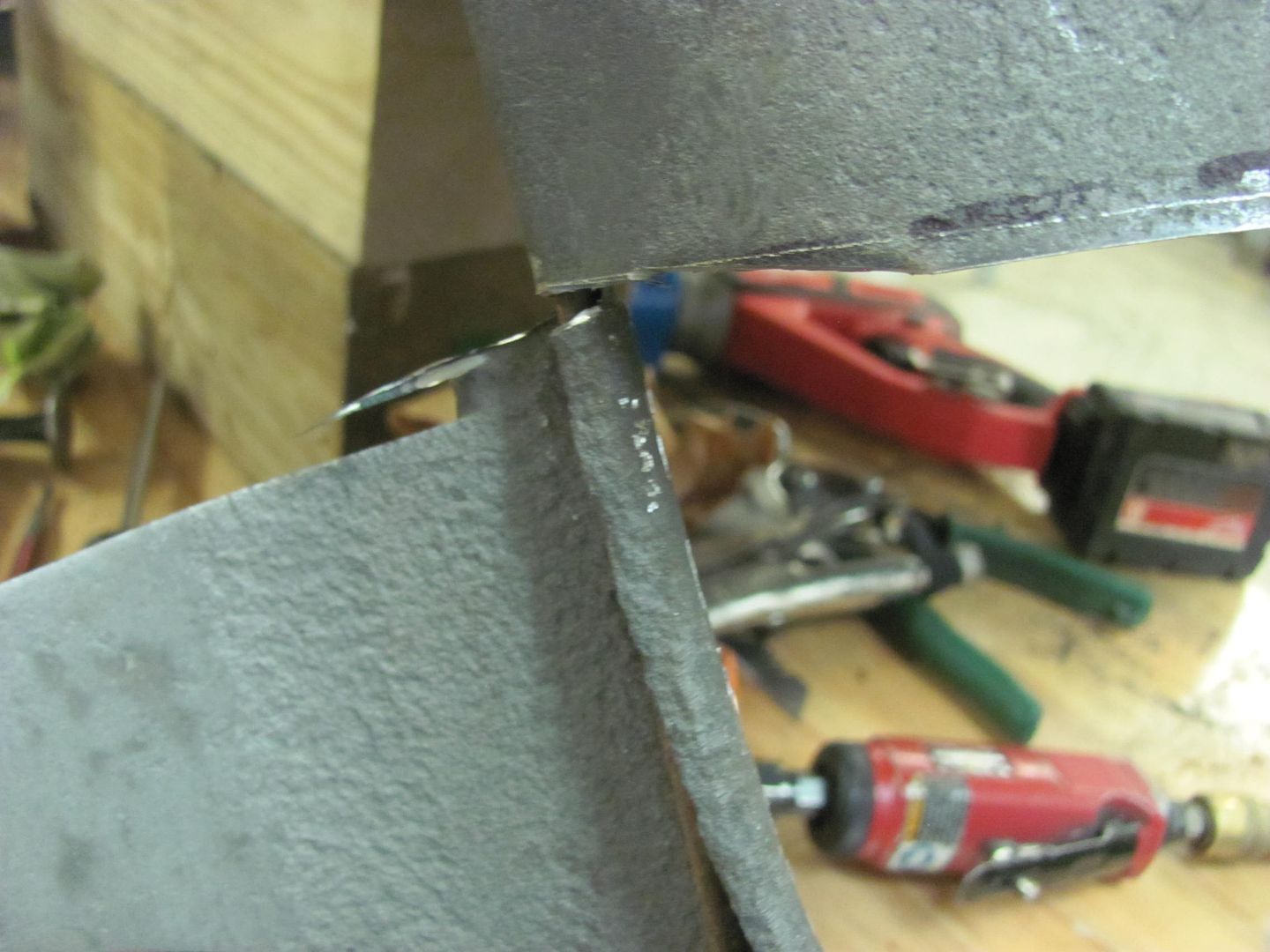
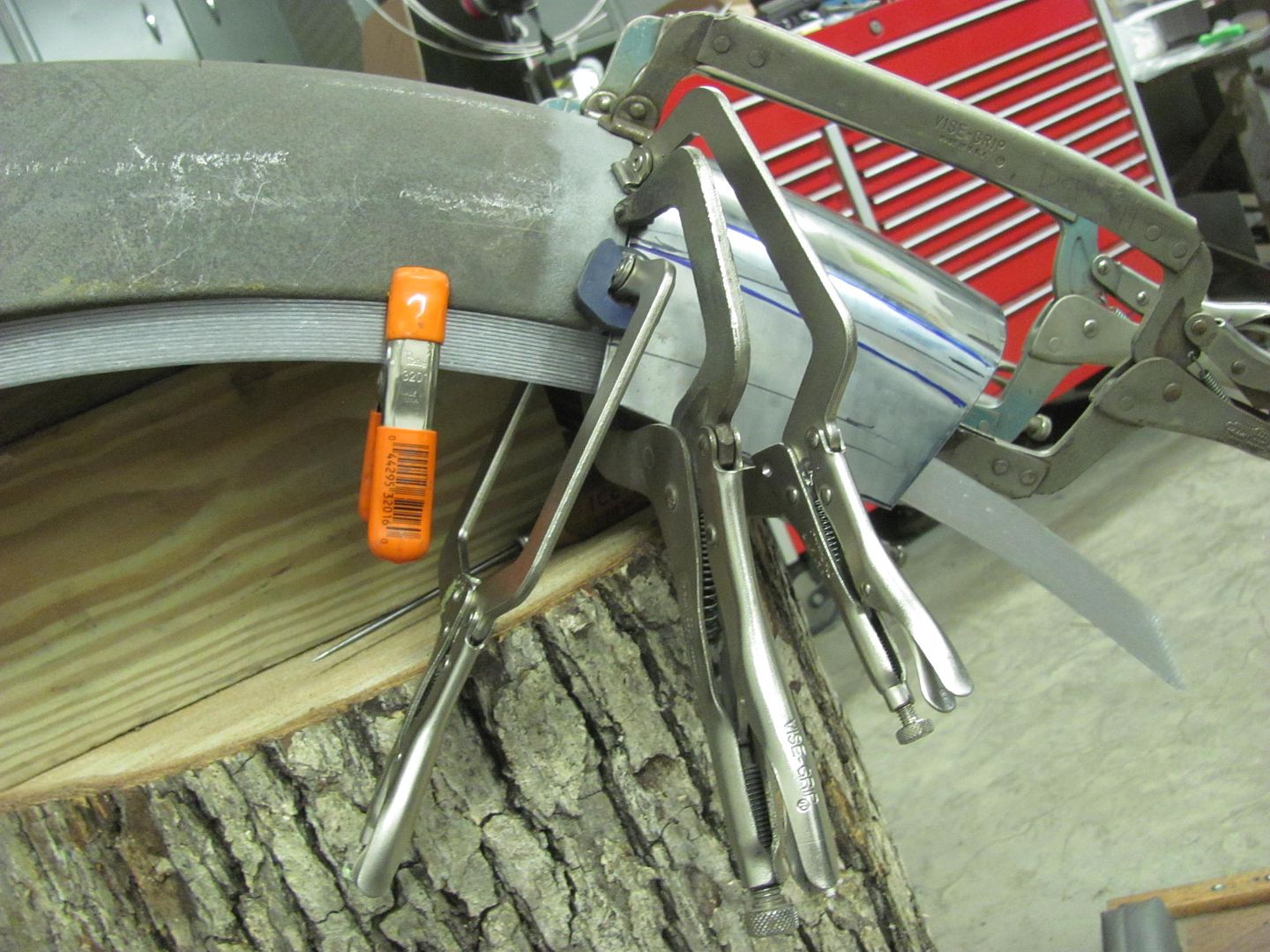
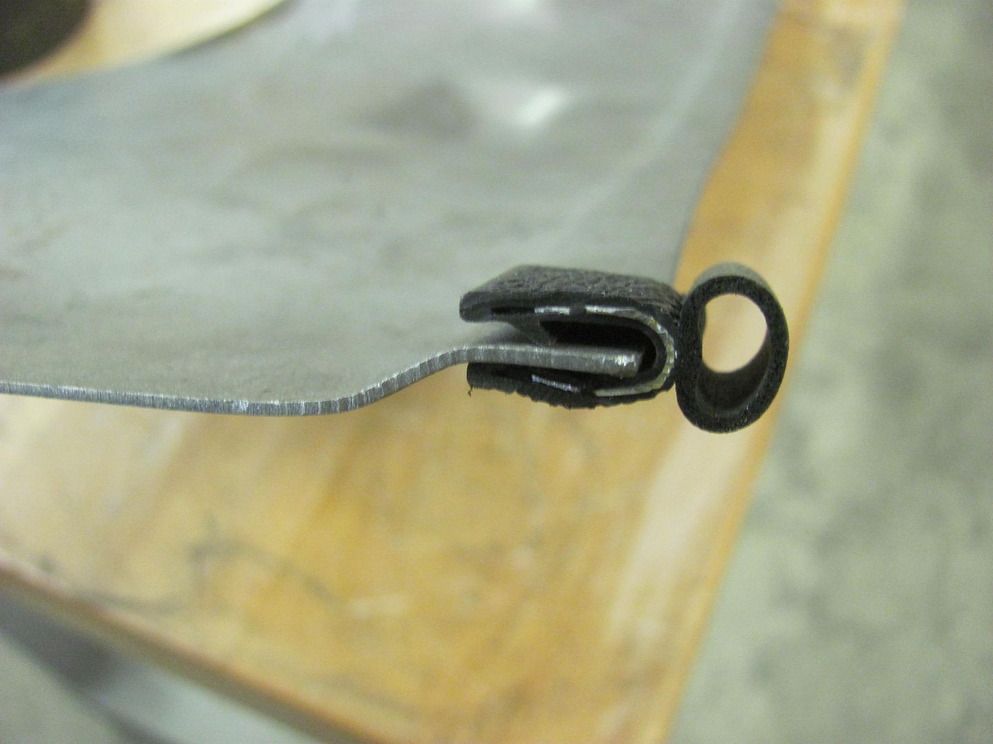
Trimming around the wired edging, careful not to nick it. The wrapped sheet metal is opened slightly using the door skin pliers..
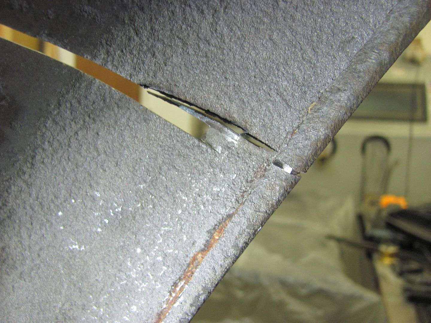
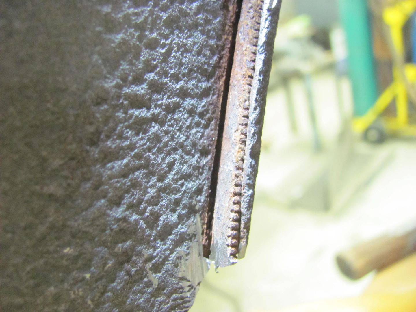
With the sheet metal loosened from the wire, a slight twist will break the sheet metal at the score even not having cut through to the wire.
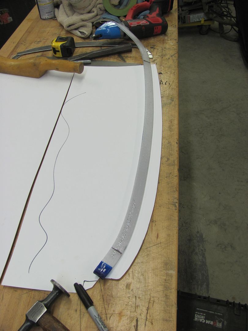
This outer section will become a template for the radius on the new patch.
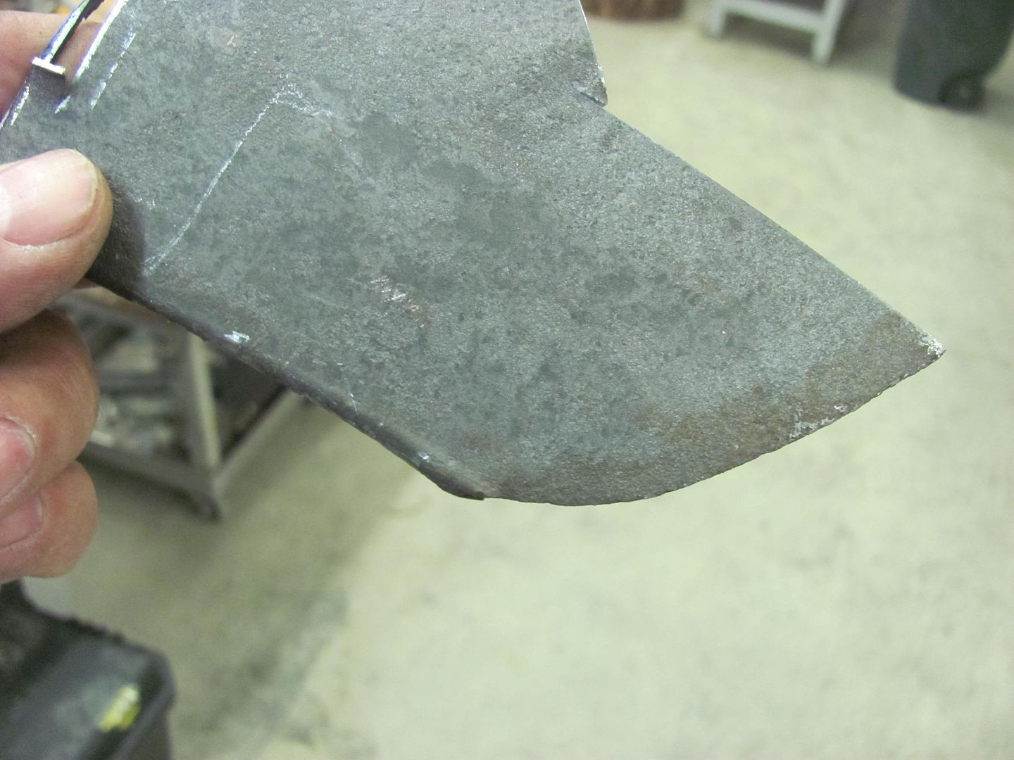
Trimmed....
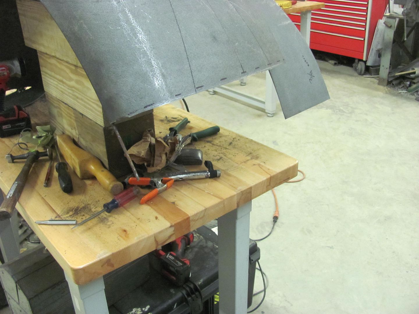
Fitted....
Saturday Kyle will get the old metal media blasted next to the weld seam so we can fire up the TIG welder..
Trimming out the rust...
14 ga rated Milwaukee shear walks right through...
Trimming around the wired edging, careful not to nick it. The wrapped sheet metal is opened slightly using the door skin pliers..
With the sheet metal loosened from the wire, a slight twist will break the sheet metal at the score even not having cut through to the wire.
This outer section will become a template for the radius on the new patch.
Trimmed....
Fitted....
Saturday Kyle will get the old metal media blasted next to the weld seam so we can fire up the TIG welder..
Last edited:
Kirkski
Well-known member
Robert, Great work!
Concerning my welding, when I started my project I had no welding experience with MIG. I thought all of the issues I was having was me and my technique. I tried to mimic your work with no success.
Turns out after burning through a 2 lb roll of wire that my boss got me from "Advanced Auto Parts" my welds looked no better, had little penetration and I had to grind my backside off to make them look decent..
Well after using an entire spool of wire, I went to a local welding supply house and I picked up a new roll of the same spec wire size, grade etc... and what a difference it made..
Beautiful welds, nice penetration, no holes in them and easy clean up... Boy did I learn a valuable lesson... Don't buy crappy wire...
My welds look as good as... well I'm trying to make my fits look like yours!
Thanks again for all the information you freely give out, I appreciate it!
Kevin54
MEMBER EMERITUS
Am I looking at things wrong, or does the head of the shear rotate 90 degrees?
Robert, Great work!
Concerning my welding, when I started my project I had no welding experience with MIG. I thought all of the issues I was having was me and my technique. I tried to mimic your work with no success.
Turns out after burning through a 2 lb roll of wire that my boss got me from "Advanced Auto Parts" my welds looked no better, had little penetration and I had to grind my backside off to make them look decent..
Well after using an entire spool of wire, I went to a local welding supply house and I picked up a new roll of the same spec wire size, grade etc... and what a difference it made..
Beautiful welds, nice penetration, no holes in them and easy clean up... Boy did I learn a valuable lesson... Don't buy crappy wire...
My welds look as good as... well I'm trying to make my fits look like yours!
Thanks again for all the information you freely give out, I appreciate it!
Glad it worked out for you!
Am I looking at things wrong, or does the head of the shear rotate 90 degrees?
Kevin, it has a spring loaded tab that locks into a detent, the head swivels and locks at 45* increments.
Today was more blocking on the 55, and moving forward to get it ready for the Linex that will go on the bottom side. We need to get seat brackets complete and welded into the floor, finish epoxy prime on cavities (rocker and inner quarter), install wheel houses, etc. Yesterday was a road trip to get a paint sample and other paint supplies. here's the proposed color for above the quarter...
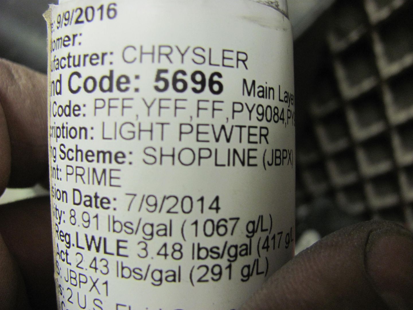
With the H/K Organic Green Kandy basecoat on the quarters down. To better get a feel for the test sprayout of the Kandy, a panel was made to simulate the top of the quarter, so we can better see the effects in the sunlight...
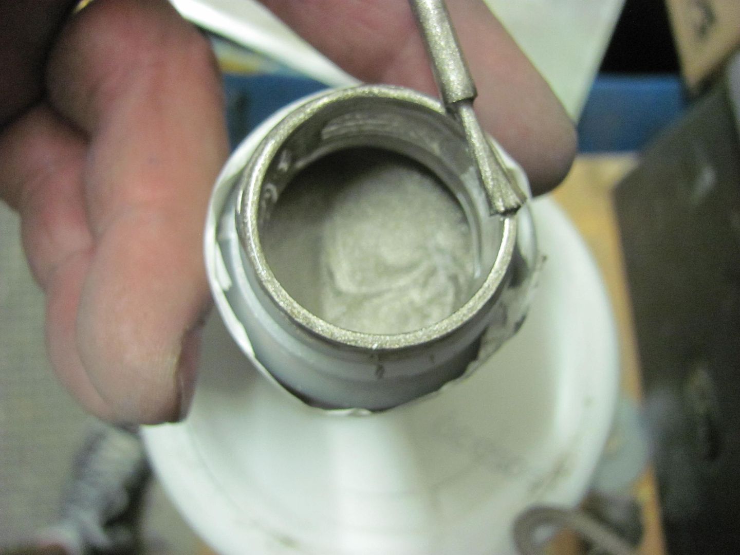
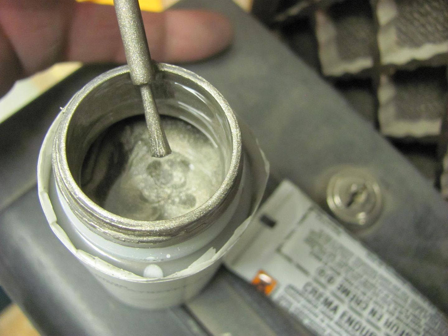
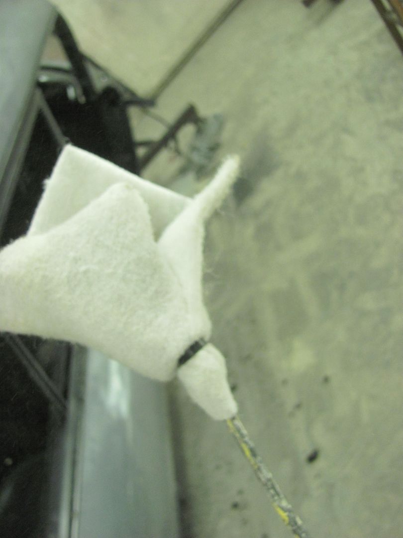
Next, epoxy in the cavities. I had looked at cavity spraying wands and the like, and did not care for what was available. So lets get basic, after all it is unseen when complete..
This area doesn't have to be pretty, so picked up this goodie at the local hardware store..
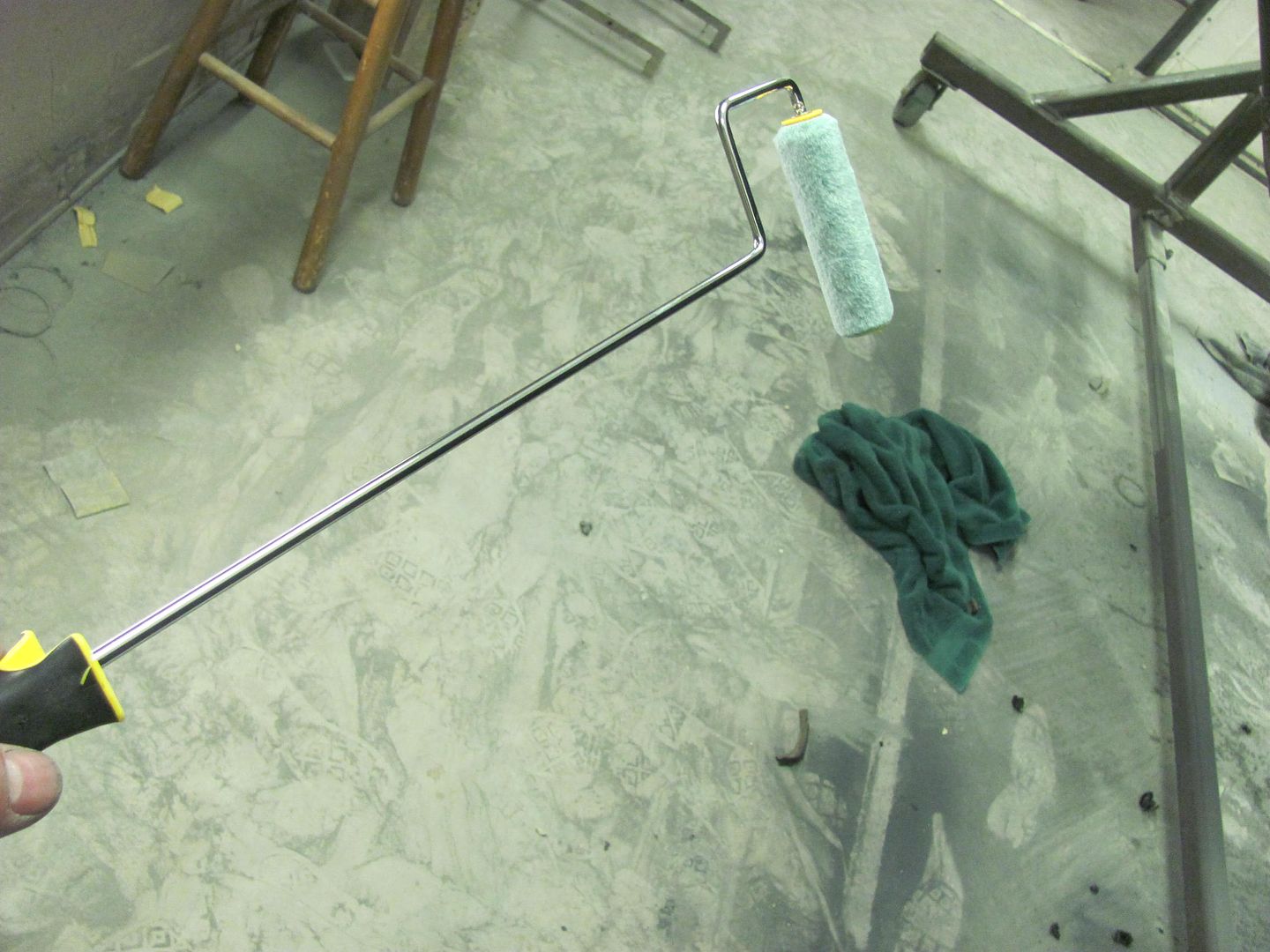
.....which should get enough on the inner quarter to seal things up..
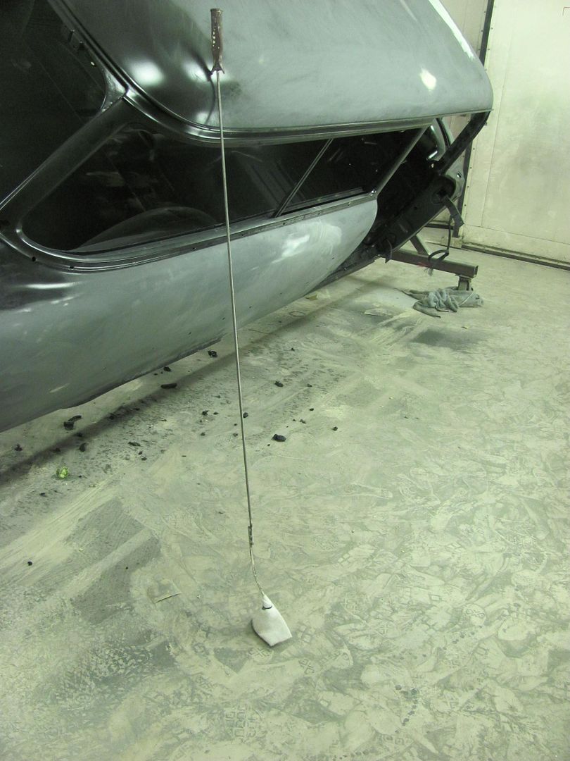
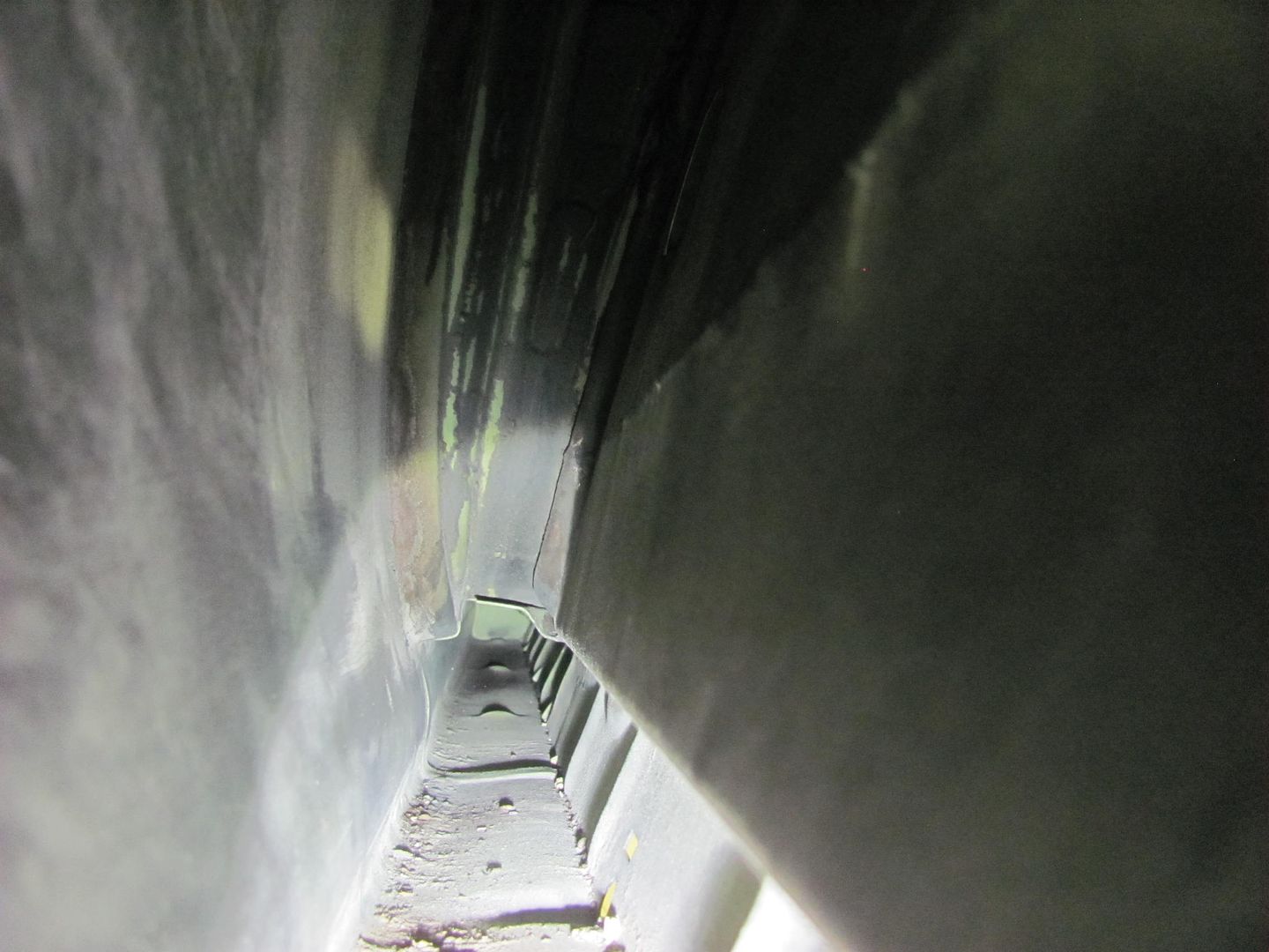
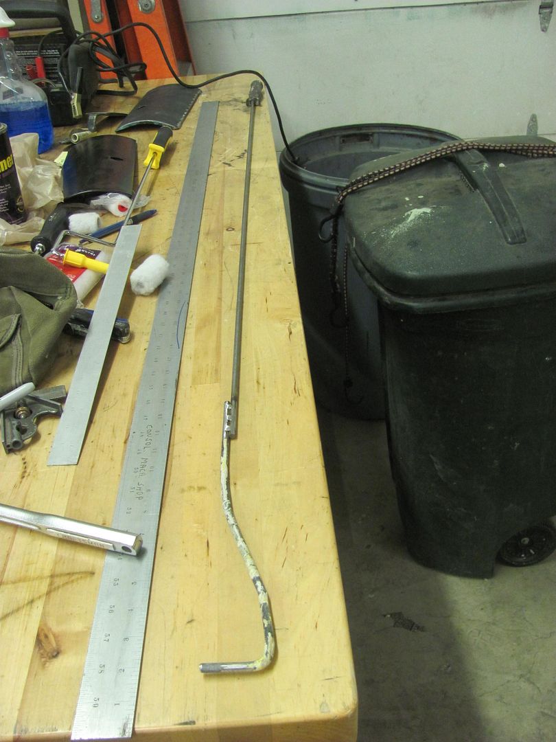
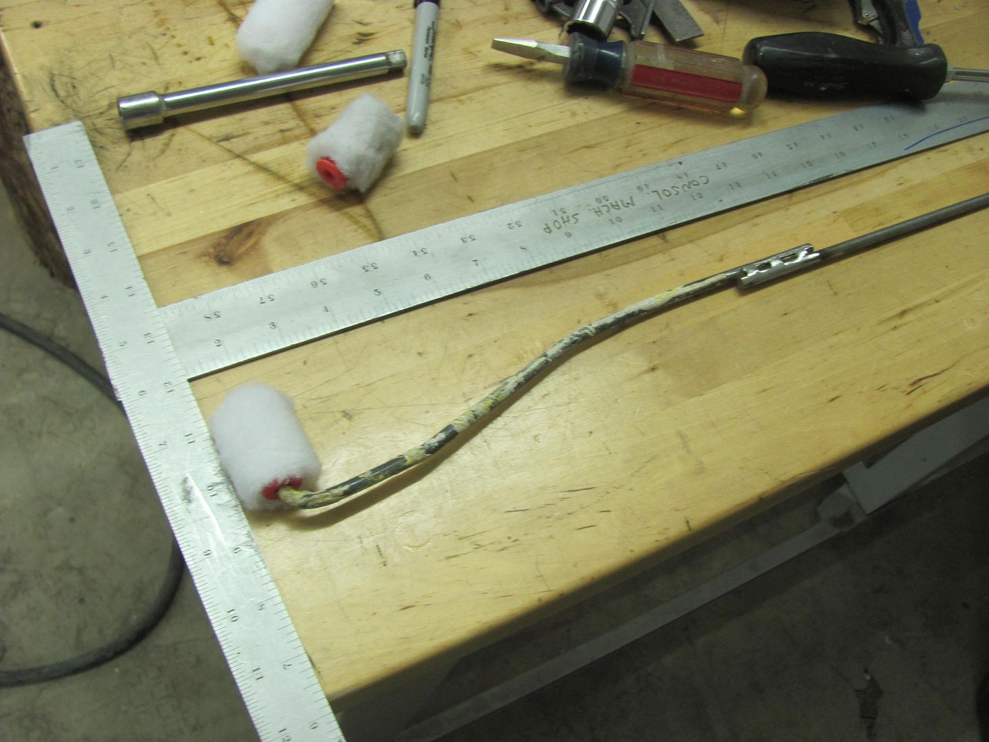
For the rocker, needed a bit more reach, both to scuff things up and roll on some paint. Here's the new multi-tool, with a 4' lift kit.
Scuffing attachment
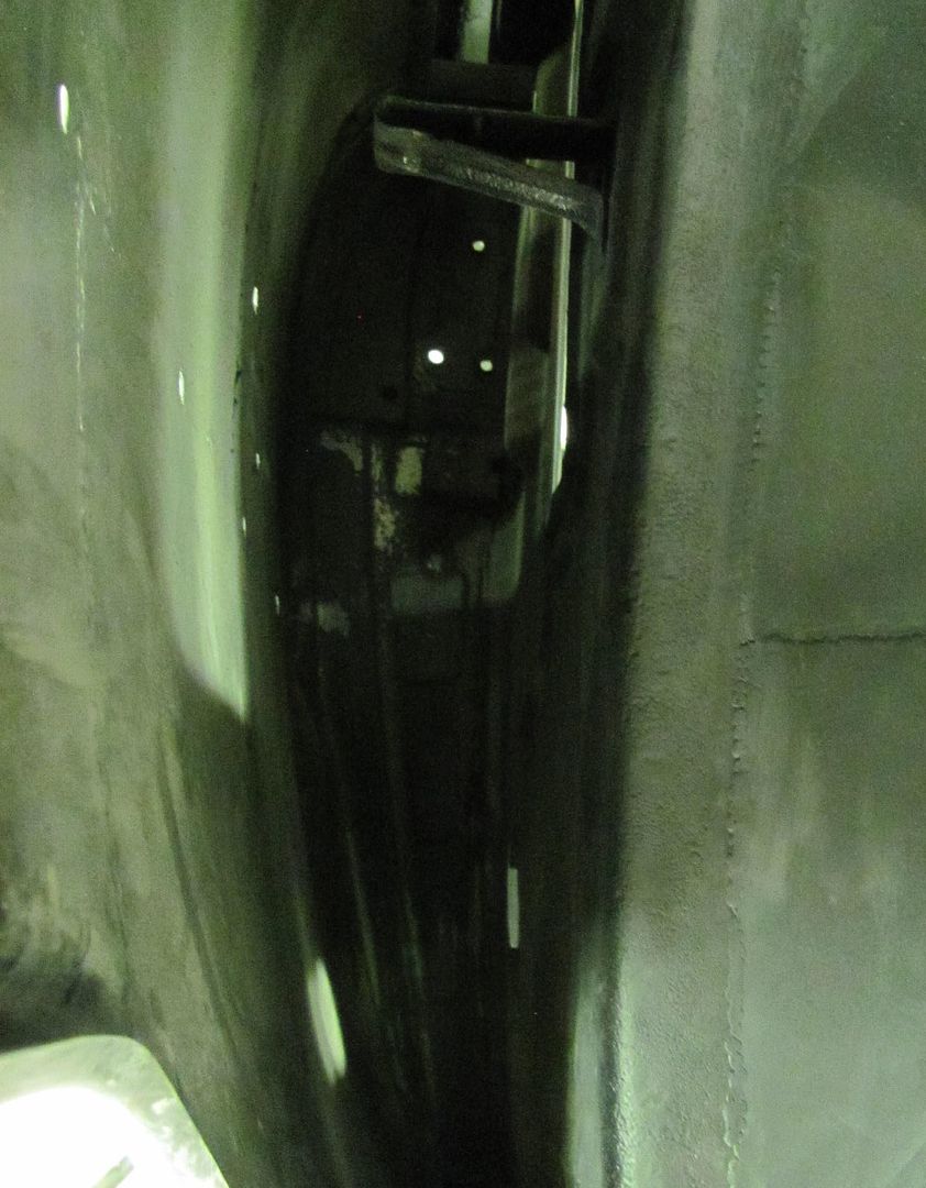
Target area..
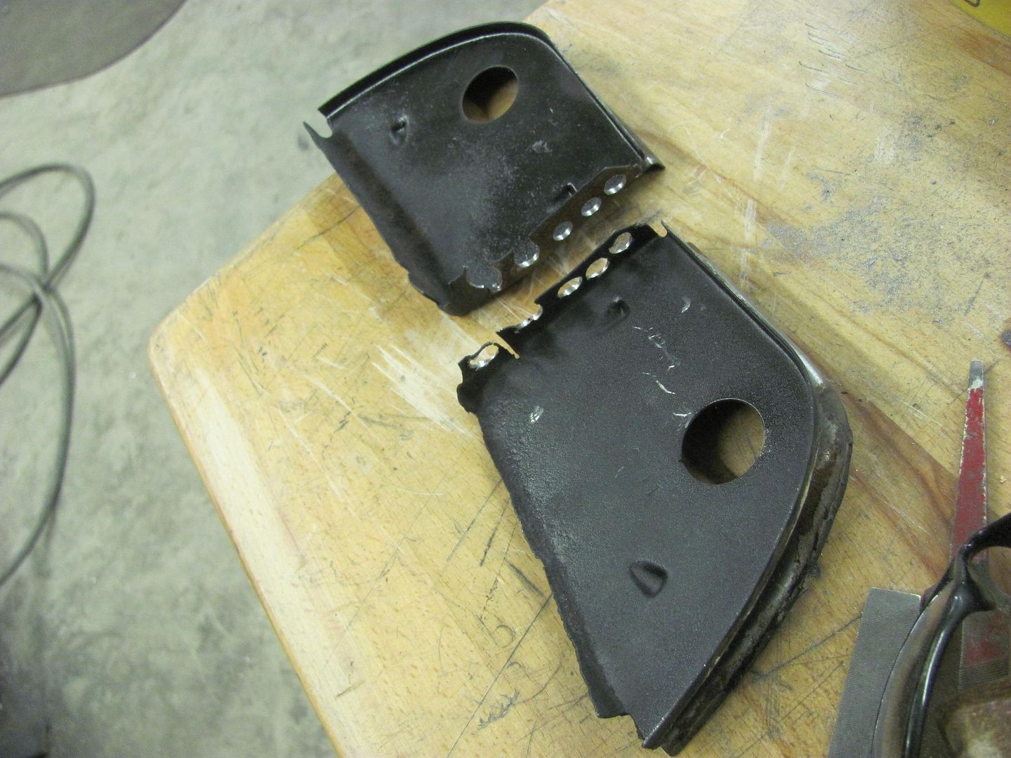
These dividers sit above the wheelwells inside the top of the quarter, and a bottom flange serves as a welding anchor for the top of the wheelwell. If they both had a bottom flange..
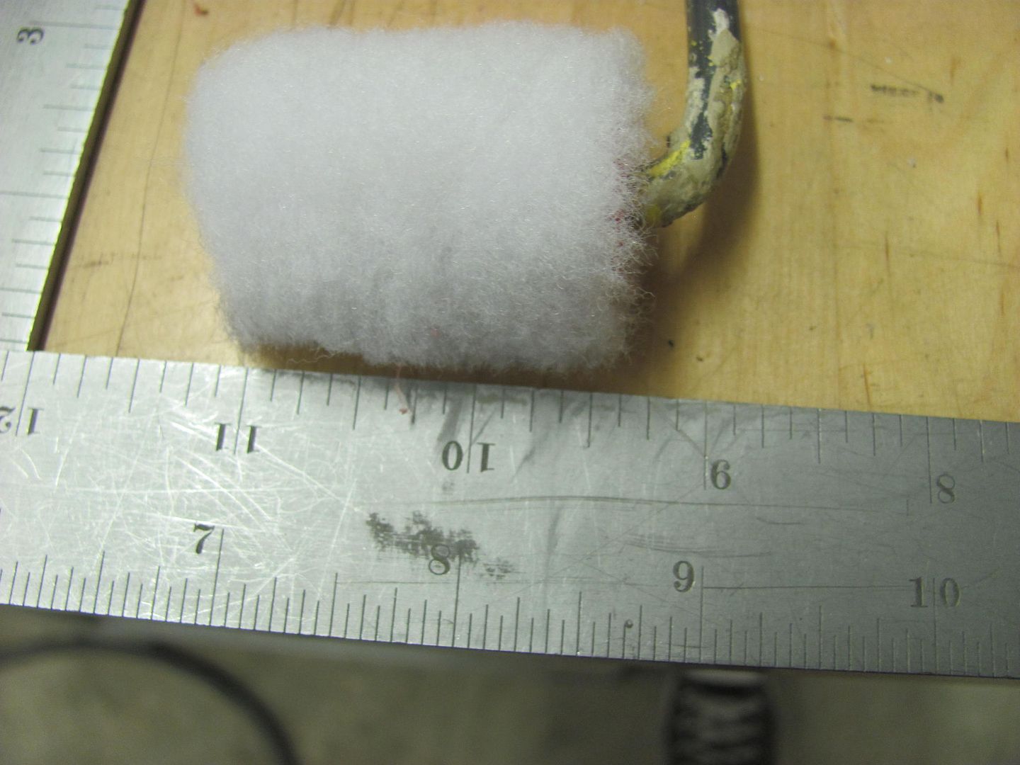
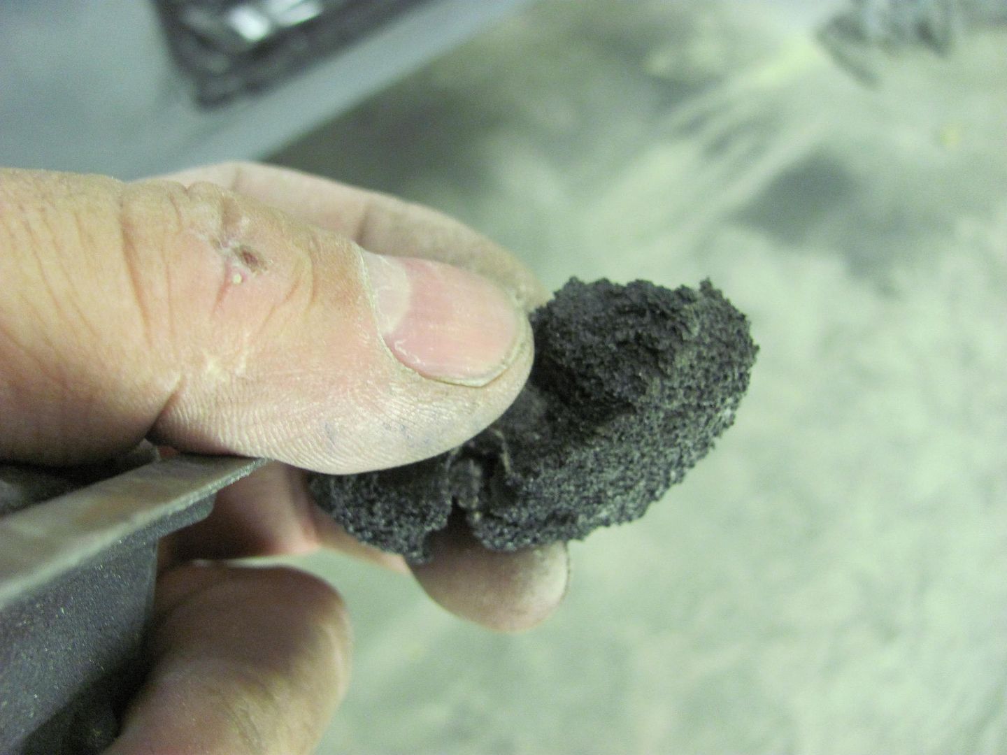
On top of those was a nice foam seal, which also served to trap water and cause one of our pits in the original quarter that we removed.
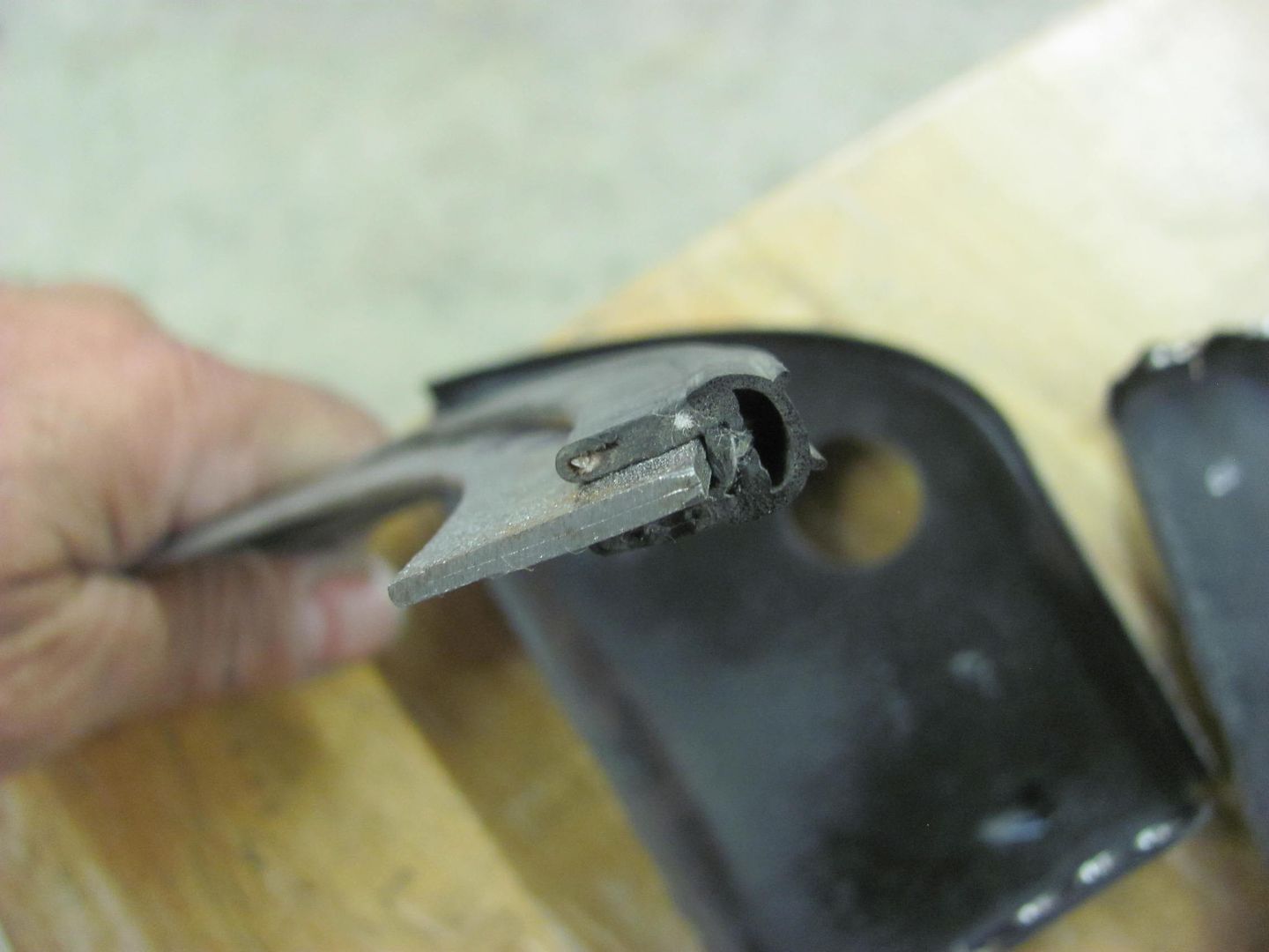
So the thought is to replace these with new ones made of 16 gauge, using a bulb seal at the top for less water absorption/retention...
With these now removed, you can see the still bare 1955 sheet metal that we'll also get covered with epoxy prior to installing the new brackets..
After all this fun, we loaded up one of the Biederman fenders and took it over to Saufley Sandblasting to get a quote on those. We'll get all the parts blasted individually, then sealed in epoxy primer, then assembled. After assembly, one more dose of Epoxy and they're off to the painter..
With the H/K Organic Green Kandy basecoat on the quarters down. To better get a feel for the test sprayout of the Kandy, a panel was made to simulate the top of the quarter, so we can better see the effects in the sunlight...
Next, epoxy in the cavities. I had looked at cavity spraying wands and the like, and did not care for what was available. So lets get basic, after all it is unseen when complete..
This area doesn't have to be pretty, so picked up this goodie at the local hardware store..
.....which should get enough on the inner quarter to seal things up..
For the rocker, needed a bit more reach, both to scuff things up and roll on some paint. Here's the new multi-tool, with a 4' lift kit.
Scuffing attachment
Target area..
These dividers sit above the wheelwells inside the top of the quarter, and a bottom flange serves as a welding anchor for the top of the wheelwell. If they both had a bottom flange..
On top of those was a nice foam seal, which also served to trap water and cause one of our pits in the original quarter that we removed.
So the thought is to replace these with new ones made of 16 gauge, using a bulb seal at the top for less water absorption/retention...
With these now removed, you can see the still bare 1955 sheet metal that we'll also get covered with epoxy prior to installing the new brackets..
After all this fun, we loaded up one of the Biederman fenders and took it over to Saufley Sandblasting to get a quote on those. We'll get all the parts blasted individually, then sealed in epoxy primer, then assembled. After assembly, one more dose of Epoxy and they're off to the painter..
Divcod
Well-known member
Robert,
I have an extra Divco man-door so if you have a need it let me know. Converted a NOS passenger door to a drivers door b flipping the hardware and then added SS hinges, so wont have a need for more doors. This is in pretty good shape so it might be better than the one you have.
I have an extra Divco man-door so if you have a need it let me know. Converted a NOS passenger door to a drivers door b flipping the hardware and then added SS hinges, so wont have a need for more doors. This is in pretty good shape so it might be better than the one you have.
Attachments


As I'm getting closer to transition to the next phase of my project car, I wonder if you would be willing to elaborate more on the 'block sanding' phase? For instance when sanding I assume you start with more course grit, but when you come across 'highs' or 'lows', do you 'bump' the metal to correct? Once done, there do you re-spray the epoxy and move on to a finer grit and repeat?
What are the instances where you use the Evercoat 416 and if so, why? Unable to access both sides to bump metal?
Sorry for perhaps trivial questions, but wanting to learn and do as much as possible to make this a true 'garage built' car.
--Gary B.
Current Project: 1971 Olds Cutlass Supreme
What are the instances where you use the Evercoat 416 and if so, why? Unable to access both sides to bump metal?
Sorry for perhaps trivial questions, but wanting to learn and do as much as possible to make this a true 'garage built' car.
--Gary B.
Current Project: 1971 Olds Cutlass Supreme
aggierailroad
Well-known member
I love your selfie-stick brush mod!
I love your selfie-stick brush mod!
That's a paint roller that's had a 4' piece of rod added.

As I'm getting closer to transition to the next phase of my project car, I wonder if you would be willing to elaborate more on the 'block sanding' phase? For instance when sanding I assume you start with more course grit, but when you come across 'highs' or 'lows', do you 'bump' the metal to correct? Once done, there do you re-spray the epoxy and move on to a finer grit and repeat?
What are the instances where you use the Evercoat 416 and if so, why? Unable to access both sides to bump metal?
Sorry for perhaps trivial questions, but wanting to learn and do as much as possible to make this a true 'garage built' car.
--Gary B.
Current Project: 1971 Olds Cutlass Supreme
With the entire car media blasted you get a clean but rough finish. You can then "block" the car to find any highs or lows that will show once scuffed with some 80 grit. So these can be bumped up or down as needed to save the need for quite so much filler. The epoxy sprayed cures into a semi-gloss finish that turns lighter once sanded, as you can see in the pictures above. So this serves as a guide coat in much the same way as the scuffing of the media blasted finish. Again, metal finish/bump as accessibility permits, use filler in the lows if it doesn't. block again, more primer, repeat....
Yarz
Well-known member
Is there a limit to the number of repetitions? In other words, at some point is the primer too thick (for example to handle stone chips, etc)?
Is there a limit to the number of repetitions? In other words, at some point is the primer too thick (for example to handle stone chips, etc)?
For the most part the blocking is removing much of the previous coats. Using the sandpaper on media blasted panels does a nice job of initially showing the highs and lows for some metal bumping, in addition to the same feature once blocking the primer. If access permits you can still bump the panels with the epoxy on it.
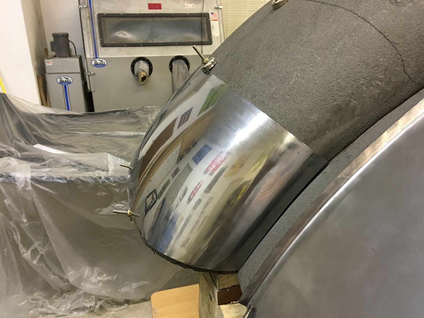
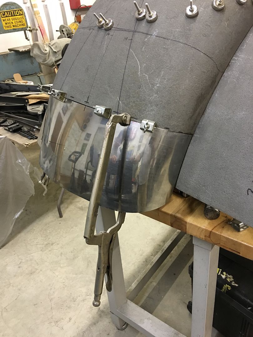
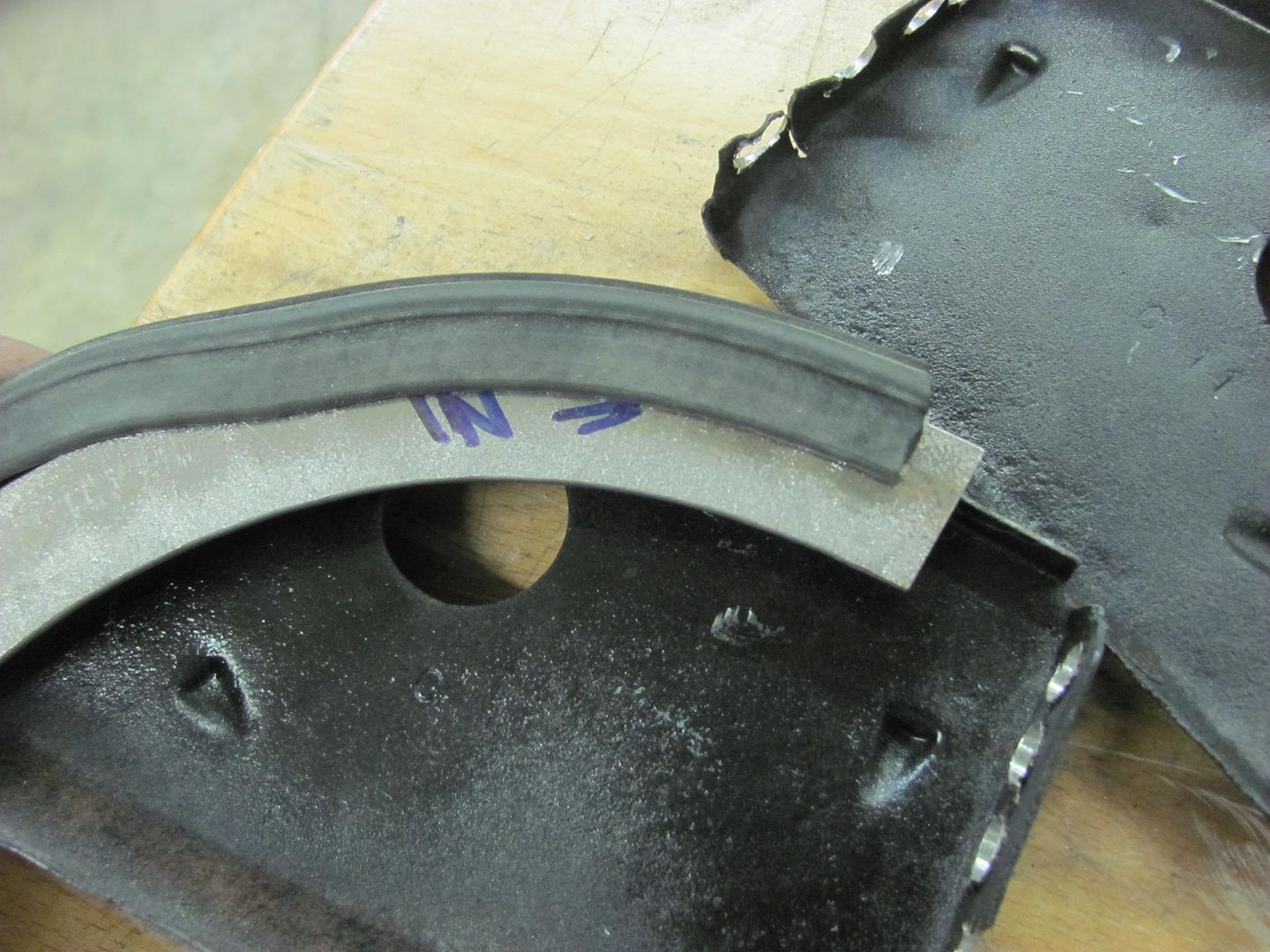
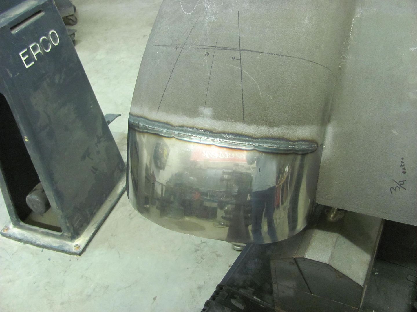
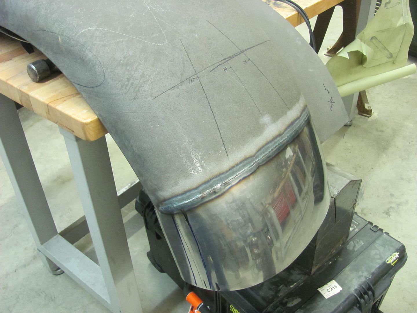
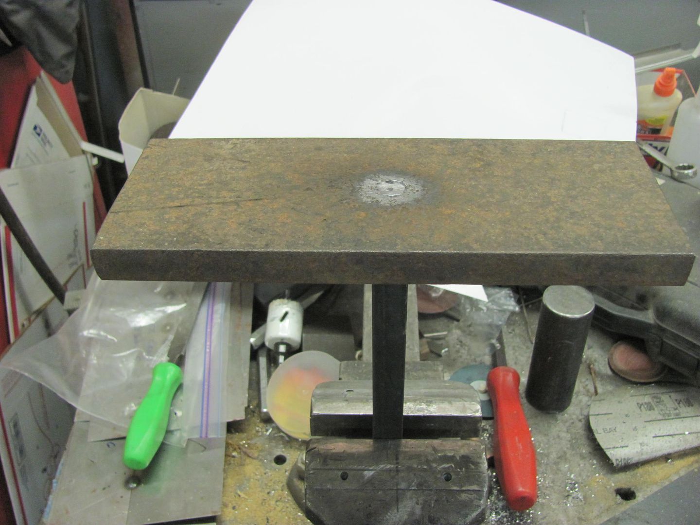
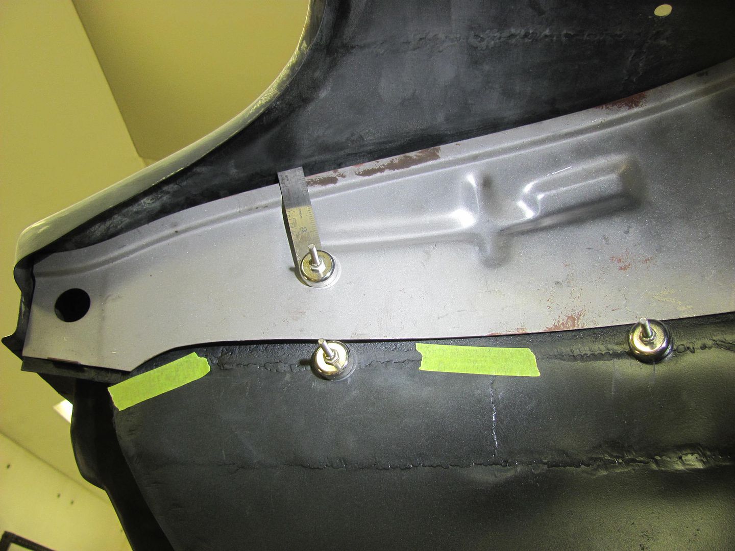
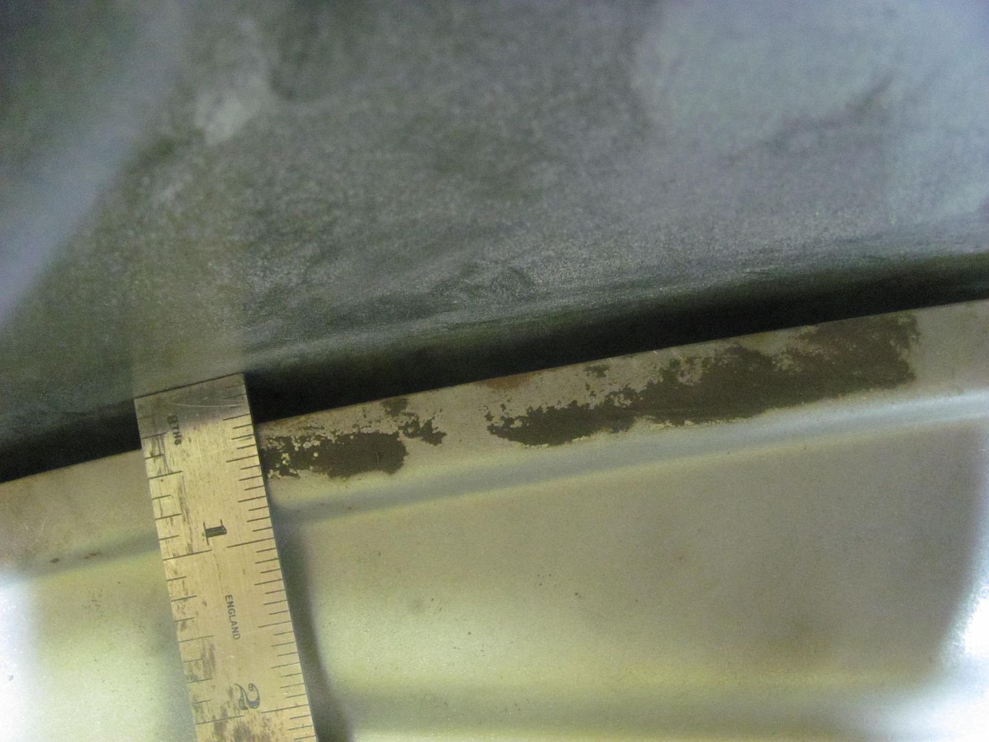
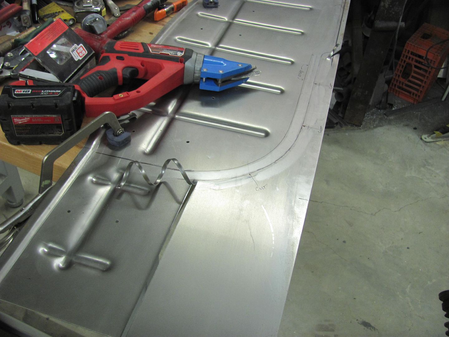
Time to break out the TIG welder. The new stumps for the upcoming metalshaping class work well as a welding table. The patch is securely clamped from inside to outside to get an accurate marking for tipping the fold around the wire.
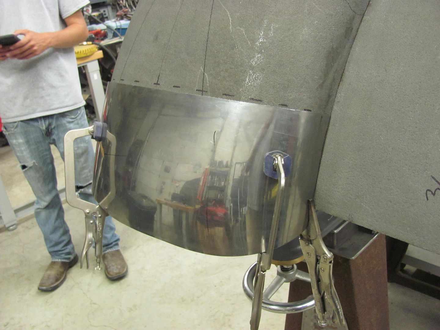
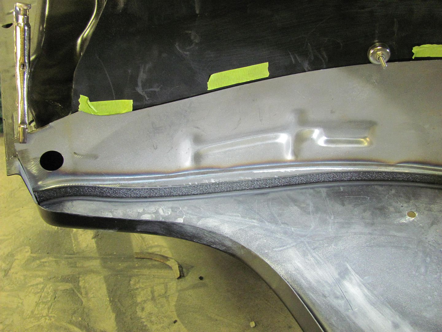
Flexible Spline is used to carry the opening mark down the patch...
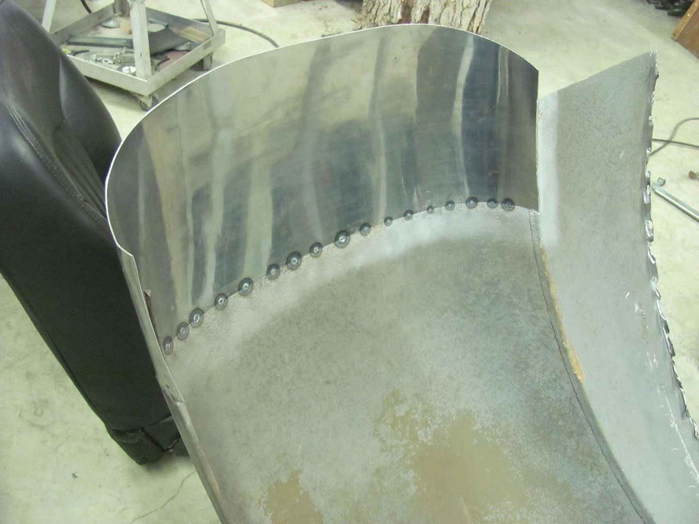
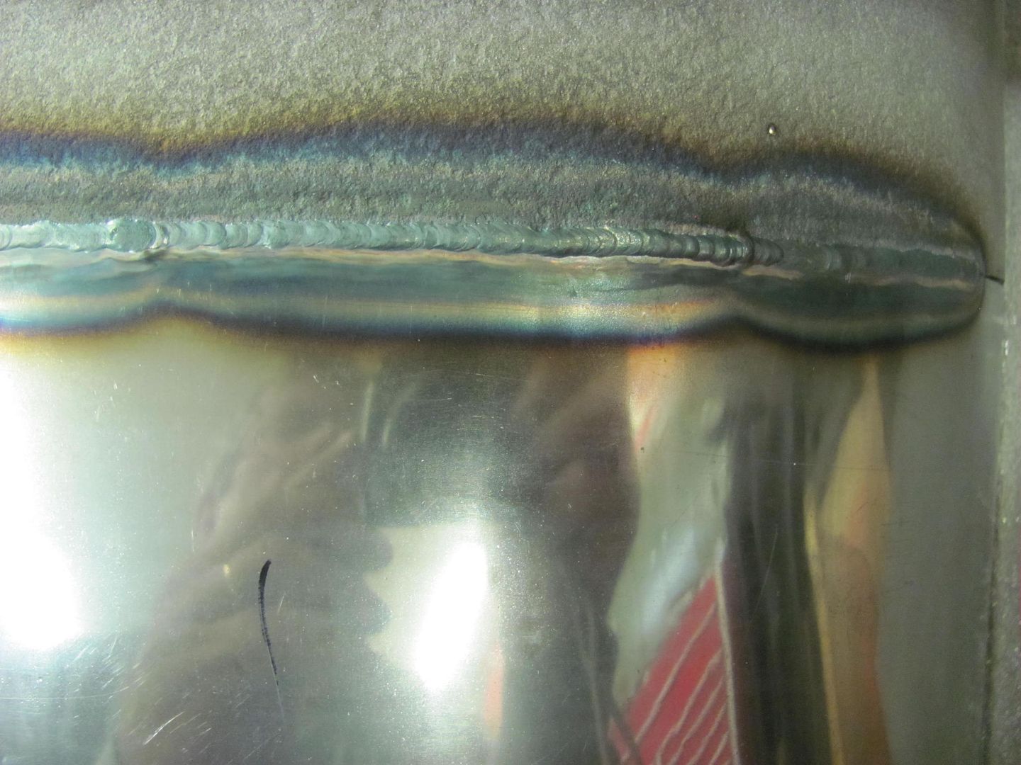
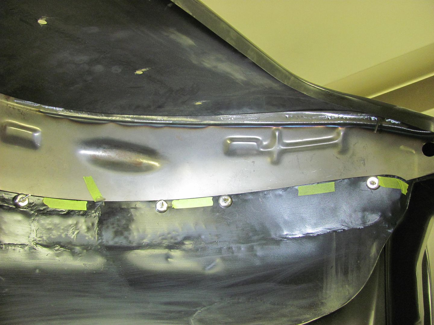
Tacked in with the TIG
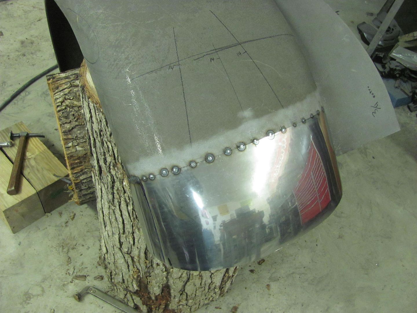
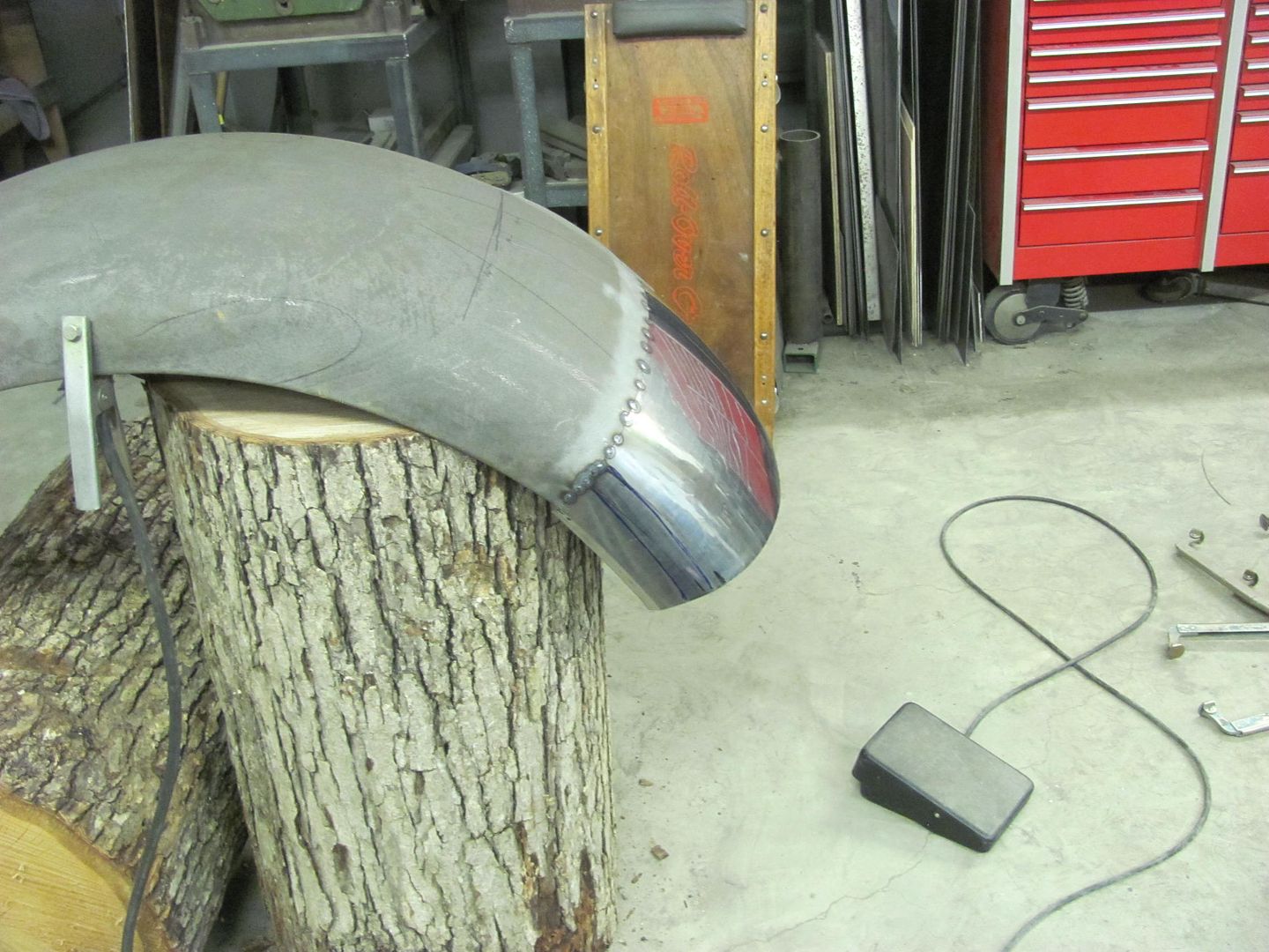
Next we'll wrap the wire and trim the front edge to size.
Flexible Spline is used to carry the opening mark down the patch...
Tacked in with the TIG
Next we'll wrap the wire and trim the front edge to size.
Thanks Royce!
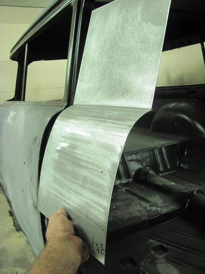
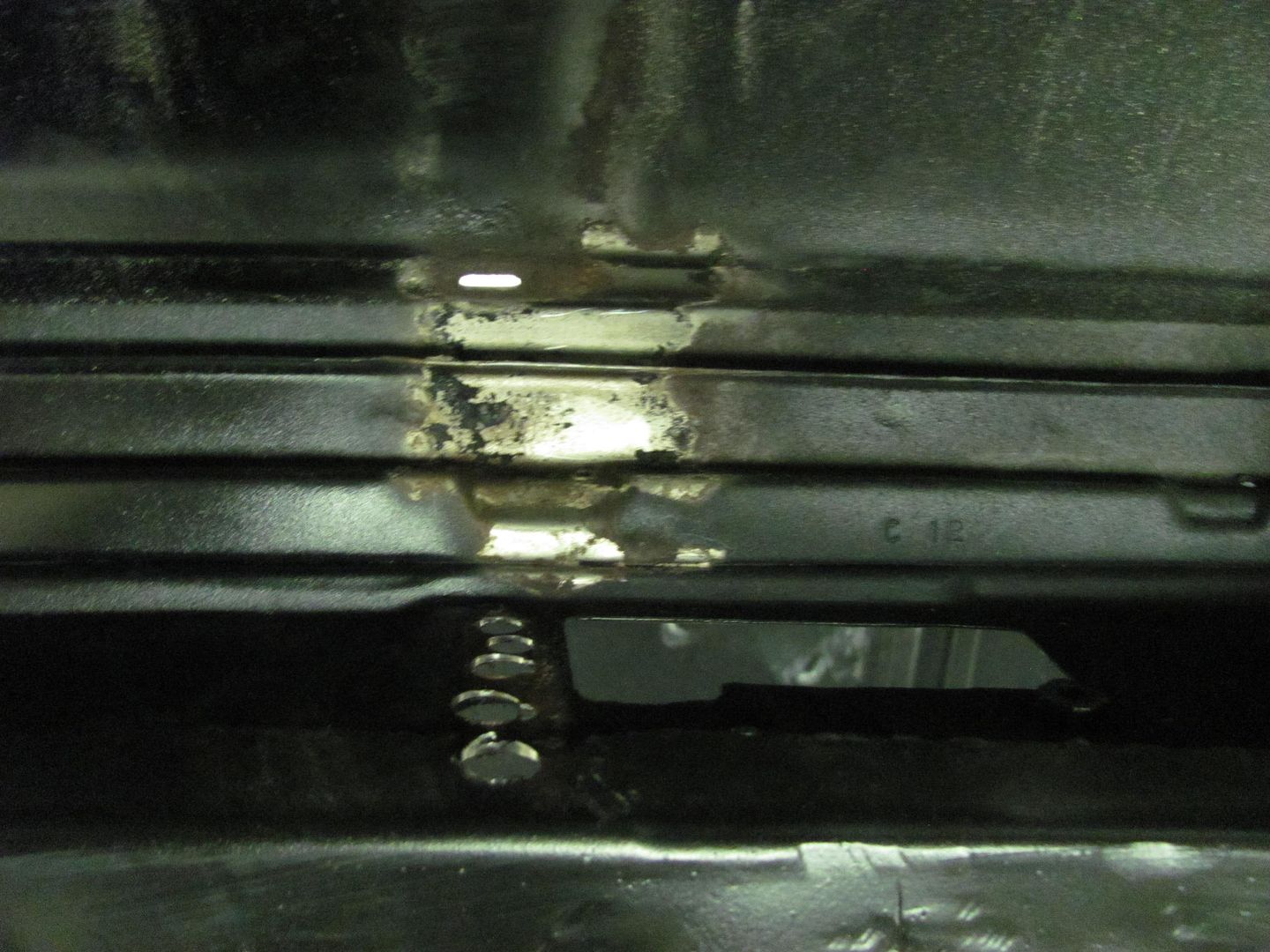
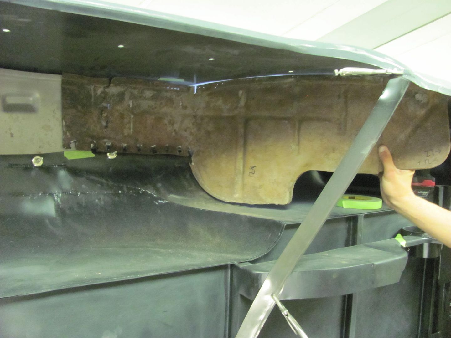
Working today on fitting up the wheel wells. The front half is re-popped and uses the same part as the sedans, the rear part is not available. Fitting the front, notice the right lower corner (as shown) tapers up with less overlap for plug/spot welding.
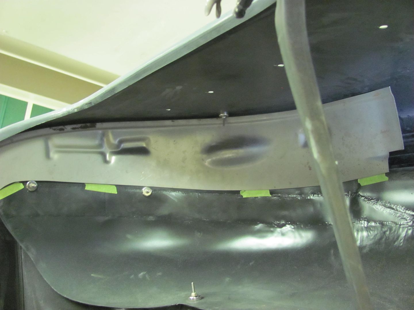
The rear section is NOT available in reproduction, and the notch you see there is for routing the fuel fill on a wagon tank. We've switched to a sedan tank to make room for dual exhaust, and given the widened wheel tubs and tires being used, no need in leaving such a gaping hole. So new parts it is.. The lower flap I'm holding is a separate piece that is spot welded on. In an effort to minimize moisture traps/rust generators in the future, we'll make this in one piece.
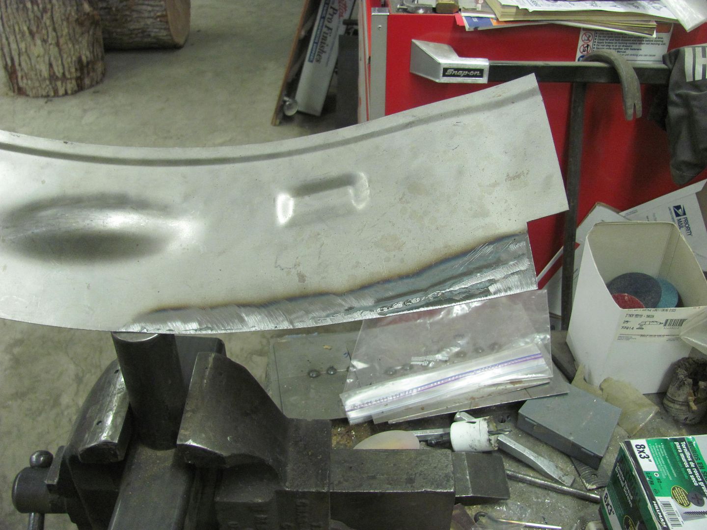
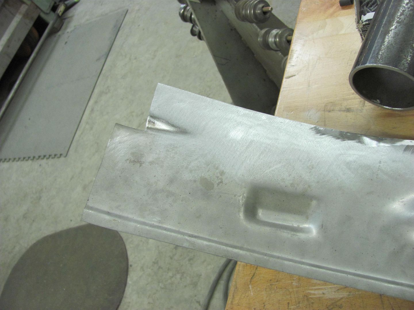
To fix our front repop, a piece of 18 gauge is TIG welded to give us a square corner...
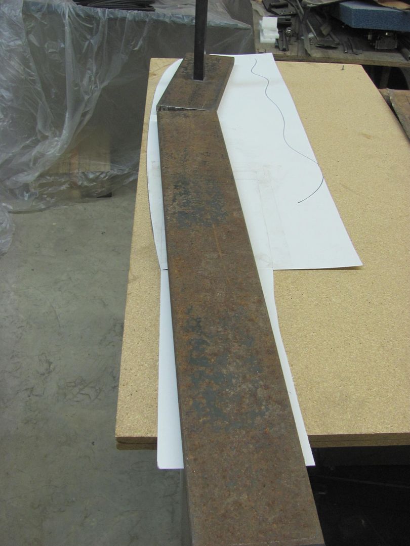
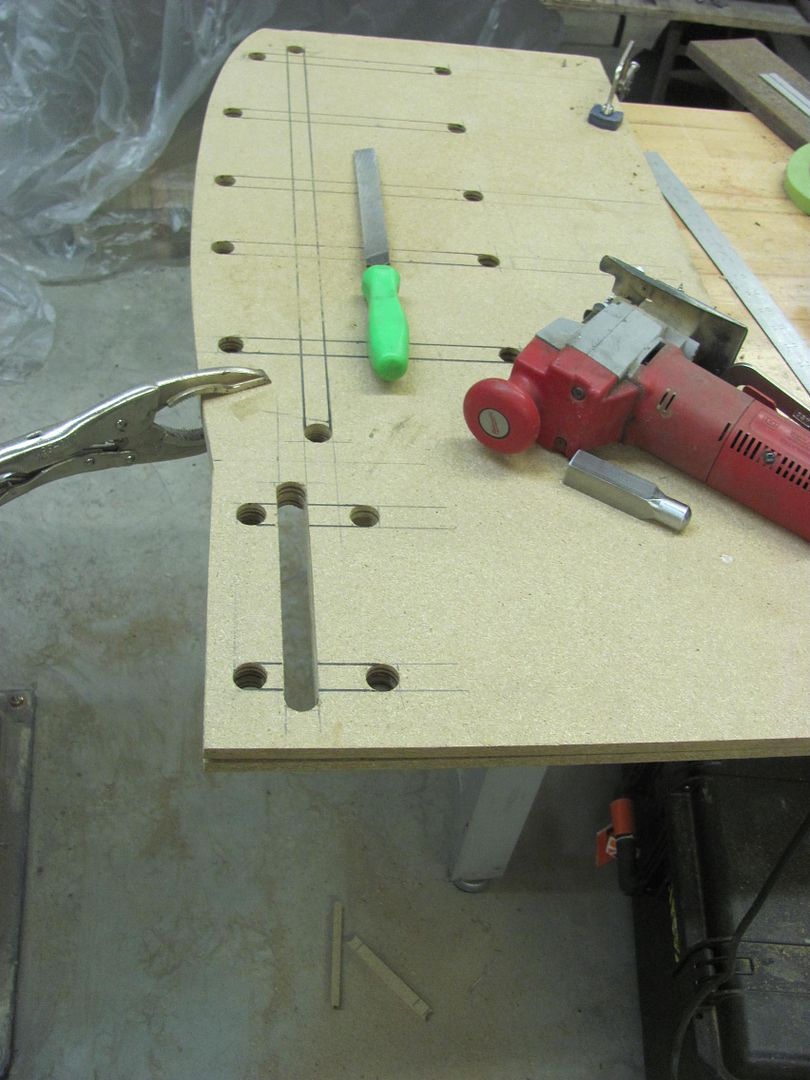
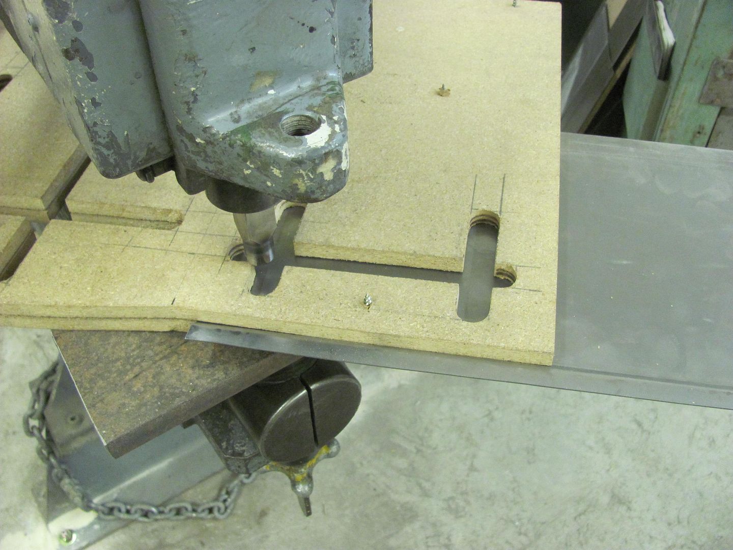
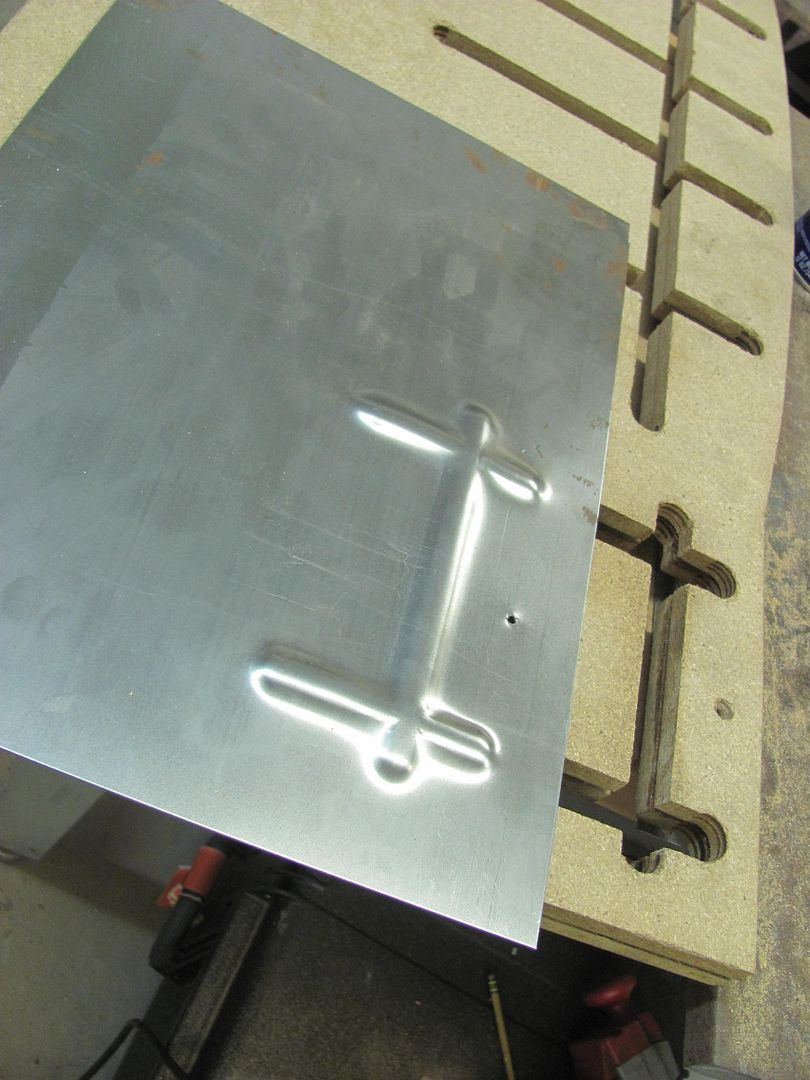
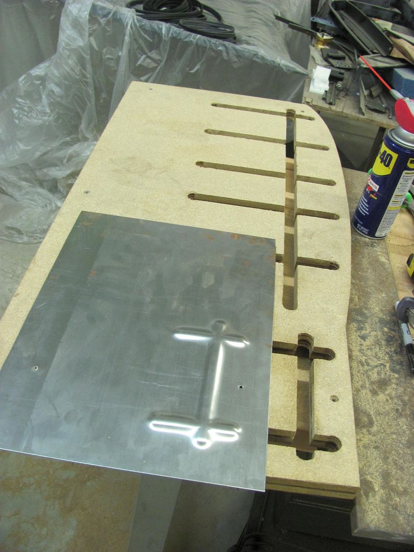
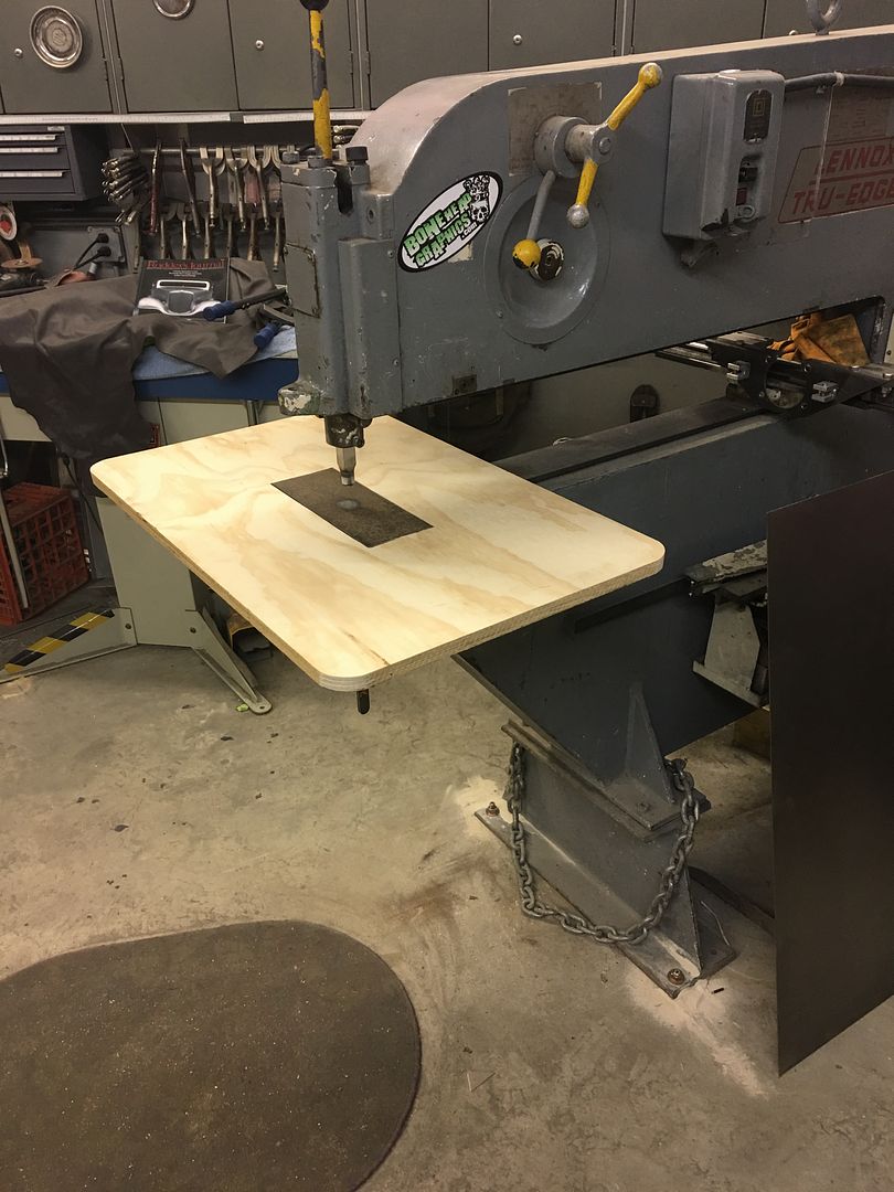
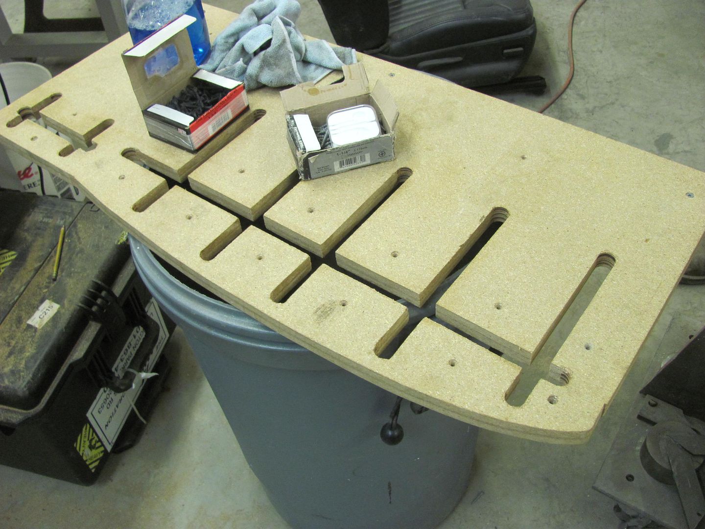
To make the new piece for the rear, we'll need a method to add beads that cross each other. This will entail a small table to use on the Lennox, an upper punch, and two pieces of matched MDF. Slots will be cut into the MDF, the top used as a guide for the punch, the bottom acts as our bottom die as it "rests" on the table..
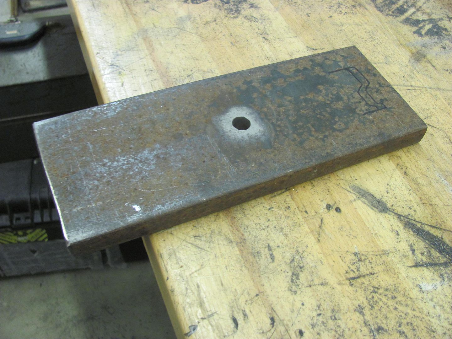
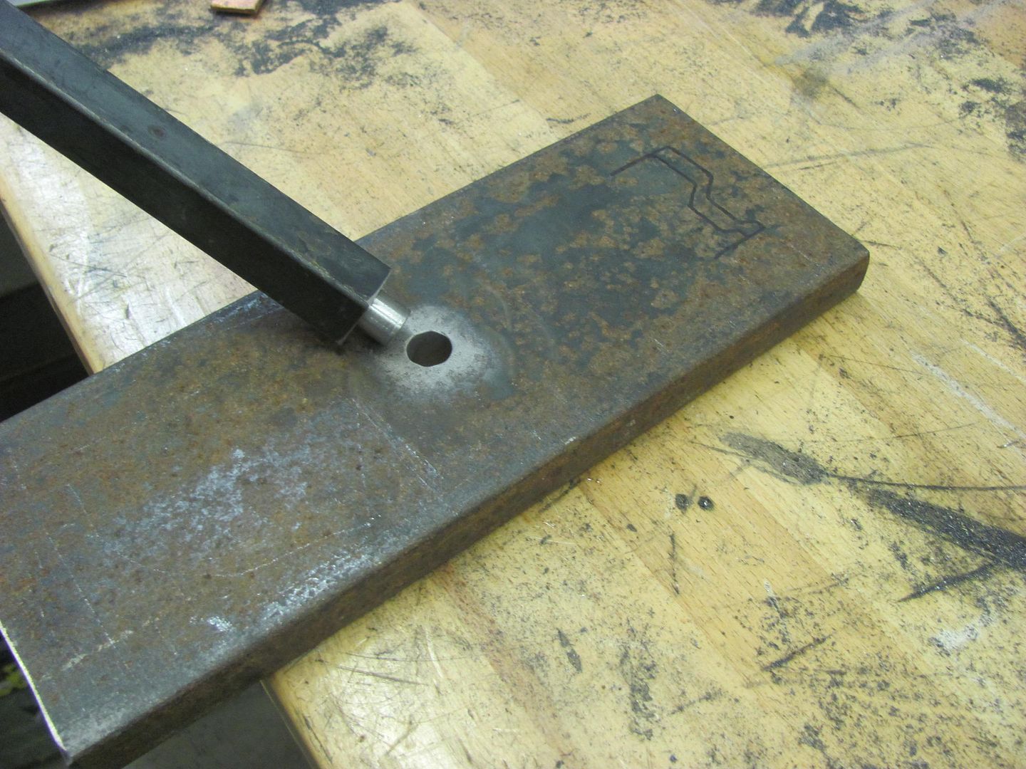
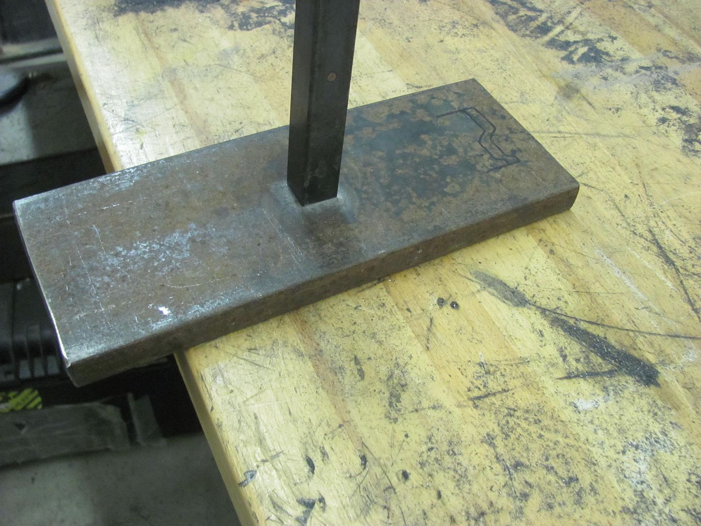
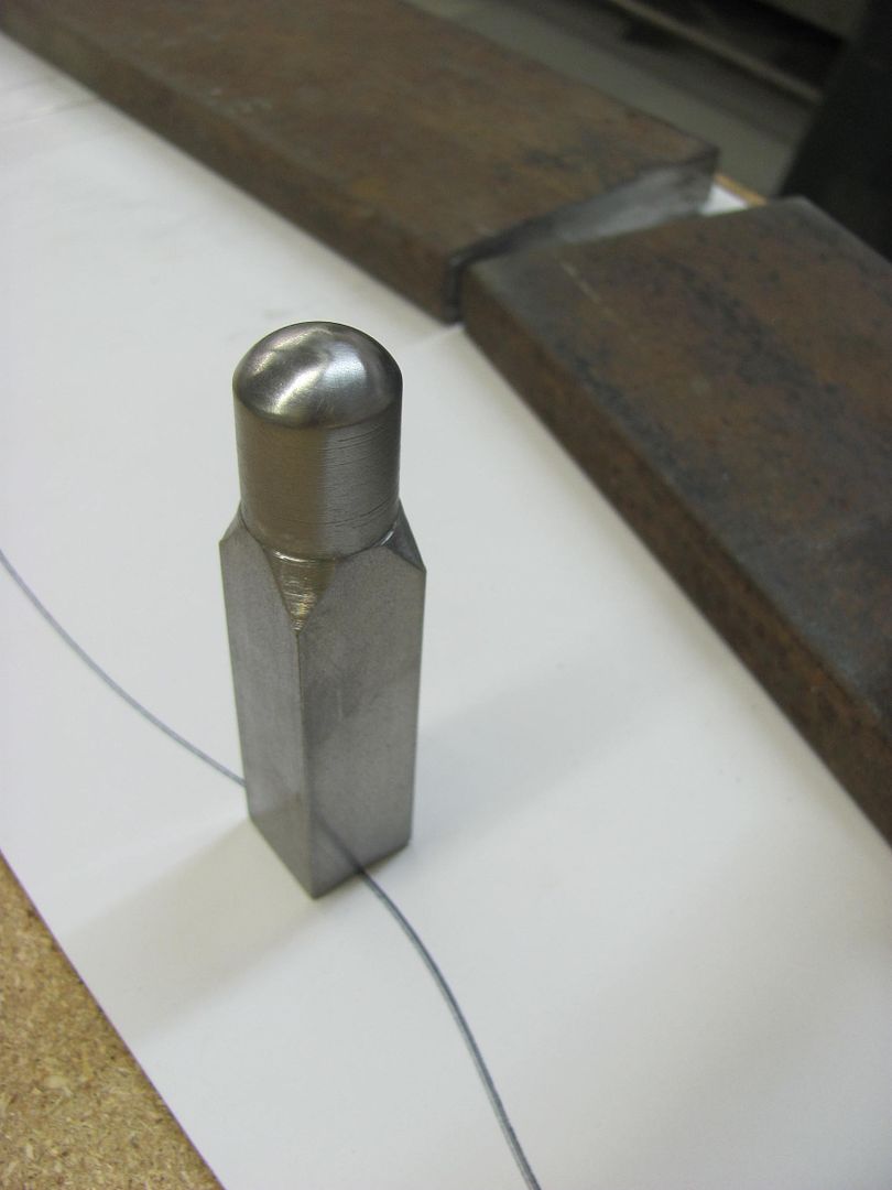
The table will be supported in the lower tool holder using a 3/4 shank. The end is turned down to 1/2" to mate into a 1/2" hole in the 4 x 12 table, which is then plug welded.
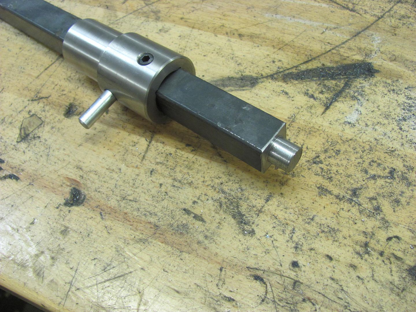
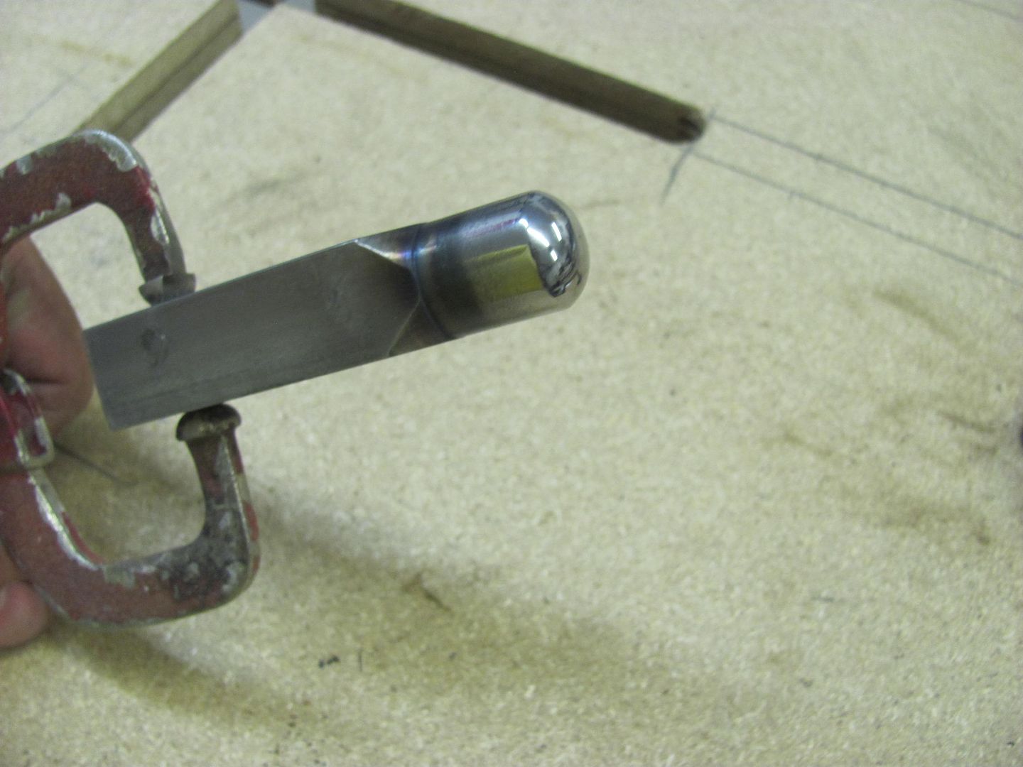
For an upper punch, we'll use some 3/4 oil hardening 4140, making it less pointed than the original just in case we want to use it for something besides the 55.
For a bead guide we first need to get a good template of the inside of the quarter. The adjustable spline comes in handy...
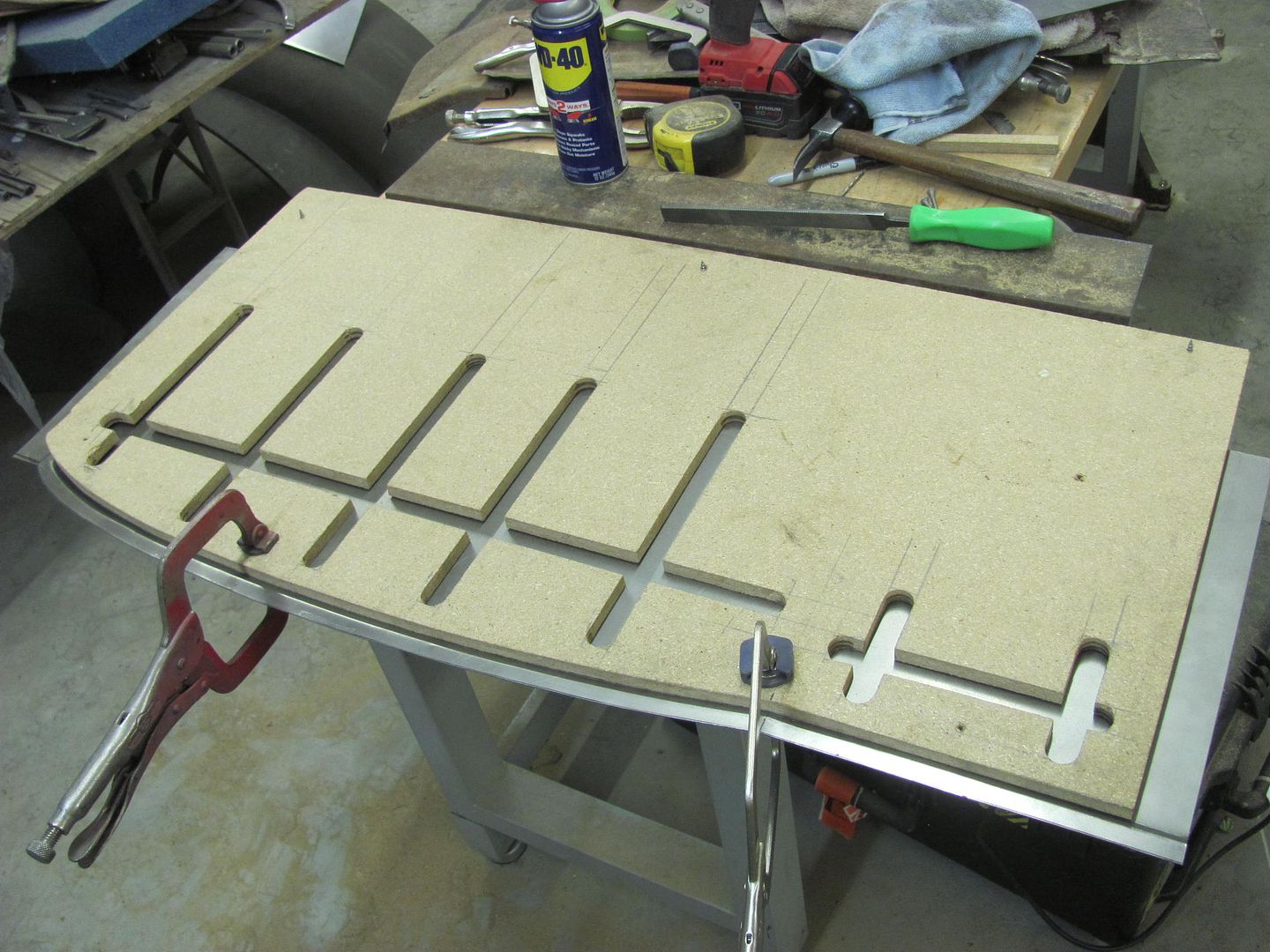
MDF is screwed together and then the edge profile cut..
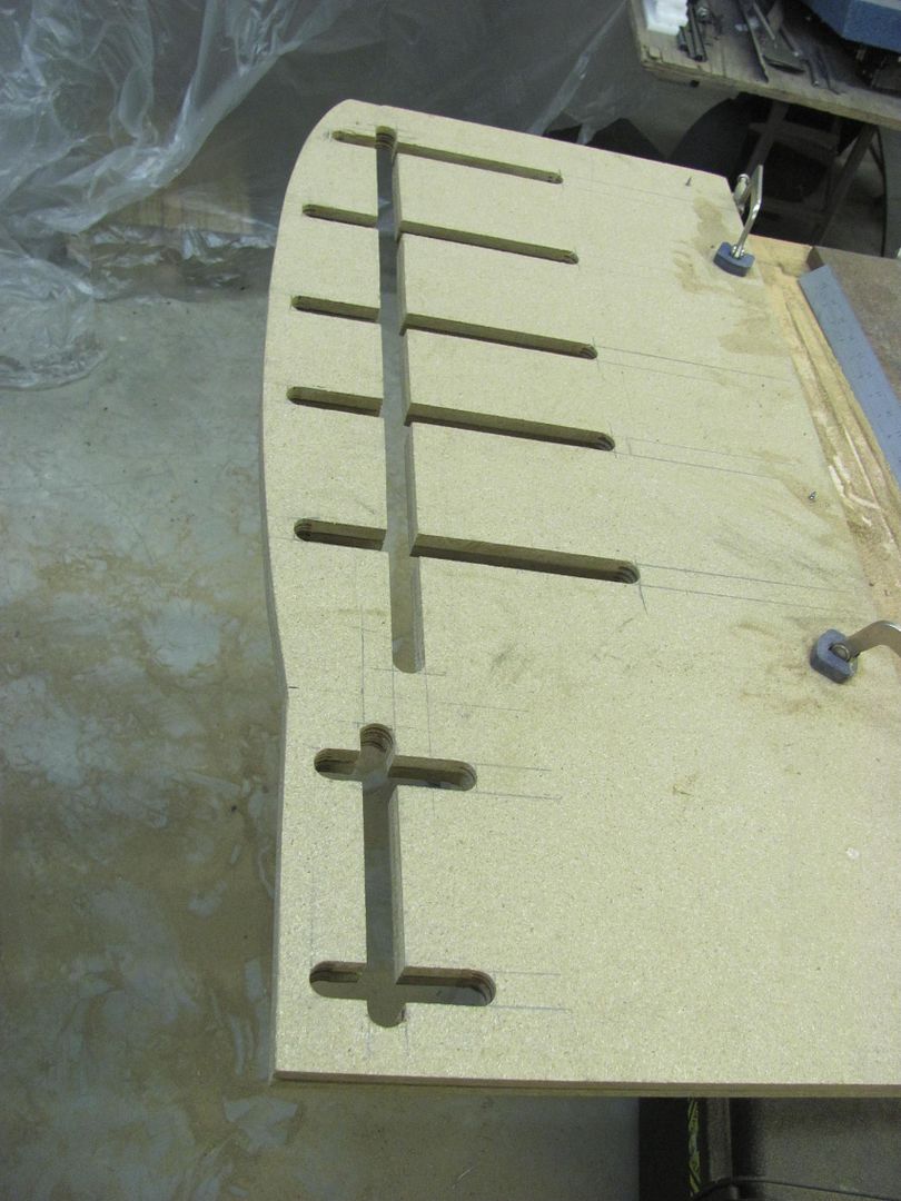
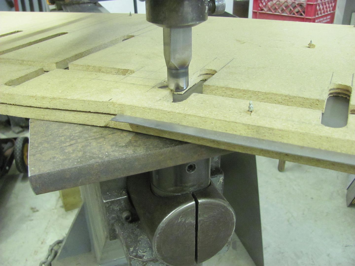
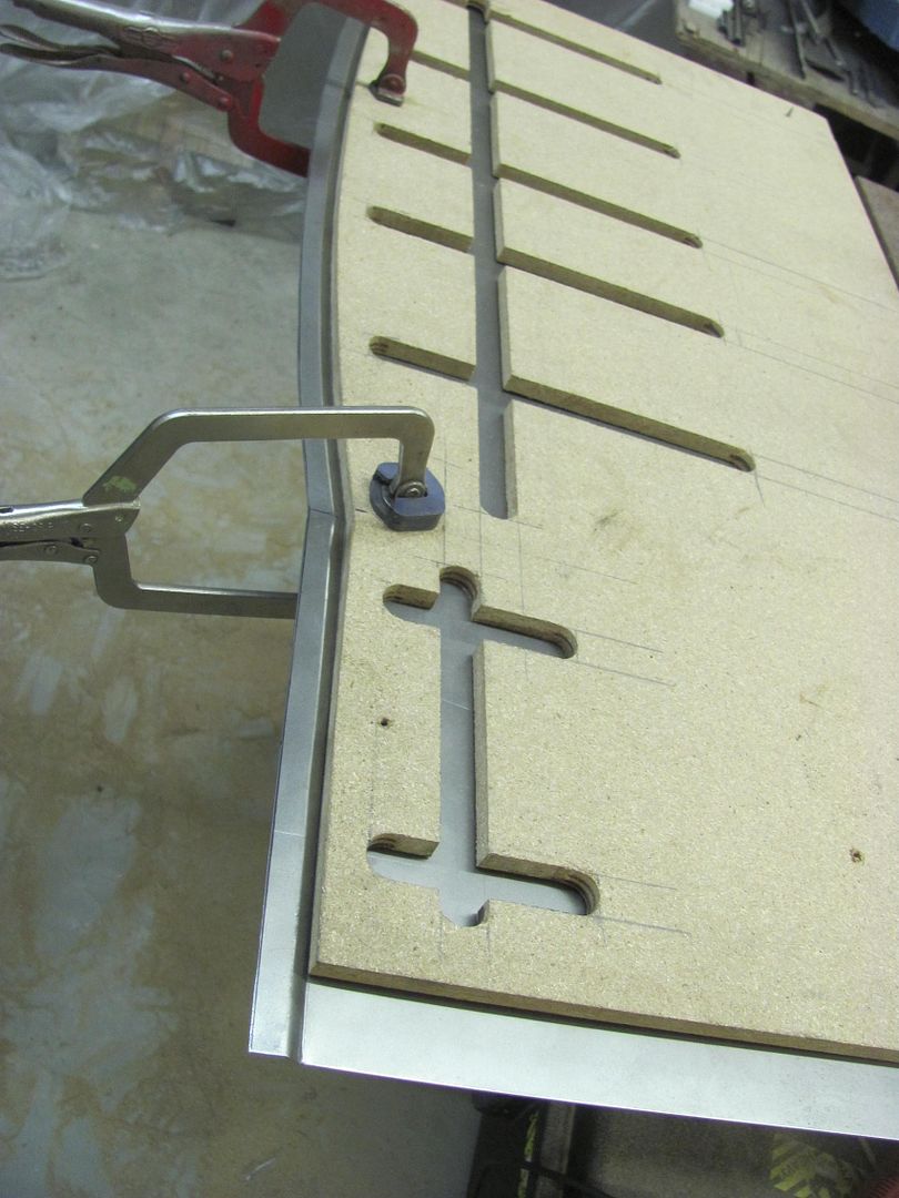
Cutting our bead pattern..
The offset of the original for the quarter seal is added using a tipping die in the Lennox, slight modification on the backstop for the correct width..
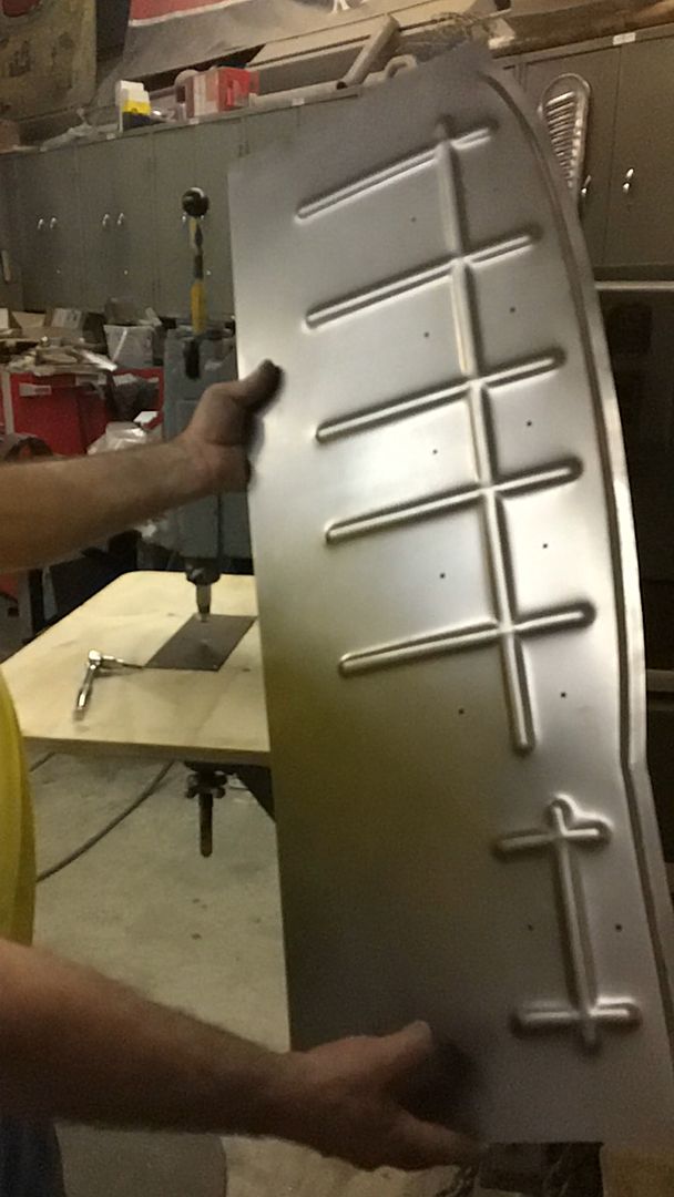
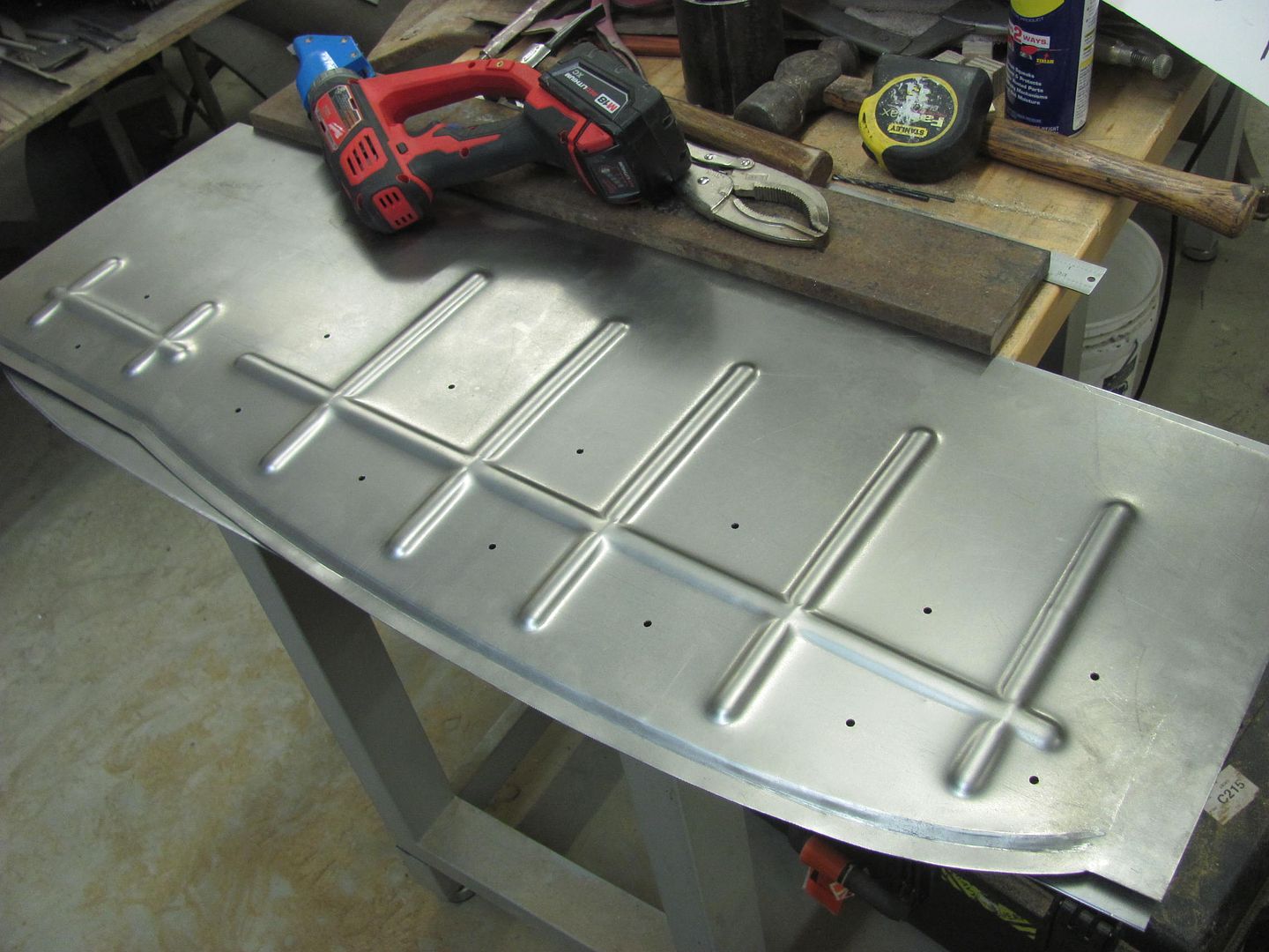
New matches the repop....
This seal will be used against the inside of the quarter..
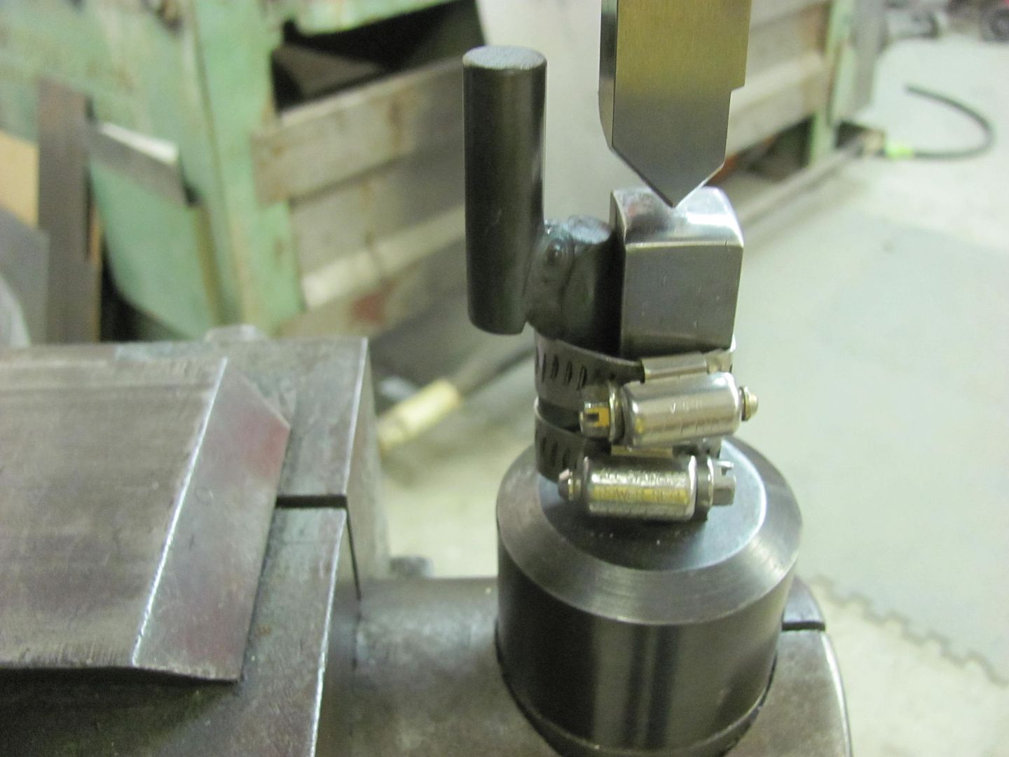
Running a test pattern... The table height is adjusted to set the punch depth...
All clamped up, ready to go. Kyle has already left for the day so we'll finish up next time..
Working today on fitting up the wheel wells. The front half is re-popped and uses the same part as the sedans, the rear part is not available. Fitting the front, notice the right lower corner (as shown) tapers up with less overlap for plug/spot welding.
The rear section is NOT available in reproduction, and the notch you see there is for routing the fuel fill on a wagon tank. We've switched to a sedan tank to make room for dual exhaust, and given the widened wheel tubs and tires being used, no need in leaving such a gaping hole. So new parts it is.. The lower flap I'm holding is a separate piece that is spot welded on. In an effort to minimize moisture traps/rust generators in the future, we'll make this in one piece.
To fix our front repop, a piece of 18 gauge is TIG welded to give us a square corner...
To make the new piece for the rear, we'll need a method to add beads that cross each other. This will entail a small table to use on the Lennox, an upper punch, and two pieces of matched MDF. Slots will be cut into the MDF, the top used as a guide for the punch, the bottom acts as our bottom die as it "rests" on the table..
The table will be supported in the lower tool holder using a 3/4 shank. The end is turned down to 1/2" to mate into a 1/2" hole in the 4 x 12 table, which is then plug welded.
For an upper punch, we'll use some 3/4 oil hardening 4140, making it less pointed than the original just in case we want to use it for something besides the 55.
For a bead guide we first need to get a good template of the inside of the quarter. The adjustable spline comes in handy...
MDF is screwed together and then the edge profile cut..
Cutting our bead pattern..
The offset of the original for the quarter seal is added using a tipping die in the Lennox, slight modification on the backstop for the correct width..
New matches the repop....
This seal will be used against the inside of the quarter..
Running a test pattern... The table height is adjusted to set the punch depth...
All clamped up, ready to go. Kyle has already left for the day so we'll finish up next time..
Last edited:
EdT
Well-known member
So, the bottoms of the beads are in "free air" with the depth set on the power hammer and the shape defined by the punch. Apparently, the indexing speed prevents ripples in the bead and the MDF provides enough clamping that you don't get panel distortion and the beads are pure stretch. As a bonus, your tooling is good for left and right parts. I really love your posts. Thanks for taking the time to show how you do stuff.
Kevin54
MEMBER EMERITUS
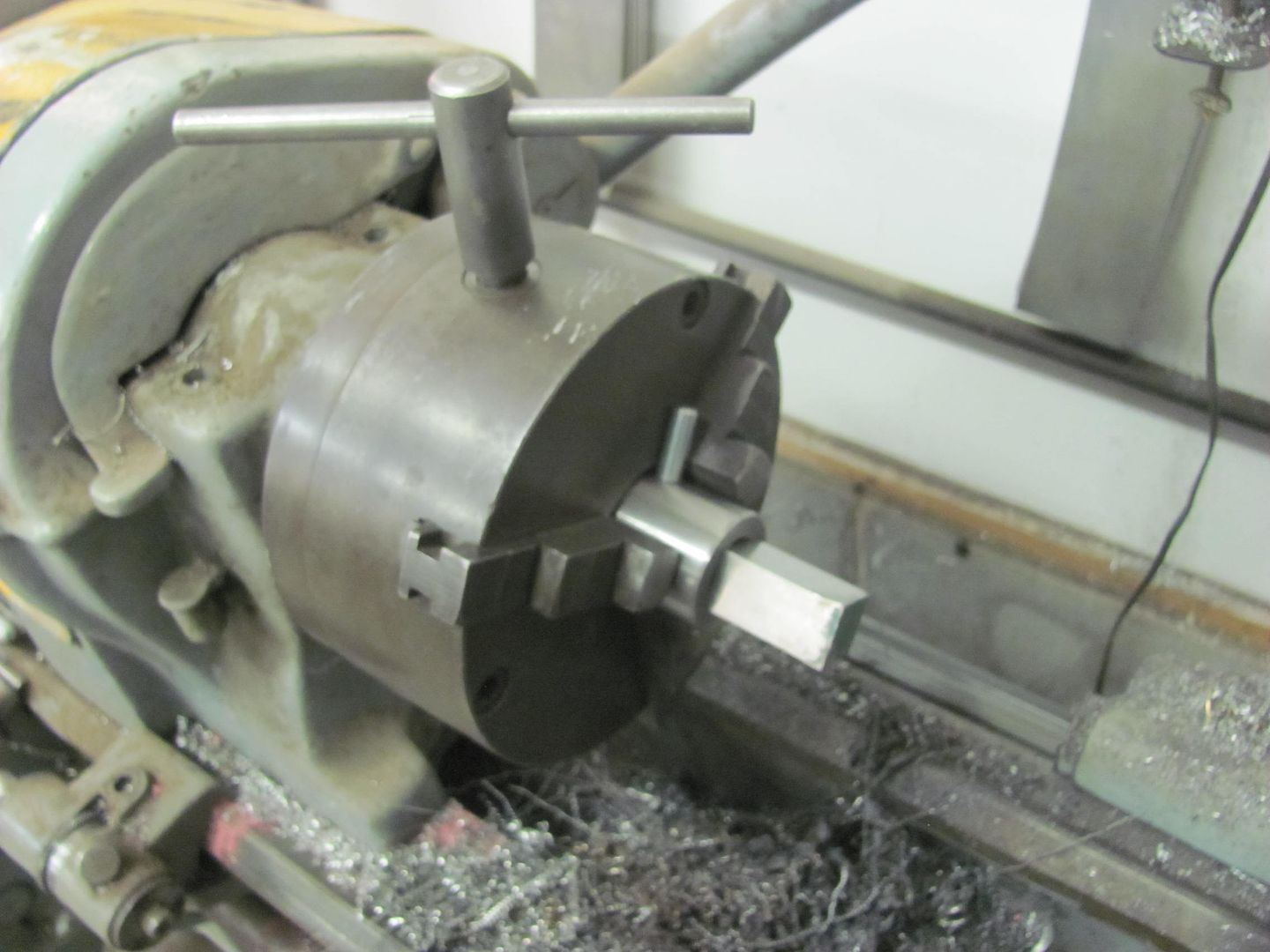
Robert....I just popped in to get caught up. And as usual, FANTASTIC work. I saw this picture and just wanted to comment. And I know that you know better and just did this for picture purposes, but for others that are new to lathe work, and have their own lathes at home.....NEVER EVER leave a chuck key in the chuck of a lathe. It is so easy to forget about it and turn the lathe on. In doing so, you can damage the lathe, and most importantly, you can damage yourself. I have seen old time toolmakers make the same mistake, damaging the bed way, and one managed to fracture his wrist when the chuck key hit him.
I just wanted to mention it, and in no way am I busting your chops. I just want to make others aware. I cringe whenever I see a chuck key in a lathe.
Jim Johnstone
Well-known member
I'll second this, my trade school teacher was a hard ***, if he caught us with a key in the chuck and our hands weren't still touching it, we were off the lathes for the rest of the day.
Robert....I just popped in to get caught up. And as usual, FANTASTIC work. I saw this picture and just wanted to comment. And I know that you know better and just did this for picture purposes, but for others that are new to lathe work, and have their own lathes at home.....NEVER EVER leave a chuck key in the chuck of a lathe. It is so easy to forget about it and turn the lathe on. In doing so, you can damage the lathe, and most importantly, you can damage yourself. I have seen old time toolmakers make the same mistake, damaging the bed way, and one managed to fracture his wrist when the chuck key hit him.
I just wanted to mention it, and in no way am I busting your chops. I just want to make others aware. I cringe whenever I see a chuck key in a lathe.
So, the bottoms of the beads are in "free air" with the depth set on the power hammer and the shape defined by the punch. Apparently, the indexing speed prevents ripples in the bead and the MDF provides enough clamping that you don't get panel distortion and the beads are pure stretch. As a bonus, your tooling is good for left and right parts. I really love your posts. Thanks for taking the time to show how you do stuff.
Exactly!
Robert....I just popped in to get caught up. And as usual, FANTASTIC work. I saw this picture and just wanted to comment. And I know that you know better and just did this for picture purposes, but for others that are new to lathe work, and have their own lathes at home.....NEVER EVER leave a chuck key in the chuck of a lathe. It is so easy to forget about it and turn the lathe on. In doing so, you can damage the lathe, and most importantly, you can damage yourself. I have seen old time toolmakers make the same mistake, damaging the bed way, and one managed to fracture his wrist when the chuck key hit him.
I just wanted to mention it, and in no way am I busting your chops. I just want to make others aware. I cringe whenever I see a chuck key in a lathe.
I'll second this, my trade school teacher was a hard ***, if he caught us with a key in the chuck and our hands weren't still touching it, we were off the lathes for the rest of the day.
Kevin, bust away! The chuck key always sits in the tray, and I'm going to attribute this to squirrel syndrome, I was tightening the fixture in the chuck, wait, I need to get a picture, then went on to tighten the other two screws. Doesn't justify it, just the way it happened. Glad to see you guys are on top of things!

Last edited:
ODIS
Well-known member
Have thoroughly enjoyed reading this thread not only for the technical value and process; it is because there is real passion for welding and metal shaping that is seen as pure art form.
On the second go round of reading, more details emerge for me and the process becomes clearer and it makes me want to try my hand making some bends and welding up some panels..... Only if it were to be a reality for me since you make it looks so easy, there is very clear knowledge now, would have my hands full of very large holes blown through the metal.... Time, practice, patience, repeat might get me to the level of talent you have in your little finger.
Further, this thread brings back some very cherished memories of the first car in my life (actually a lot of "firsts" in this car), a '55 Chevy 2 door station wagon given to me from my Dad in 1967. Lots of rust, a nasty old 235Ci 6 cylinder engine with 3-speed on the tree. Did my best to patch up the rusted headlight eyebrows and quarter panels, patch up the dents (of course with bondo) and have the car painted for the $ 39.95 special. Needed to get rid of the 6 in favor of a 283 V-8 punched out .040 over to 292 and a big 4 barrel carb. Know too, replacing spider gears in the rear end became very easy for me....

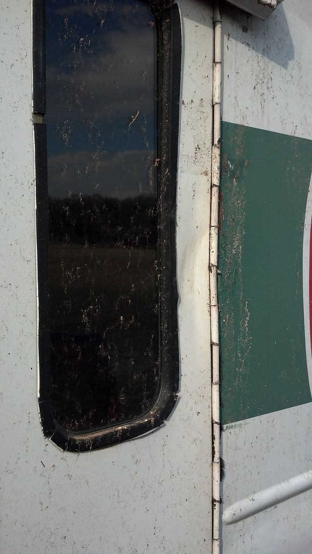
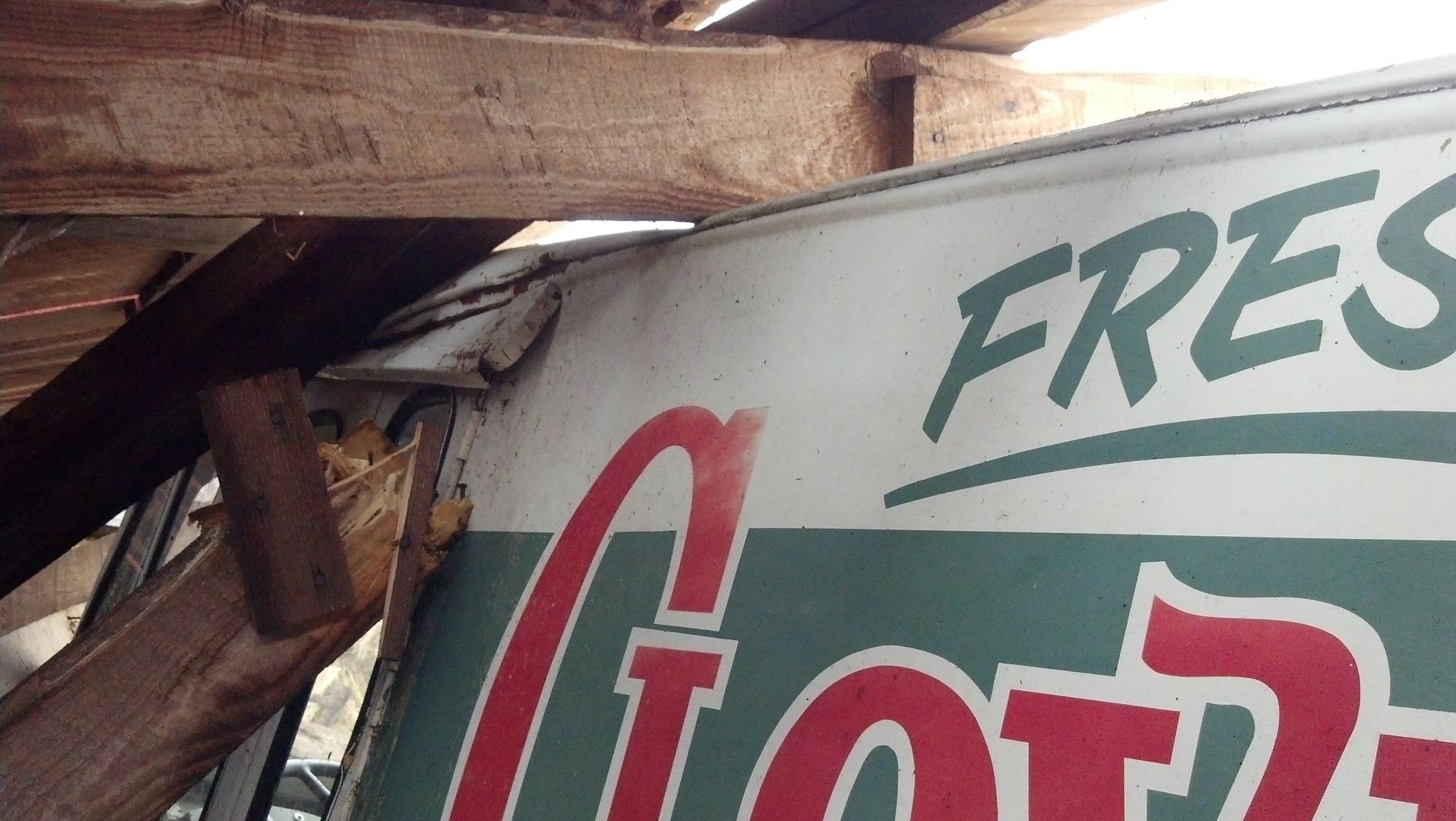
In '71, had the car fixed by an out of work body man who welded in new headlight eyebrows and quarter panels then painted the car two tone green as pictured below. (Not my car but a very close representation of the colors on my car.) Sold the '55 in late '71 to pay off the loan on the '62 Vette and is a car that has remained in our collection to this day.

Looking forward to more from you and Kyle. Bend-Shape-Cut-Fit-Weld-Planish-Grind-Repeat.
Thank you. It is most entertaining and interesting.
On the second go round of reading, more details emerge for me and the process becomes clearer and it makes me want to try my hand making some bends and welding up some panels..... Only if it were to be a reality for me since you make it looks so easy, there is very clear knowledge now, would have my hands full of very large holes blown through the metal.... Time, practice, patience, repeat might get me to the level of talent you have in your little finger.
Further, this thread brings back some very cherished memories of the first car in my life (actually a lot of "firsts" in this car), a '55 Chevy 2 door station wagon given to me from my Dad in 1967. Lots of rust, a nasty old 235Ci 6 cylinder engine with 3-speed on the tree. Did my best to patch up the rusted headlight eyebrows and quarter panels, patch up the dents (of course with bondo) and have the car painted for the $ 39.95 special. Needed to get rid of the 6 in favor of a 283 V-8 punched out .040 over to 292 and a big 4 barrel carb. Know too, replacing spider gears in the rear end became very easy for me....
In '71, had the car fixed by an out of work body man who welded in new headlight eyebrows and quarter panels then painted the car two tone green as pictured below. (Not my car but a very close representation of the colors on my car.) Sold the '55 in late '71 to pay off the loan on the '62 Vette and is a car that has remained in our collection to this day.
Looking forward to more from you and Kyle. Bend-Shape-Cut-Fit-Weld-Planish-Grind-Repeat.
Thank you. It is most entertaining and interesting.
Last edited:

larry4406
Well-known member
Nothing like having the right tools for the job and knowing how to use them! Excellent job! Keep it coming.
Some guy just never get tired of showing off their incredible metalworking skills. And I'm glad you don't.
Another beautiful panel along with great how to pics and "motion pictures".
Thanks,Robert,you never fail to teach me something new.
Mike
Another beautiful panel along with great how to pics and "motion pictures".
Thanks,Robert,you never fail to teach me something new.
Mike
jimkinney
Well-known member
Nothing like having the right tools for the job and knowing how to use them! Excellent job! Keep it coming.
Ditto, it looks so easy when you know what you are doing.
Thanks for taking the time to show us.
Jim
TimeWarpF100
Well-known member
Thanks Mike. I have a "regular" set of beading dies for the Lennox, but the lower die prevents you from crossing any other beads. This method removes that limitation.. and can be done with hand tools!
Over the Top! Project that is . .
aggierailroad
Well-known member
What a beauty. Robert, do you keep an Instagram account? I'd love to follow your feed and keep up with those snapshots as you're working.
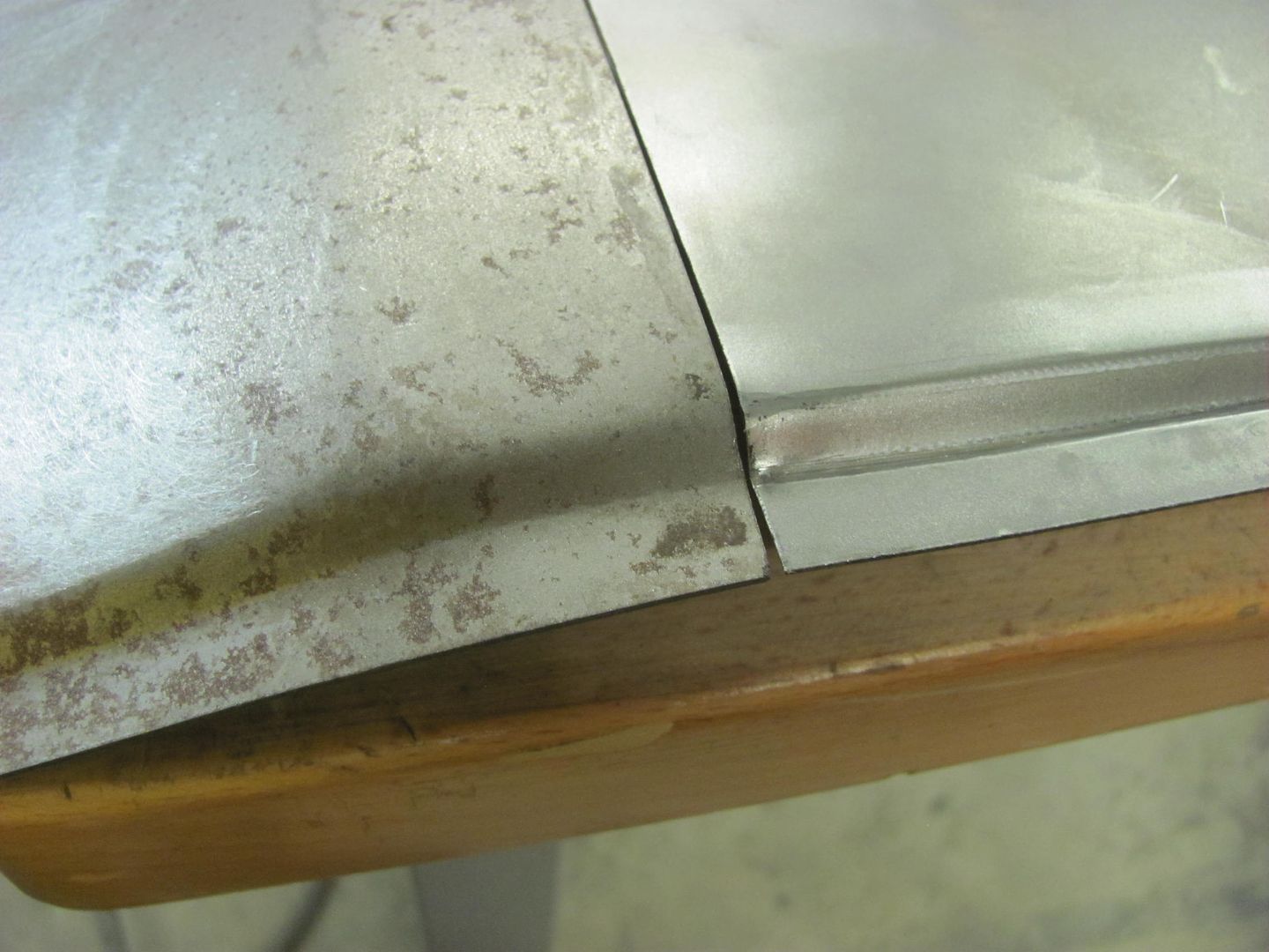
Last night we used the poster board template to check the fit of our pattern to the passenger side. Only a slight shave in the middle for a good snug fit. Then we test fit the repop front section of wheel well, which was horrendous. if we were to trim it to fit there wouldn't be enough step flange left over for the seal. So, Kyle added a 1/2" strip of 18 gauge cold rolled to the outside so we will have enough to trim for a proper fit. Still needs to add that corner on this side as well.
While he was welding away, I trimmed the second panel for the passenger rear wheel well, used the Lennox with the tipping die to add the step flange for the seal, and got it prepped for the bead detail work, which we'll get to on Saturday.
While he was welding away, I trimmed the second panel for the passenger rear wheel well, used the Lennox with the tipping die to add the step flange for the seal, and got it prepped for the bead detail work, which we'll get to on Saturday.
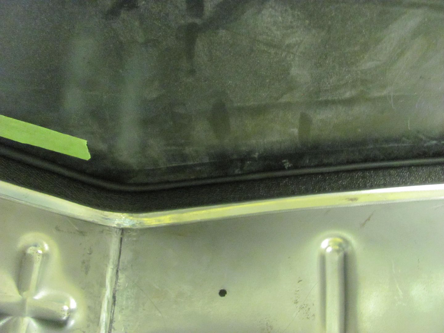
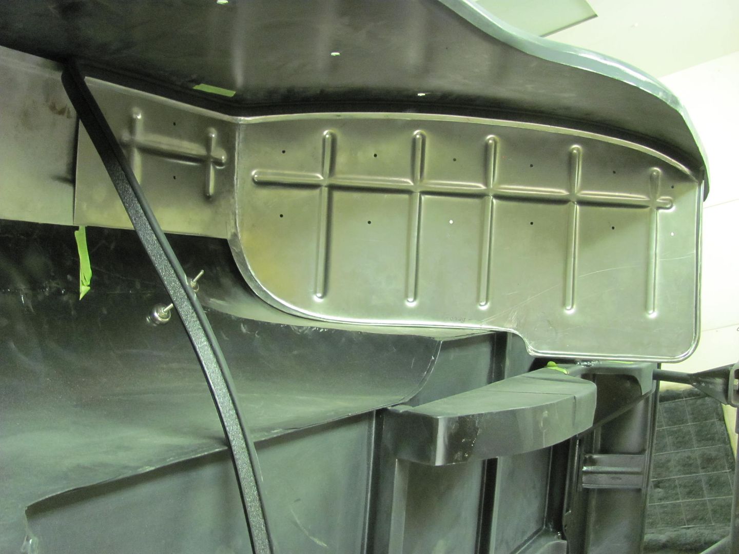
Here's a test fit of the reproduction wheel well for the 55, this is the front section. Note the poor fit to the rear side of the quarter panel. I don't know if these are an EXACT reproduction of OEM, but have heard others having similar "gaping hole" issues with their original cars.
This is the driver's side:
video version....
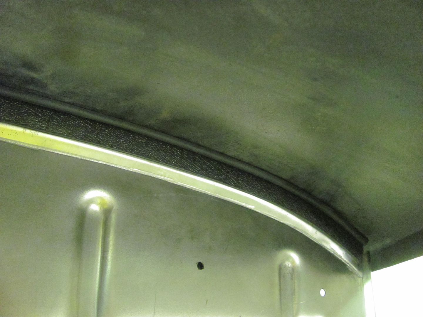
This is the passenger side we modified Thursday, adding a 1/2" filler strip and then trimming to fit to the quarter panel....
.......and shown here with seal in place...
Here Kyle is adding the 1/2" filler strip to the driver's side reproduction wheel well.
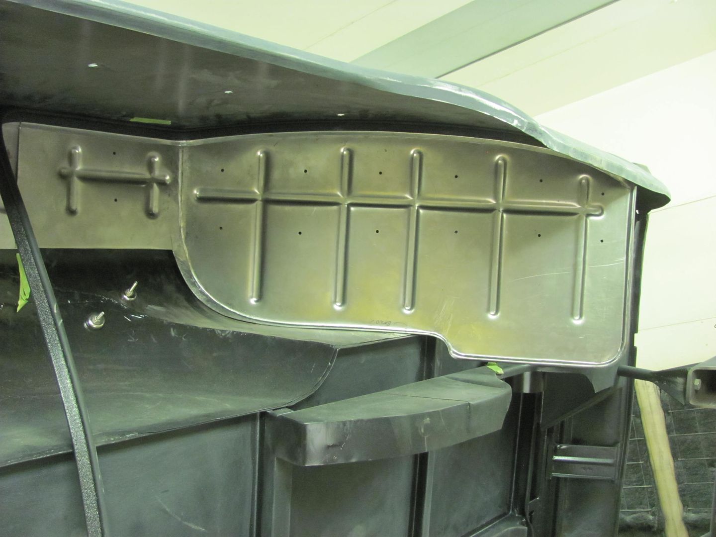
With the rear section not available in reproduction (blessing in disguise), here is the final layout and trim of our version..
Flanges are tipped using the Fasti swaging machine..
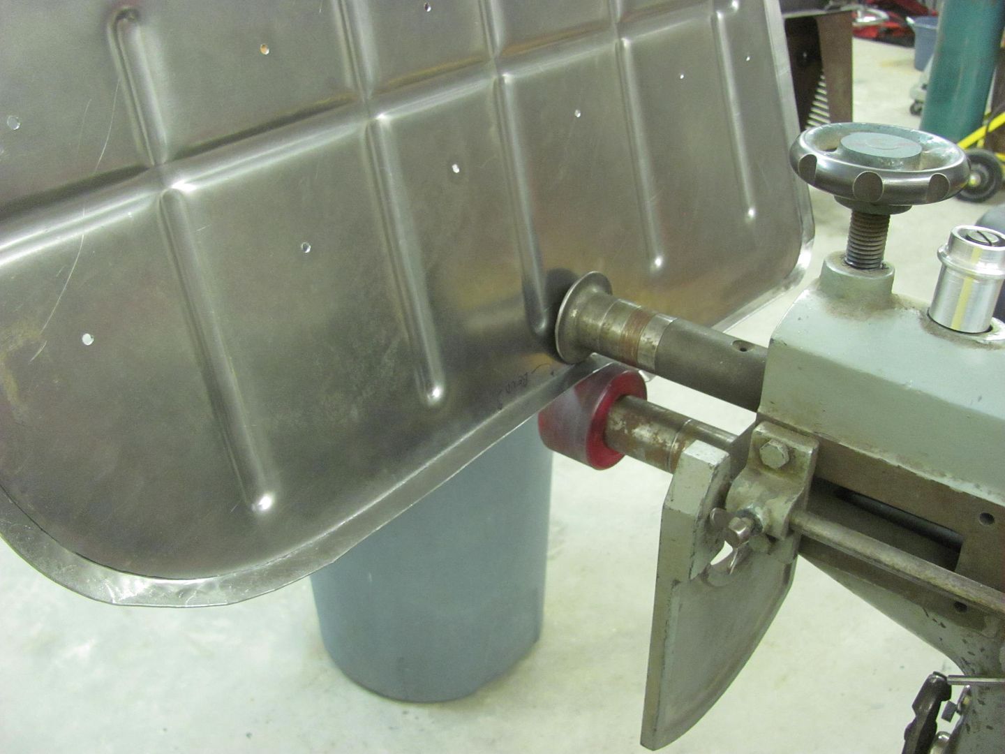
Test fit of the driver's side wheel wells. The front reproduction piece has the filler strip added but still needs trimming, the rear section is a much better fit than what came out from the factory..
Video version:
Once the front section has been trimmed for proper fit, we will **** weld the front and rear section together to eliminate another overlap rust trap.
This is the driver's side:
video version....
This is the passenger side we modified Thursday, adding a 1/2" filler strip and then trimming to fit to the quarter panel....
.......and shown here with seal in place...
Here Kyle is adding the 1/2" filler strip to the driver's side reproduction wheel well.
With the rear section not available in reproduction (blessing in disguise), here is the final layout and trim of our version..
Flanges are tipped using the Fasti swaging machine..
Test fit of the driver's side wheel wells. The front reproduction piece has the filler strip added but still needs trimming, the rear section is a much better fit than what came out from the factory..
Video version:
Once the front section has been trimmed for proper fit, we will **** weld the front and rear section together to eliminate another overlap rust trap.
Robert,
After Kyle tacks the strip he runs a nearly continuous bead with the TIG to finish it off. How come there is no warping? Is it because of a low setting on the TIG?
Heat is going to be what is needed for full penetration welds, so the heat setting isn't set to a "low setting" per se. This is a good example of what I've said previously in using body features for weld seam placement. If we were welding a quarter panel patch, I would be less concerned of using the least amount of patch possible and more with access for planishing and also what features of the panel will help to hold the weld seam from going all crazy. This normally means finding an area with a body crease or a higher crown area. In much the same fashion as an arch is used on a bridge, the shape of the wheel well helped to support its own shape. Next, even though we could have performed this weld with the MIG, the areas of starting and stopping are where you experience more shrinking. Heats up fast, cools down fast, shrinks and distorts more. Sure you can planishing to eliminate, but using the TIG with a full weld pass (or as long as possible) provides a gradual heating of the panel as you travel across, and a gradual cool down in the same fashion, as the heat stays on the panel. It isn't the quick in and out that we need to use with the MIG. Now this isn't to say you won't get shrinking and distortion with the TIG, but it is much less. Also, gaps were non-existent so no pulling of the panel during shrinkage. Basically, all aspects of the processes used MINIMIZE the distortion and shrinking effects where it wasn't as bad as you would see otherwise. We still planished the weld seam after completion. And this probably took one fourth to one third the time as had we used MIG.
Last edited: