To avoid these ads, REGISTER NOW!

Not your usual Mini-Split install

Gerald O

Well-known member
Joined
Mar 5, 2013
Messages
1,884
Location
NC
I just wanted to be a bit more comfortable working in my garage. You know-- not be soaking wet and raining sweat on everything. Last winter it was the opposite; it was all I could do to keep a grip on a wrench with my frozen fingers. I got a 5000w electric heater that I could place next to me, and that held the frostbite at bay. But all the heat would just blow right out of my well ventillated roof.

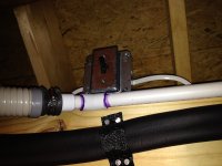
So I was determined to add a heating and cooling system. Thus began the ordeal of navigating the maze of new building codes and energy conservation regulations that don't care if you want to be comfortable in your workshop. It turns out that to be comfortable, you are required to seal the place up like a space ship and have R9zillion insulation. And of course you have to finish the interior walls, which means all that electrical and plumbing you were planning on doing someday has to be done now, before you are allowed to be comfortable.

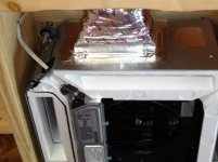
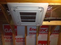
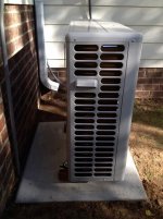
So then I set about installing all that electrical and plumbing so that I could insulate and close the walls up so that I could add a heater, except by this time it was the middle of summer and I didn't need a heater, I needed an air conditioner. The obvious solution would be a heat pump. And because mini-split heat pumps are all the craze now, because they're so easy to install, I decided that was for me too. But not just any mini-split heat pump... I would have a multi-zone system to handle both my shop and the loft above.

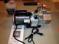
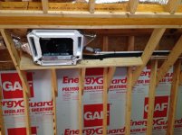
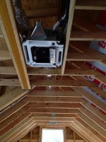
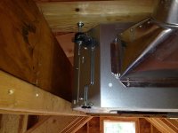
This thread doesn't bother you with all the other stuff I have had to do and still need to do, like insulation, drywall, plumbing in a new bathroom and such. This thread just chronicals my rather 'un-typical' mini-split installation.
 
To avoid these ads, REGISTER NOW!
OP
G

Gerald O

Well-known member
Joined
Mar 5, 2013
Messages
1,884
Location
NC
First off, selecting a system configuration had to take into account the sloped ceiling of my over-the-garage loft. It doesn't have any good locations for a wall mounted indoor unit. The ceiling has a flat area though that runs the entire length, so a ceiling cassette unit was the nicest solution. I found a reasonable deal on a Friedrich 24Kbtu multi-zone heat pump with a pair of 12K BTU ceiling cassette evap units. One cassette would be for the downstairs garage-shop and one for the attic loft.

I purchased the equipment from acwholesalers.com (though I would not necessarily recommend them).

PC43051-lg.jpg


It turns out that this Friedrich system is actually re-badged LG equipment. This was a 2014 model. The condenser unit is Model# MR24DY3JM, and the ceiling cassettes are Model# MC12Y3JM
 
Last edited:
OP
G

Gerald O

Well-known member
Joined
Mar 5, 2013
Messages
1,884
Location
NC
I waited for about a month to receive my equipment that was supposedly in-stock when I ordered it, but turned out to actually be "back-ordered" at the factory. I think acwholesalers doesn't actually stock what they sell, they place orders with the factory and it gets drop shipped to you. But it arrived in good shape and the delivery guy wheeled the pallet right up to my door.

attachment.php


Unfortunately, after opening the boxes, I discovered that the cover grills for the cassette air handlers were not included. They are pictured with covers, and you are not told that you have to order those separately at extra cost. Why? The units are useless without the grilles which contain the remote control thermostat circuitry. I think its just a scam to make the up-front price appear lower.

So I waited another month for acwholesalers to ship me my grilles--they were back ordered too...(despite being listed as in-stock). No problem, I had parts to get started while I was waiting.
 

Attachments

  • mshp_01.jpg
    mshp_01.jpg
    79.8 KB · Views: 3,085
Last edited:

fireant911

Well-known member
Joined
Dec 22, 2012
Messages
51
Location
Alabama
Gerald O,
I will be following this thread closely because phase II of our heating and cooling project MAY involve cassette units. Our installer recommended for us to steer clear of those and only use wall-mounted units??? My wife is adamant about not installing those ugly (her words) wall-mounted units in the sunroom but since I know nothing about the cassette types I am hesitant to make the leap.

There were literally hundreds of cassette units installed at my previous work place and they seemed to do a good job; however, the existing central air was also running concurrently (oftentimes one unit was in heating mode while the other unit was in cooling...) We never could convince the maintenance staff that a problem existed with running both systems in opposing modes (it was government work so little attention was given to efficiency).

We installed two wall-mounted Fujitsu's this summer and they perform wonderfully. I am quite interested in the performance you achieve from the cassette units. How is the condensation drainage handled (gravity, condensate pump, etc...)? All of the cassette we looked at seemed to have lower SEER ratings and carry a larger price tag as compared to an equivalently sized wall-mounted system.
 
OP
G

Gerald O

Well-known member
Joined
Mar 5, 2013
Messages
1,884
Location
NC
I unpacked the equipment right away while the shipper was present to check for any shipping damage. Everything looked good!
I confirmed that the condenser unit looked nothing like the picture on the seller's website, but I was already prepared for that having visited the Friedrich web site and downloaded the brochures and manuals.
attachment.php


I also confirmed that the system is rated with very good efficiency rating--
attachment.php


The refrigerant coil fins are quite visible and are plated with some kind of shiny gold colored finish. Friedrich (and LG) call this "GoldFin anti corrosion".
attachment.php


The condenser will support up to 3 indoor units to a total of 24K BTU total system output. There are separate fittings for each of the 3 indoor units, but only one set of service valves. More on that later.
attachment.php
 

Attachments

  • mshp_02.jpg
    mshp_02.jpg
    64 KB · Views: 3,020
  • mshp_03.jpg
    mshp_03.jpg
    118.2 KB · Views: 3,022
  • mshp_05.jpg
    mshp_05.jpg
    71.8 KB · Views: 3,016
  • mshp_04.jpg
    mshp_04.jpg
    133.6 KB · Views: 3,002
Last edited:
OP
G

Gerald O

Well-known member
Joined
Mar 5, 2013
Messages
1,884
Location
NC
Gerald O,
I will be following this thread closely because phase II of our heating and cooling project MAY involve cassette units. Our installer recommended for us to steer clear of those and only use wall-mounted units???
Probably because they are more difficult to install, as you will see...

How is the condensation drainage handled (gravity, condensate pump, etc...)?
They have built-in condensate pumps that can lift up to 24" or so.
All of the cassette we looked at seemed to have lower SEER ratings and carry a larger price tag as compared to an equivalently sized wall-mounted system.
I suppose they are not the highest SEER available, but I think 21.7 is still pretty respectable. Though I think that is best case. It depends on what air handler combination is used. It may drop to 19 or so with the two 12K cassettes. Still, the heat pump to my house is only rated at about 14.5 SEER.
 

CWO4GUNNER

Well-known member
Joined
Aug 17, 2014
Messages
229
Location
BHC AZ
Congratulations everything is intact. I hate to hear about those sales tactics but at least your stuff looks new and undamaged. Please do go into detail on the cassette install as you may change my mined on the ugly wall mounted unit lol.
 
OP
G

Gerald O

Well-known member
Joined
Mar 5, 2013
Messages
1,884
Location
NC
Here is the pad preparation. Now this part is pretty generic, but a lot of minis are being installed with wall brackets. I thought about that, but decided I didn't want the possibility of hearing any vibrations transmitted into the walls.

First I prepared a simple form about 2' x 3' square. It took about 5 bags of quick-crete. I dusted off my seldom used 3 cuft Harbor Freight cement mixer for the task. Perfect size for the job! Red bricks with holes were placed to create elevated locations to mount the condenser unit.
attachment.php


Unfortunately, I discovered the next day that I had mis-positioned the pad. I ended up having to move the 350 lb slab over about a foot. Ughhh!

I drilled the slab for 1/2" x 6" concrete expansion bolts and set these in quick-setting anchor bolt cement, also filling the holes in the bricks with it. Sections of SuperStrut were bolted down to form the mounting rails. I should have used the taller SuperStrut, but I already had this low profile stuff on hand.
attachment.php
 

Attachments

  • mshp_08.jpg
    mshp_08.jpg
    87.6 KB · Views: 2,951
  • mshp_06.jpg
    mshp_06.jpg
    100.2 KB · Views: 2,945
OP
G

Gerald O

Well-known member
Joined
Mar 5, 2013
Messages
1,884
Location
NC
A General Electric AC disconnect was mounted to the wall where the wires would pass through from the garage. This particular disconnect also has a built-in GFCI receptacle. Handy to have power to plug tools into while woking on the AC unit.
attachment.php


The Condenser unit is bolted to the SuperStrut with the rubber pads that came with it. They don't provide much extra metal on the mounting lugs though, so part of the rubber pad hangs out.
attachment.php


About 1 foot of clearance behind to the wall, as required by the manual.
attachment.php
 

Attachments

  • mshp_07.jpg
    mshp_07.jpg
    53.3 KB · Views: 2,924
  • mshp_09.jpg
    mshp_09.jpg
    68.5 KB · Views: 2,923
  • mshp_10.jpg
    mshp_10.jpg
    70.3 KB · Views: 2,930

Syberia

Well-known member
Joined
Jan 13, 2014
Messages
1,451
Location
Perris, CA
I'll be following this as well. Considering a mini-split for part of the house but don't know if I have the balls to install it myself.
 
OP
G

Gerald O

Well-known member
Joined
Mar 5, 2013
Messages
1,884
Location
NC
Here's where things got more complicated. This was not to be a simple 'hole through the wall' installation. This would be a fully recessed installation, meaning the ceiling framework has to be customized. This roof doesn't have much spare space above the ceiling, but it would be enough.
After a bit of head-scratching, I decided on a much larger opening than the unit itself needs. The left over opening space will be tuned into a ceiling access hatch area--I had to have one somewhere...

First job was to cut the 2x6 collar ties to make the rough opening. I added a 2x10 header on the one cut side, and there was already an LVL beam of the same height on the other side (part of my dormer framing). If this were a simple peaked roof at this location then I would have run two 2x10 headers. A 2x10 gives just the right depth to fully recess the ceiling cassette unit.

There is a lot going on here that I will explain later.
attachment.php


attachment.php
 

Attachments

  • mshp_11.jpg
    mshp_11.jpg
    71.7 KB · Views: 2,889
  • mshp_12.jpg
    mshp_12.jpg
    64.4 KB · Views: 2,900

theoldwizard1

Well-known member
Joined
Feb 22, 2011
Messages
43,076
Location
SE MI
I waited for about a month to receive my equipment that was supposedly in-stock when I ordered it, ...

Strike 1 !

Unfortunately, after opening the boxes, I discovered that the cover grills for the cassette air handlers were not included. They are pictured with covers, and you are not told that you have to order those separately at extra cost.

Strike 2 !

So I waited another month for acwholesalers to ship me my grilles--they were back ordered too...(despite being listed as in-stock).

Strike 3 ! You're out !!

I have to remember to never order from them !!
 
OP
G

Gerald O

Well-known member
Joined
Mar 5, 2013
Messages
1,884
Location
NC
Strike 1 !

Strike 2 !

Strike 3 ! You're out !!

I have to remember to never order from them !!
Just take a look at their BBB record...

But they sold the equipment I wanted at the best price. Roll the dice, dance with the devil.
 
OP
G

Gerald O

Well-known member
Joined
Mar 5, 2013
Messages
1,884
Location
NC
When is a ductless mini-split not ductless?

Now you may be wondering, "what are those duct looking things he's got on there? I thought these minis were supposed to be ductless!"
Well, yes and no. The ceiling cassettes can be used without adding ductwork. But they do have a provision for adding extension ducts if you want to. There are knockouts on the sides of the unit that open up passages for external ducting. I didn't find any specifications that tell what external ducting is recommended; I guess it is up to the installer to figure that out.

I could have used the ceiling cassette without any ducting, but I have a separate bathroom in the loft, and I was worried that it would not be adequately heated in the winter. I could leave the door open, but since this unit can have ducts fitted, I figured why not. Then, once I decided to go down that road, I considered that the far end of the loft might get a wall someday to create a separate room. So it should get its own vent as well.

All of this added a lot of complexity to what could have been a simpler job. So I'm sharing the details to make it easier for someone else to do something similar.

Because of the shallow space available above the unit, I went with 45deg duct boots to adapt 4" diameter flex duct to the sides of the cassette casing over the cutouts. I bent the edges out to form flanges for attachment, then attached with 4 sheetmetal screws and sealed under the flanges with mastic. Finally the flanges were sealed again to the case with aluminum tape.
attachment.php
 

Attachments

  • mshp_13.jpg
    mshp_13.jpg
    65.4 KB · Views: 2,825
OP
G

Gerald O

Well-known member
Joined
Mar 5, 2013
Messages
1,884
Location
NC
The basic mounting of the unit was accomplished with a fairly simple arrangement: two 2x4s span the headers to create suspension supports. 5" long 1/4-20 thread carriage bolts drop down through the top to provide height adjustable suspension. I added rubber vibration isolation to the mounting points. These were not provided, I made them from extra car shock absorber rubbers that I already had in the junk collection.

After the cassette is hung and leveled, the unit can be squared up and centered. Then finally the 2x4 supports are fastened to the headers once the correct position is establish.
attachment.php


attachment.php
 

Attachments

  • mshp_15.jpg
    mshp_15.jpg
    143.3 KB · Views: 2,797
  • mshp_14.jpg
    mshp_14.jpg
    120.6 KB · Views: 2,796
OP
G

Gerald O

Well-known member
Joined
Mar 5, 2013
Messages
1,884
Location
NC
If you are going to install ducts, better do it right so that you don't throw away all that efficiency promised by your mini-split. I used 4" insulated flex duct with R8 insulation. This stuff works very well if done right; if done wrong it can work very poorly.

You want to accomplish two things: minimal air flow resistance, and no leakage. For the optimal air flow the flexible inner core of the duct needs to have a straight run and needs to be stretched out to full length so that the inside is a smooth surface. Typically this stuff will be installed with all kinds of curves, kinks, and leaks. Instead of bending the flex duct where it transitions down to the ceiling vents, 90deg metal elbows should be installed on the vents, and the flex duct should run straight to the elbow.

Seal the flex duct core to the elbow duct with mastic, then fasten with a band clamp or appropriate heavy-duty zip tie. Wrap that with duct tape, then refit the insulation over the flex an the elbow. Tape it again and secure with a second zip tie. All the joints in the elbow must also be made air tight. I used aluminum HVAC tape to seal these joints.
attachment.php


attachment.php


attachment.php


attachment.php


attachment.php
 

Attachments

  • mshp_20.jpg
    mshp_20.jpg
    64.5 KB · Views: 2,775
  • mshp_17.jpg
    mshp_17.jpg
    70.3 KB · Views: 2,771
  • mshp_16.jpg
    mshp_16.jpg
    67.1 KB · Views: 2,784
  • mshp_34.jpg
    mshp_34.jpg
    75.6 KB · Views: 2,779
  • mshp_33.jpg
    mshp_33.jpg
    68.3 KB · Views: 2,781

CWO4GUNNER

Well-known member
Joined
Aug 17, 2014
Messages
229
Location
BHC AZ
I hope the cassette has enough static pressure to carry through a 4" duct, especially if (like it looks) it is branching off to the loft. I hope it works and settles that debate concern.:thumbup:

PS...Thanks for all the great detail which is going to help alot of us DIY installers save big! Huge thank you and please continue the detail.
 
Last edited:
OP
G

Gerald O

Well-known member
Joined
Mar 5, 2013
Messages
1,884
Location
NC
I hope the cassette has enough static pressure to carry through a 4" duct,
Hence the importance of minimizing the flow obstructions and keeping the runs as straight as possible.
especially if (like it looks) it is branching off to the loft. I hope it works
Not sure what you mean by branching, this is the loft install. The cassette is in the center of the loft, and there are two 10' ducts extending in opposite directions, one terminating in the bathroom and one at the opposite end of the loft. The cassette itself draws air in at its center through a filter in the grille. It then blows through the evaporator coil and out, axially, into the side chambers of the cassette. Without the added ducts, all the conditioned air would flow down and out through the 4 louvered ducts on the bottom outside edges of the cassette. These outlet louvers are motorized, by the way. They slowly wave back and forth to help distribute the output air.

With the addition of the branch ducts, the total airflow still goes into the loft, but it is divided between the branches and the cassette louvers. There is definitely airflow through all. My main objective is to better distribute the air and to get some positive airflow into the bathroom.
PS...Thanks for all the great detail which is going to help alot of us DIY installers save big! Huge thank you and please continue the detail.
Thanks! I hope it will be helpful, but this is not a trivial job. It might help someone save money by doing it themselves, or it might help them decide that this job is too tough for them and to hire a pro. In my opinion though, a pro would charge a hefty price for this job; I know I would. The price of labor would likely be more than the price of the equipment.
 
Last edited:
To avoid these ads, REGISTER NOW!
OP
G

Gerald O

Well-known member
Joined
Mar 5, 2013
Messages
1,884
Location
NC
The line set for this unit needed about a 40' run from the outside unit. The closest size lines carried by the seller were 50'. Since I had plenty of extra length, I went ahead and cut off the factory tubing flares and remade them using the flare nuts from the equipment. The ones that come on the heat pump are more heavy duty. Also, the factory flares had ridges and scratches; mine are are better. When attaching the flare nuts, I used Nylog blue sealant to lubricate and better seal the connection.
attachment.php


This was to be a fully enclosed installation--no lines exposed on the wall surface. I started the routing of the lines at the cassette unit and fed them toward the outside unit. First they route through the roof area toward the end (gable) wall. The condensate drain is 3/4" PVC pipe. This needs to have a constant gradual slope downward toward the outside of about 1/8" per foot or better. So it needed to be securely fastened to spacer blocks at the appropriate heights to maintain the proper slope along the entire hroizontal run. The refrigerant lines just lay on the top of the ceiling joists and route generally straight and level. The power cable to the indoor unit also runs along this route. I used 14-3 romex with ground.

attachment.php


attachment.php
 

Attachments

  • mshp_35.jpg
    mshp_35.jpg
    117.4 KB · Views: 1,645
  • mshp_22.jpg
    mshp_22.jpg
    116.3 KB · Views: 1,651
  • mshp_18.jpg
    mshp_18.jpg
    53.6 KB · Views: 1,649
OP
G

Gerald O

Well-known member
Joined
Mar 5, 2013
Messages
1,884
Location
NC
At the gable wall the lines need to take a 90 deg turn straight down where they will drop inside the wall to the lower level. There needs to be fire-blocking at the top of the wall cavity, but I didn't want to try snaking the refrigerant lines all the way down through that little hole while continually bending it through a sharp 90. So I pre-made the block piece with holes in it and threaded it loose onto the lines, leaving it unfastened. This way I was able to swing the lines downward while feeding them through the ceiling and wall with a long relaxed bend near the wall until the whole thing was routed into position. Then, with the lines at their final position, after I attached them at the cassette, I knew right where the 90 deg bend would be so I could then make that bend once and then nail the fire-block piece into position.

attachment.php


attachment.php
 

Attachments

  • mshp_23.jpg
    mshp_23.jpg
    58.7 KB · Views: 1,632
  • mshp_24.jpg
    mshp_24.jpg
    64.2 KB · Views: 1,638
OP
G

Gerald O

Well-known member
Joined
Mar 5, 2013
Messages
1,884
Location
NC
Great job. Very clean install. You should insulate the metal boots or they will sweat.
Thanks. Very true, the metal duct boots will get insulated. I'll post a photo when that gets done.
There are also a few other things that remain to be insulate: the ends of the refrigerant lines, and I may add more insulation to the cassette unit itself, because this can be a very humid climate in my area during the cooling season.
 

Jackfre

Well-known member
Joined
Dec 26, 2010
Messages
4,406
Location
N CA
Nice install. A couple things. The reason to use the wall bracket is to give more ground clearance in the heating defrost mode. This may not be as big a deal in NC, but in Maine I've seen ice build up freeze up the whole lower section of the condensing unit. The new Super low temp units actually have heated drain pans to prevent this. The brackets come with vibration isolators and with two units mounted on a bedroom wall there is no vibration.

One of my favorite pitches about the "ugly wall hung" units was to say the the "longer you live with them, the better looking they become". I had a number of contractors come back to me saying their wives felt as your does, but that within a week, the objections ceased.

I would suggest that you buy a 90* angle boot and eliminate straight boot the additional 90 and rising duct.

Nice install! I'm sure you will be very comfortable.
 

ambenz

Well-known member
Joined
Dec 12, 2010
Messages
4,236
Location
NW Chicago Suburbs
Great build and documentation.
I have to say, if you did not do this yourself, a contractor would NOT put the effort in to keep the ducting taught, the insulation tight and clean, and the piping true.
Contractors know time is money and most installers just want to get it done and get home before rush hour starts.
I am a automation HVAC tech and in all my years automating VAV's and FPB's, the sheetmetal workers just slap it up in a hodgepodge fashion.
So, there is something to be said for doing it yourself!!!!
You know it was done right and you know where every potential problem might be if there ever becomes a issue in the future.
Kudo's for doing it yourself...the piece of mind knowing it was done right, is priceless!!!!

PS: Too bad you had to place the exhaust fan so close to the HVAC discharge vent in the bathroom....that's gonna **** the discharge when in use....maybe a auto damper to close the discharge when the exhaust is on, might be in order?!?!

attachment.php
 
Last edited:

CWO4GUNNER

Well-known member
Joined
Aug 17, 2014
Messages
229
Location
BHC AZ
Great build and documentation.
I have to say, if you did not do this yourself, a contractor would NOT put the effort in to keep the ducting taught, the insulation tight and clean, and the piping true.
Contractors know time is money and most installers just want to get it done and get home before rush hour starts.
I am a automation HVAC tech and in all my years automating VAV's and FPB's, the sheetmetal workers just slap it up in a hodgepodge fashion.
So, there is something to be said for doing it yourself!!!!
You know it was done right and you know where every potential problem might be if there ever becomes a issue in the future.
Kudo's for doing it yourself...the piece of mind knowing it was done right, is priceless!!!!
attachment.php

Truthfully and so very well said, becasue with knowledgeable and effective DIY installation the conflict of interest is eliminated. ;)
 
OP
G

Gerald O

Well-known member
Joined
Mar 5, 2013
Messages
1,884
Location
NC
Nice install. A couple things. The reason to use the wall bracket is to give more ground clearance in the heating defrost mode. This may not be as big a deal in NC, but in Maine I've seen ice build up freeze up the whole lower section of the condensing unit.
Yeah, I understand how that could be a problem in snowy regions. In my area it rarely snows more than a couple inches and it melts within a couple days. Temperatures rarely get below 20F in the winter. I've got about 4" of clearance. That'll do.
 
OP
G

Gerald O

Well-known member
Joined
Mar 5, 2013
Messages
1,884
Location
NC
Great build and documentation.
I have to say, if you did not do this yourself, a contractor would NOT put the effort in to keep the ducting taught, the insulation tight and clean, and the piping true.
Contractors know time is money and most installers just want to get it done and get home before rush hour starts.
I am a automation HVAC tech and in all my years automating VAV's and FPB's, the sheetmetal workers just slap it up in a hodgepodge fashion.
So, there is something to be said for doing it yourself!!!!
You know it was done right and you know where every potential problem might be if there ever becomes a issue in the future.
Kudo's for doing it yourself...the piece of mind knowing it was done right, is priceless!!!!
Thanks! I did have the building shell built by a contractor, though I designed it and drafted all the plans. It was painful and aggravating at times watching the builders screw things up and having to get after them to do it right. There were things I wanted done a particular way and they just either couldn't understand it or just ignored me. I was on the verge of firing them more than once. I think most builders don't usually have to answer to a knowledgeable and experienced customer. It came out Ok though. I'm afraid if I built the thing myself it would take me years. Finishing the inside is all on me though. But at least I can take my time and have it the way I want.

PS: Too bad you had to place the exhaust fan so close to the HVAC discharge vent in the bathroom....that's gonna **** the discharge when in use....maybe a auto damper to close the discharge when the exhaust is on, might be in order?!?!
Yeah, I thought about that. The horizontal part of the bathroom ceiling is very small, about 2x7. Most of it is sloped. When I originally positioned the fan I hadn't planned on having a vent duct in the bathroom. Truth is that the bathroom fan will probably be rarely used. It has to have one for code.
 
Last edited:
OP
G

Gerald O

Well-known member
Joined
Mar 5, 2013
Messages
1,884
Location
NC
More details.
The refrigerant lines, a control cable, the condensate line, and the 220v power for the outside exit through the gable end wall of the garage just above the foundation. I used a 2" PVC pipe coupling as the refrigerant line pass-through. It is sealed against the weather on the inside and outside with silicone seal, as is the 3/4" condensate line.
attachment.php


To make this bend in the refrigerant lines from vertical to horizontal where it exits the wall required that all the routing above up to the indoor units was completed. This is a fairly tight radius bend and the lines shouldn't be bent this much more than once. So it needed to be in the exact spot the first time. The lines hadn't been cut to final length at this point, and there was about 10' of excess line. So I made a fairly large loop in the free end to feed it through the hole in the wall with minimal stress on the lines. Then as it got close to the final position I was able to start tightening up the bend radius.

The electrical passes through a short conduit fitting into the back of the AC disconect mounted outside. 220v power is carried on #12-2 wire with ground. This unit requires about 15A and the circuit is protected with a 20A breaker. A separate #12 cable carries 120v to the GFCI service outlet contained in the AC disconnect box.
attachment.php

Inside the disconnect box the NM cable transitions to THHN stranded for the run though the flexibile conduit. The smaller conduit carries the 220V main power, and the larger conduit carries the power and signal wires to the indoor unit. I wanted to have room for adding more wires for more indoor units.
attachment.php


On the outside, the refrigerant lines are protected as much as possible by a length of 2" PVC pipe. It is not glued into the wall fitting. I added a trap to the condensate line to help keep critters out. It is not glued either.
attachment.php


All the connections have been completed for the upstairs unit now.
attachment.php


Here's where someone might start wondering, "I thought this was going to be a multi-zone intallation?" It was. Then I discovered that the new energy conservation regulations don't allow me to heat or cool my garage unless the concrete slab floor is insulated. Lets just say I won't be adding the 2nd cassette unit in the garage...at this time (cough). I'm doing this under permits and it will be inspected by the building inspector. Who knows what people read these forums...?

If I 'were' to add it though it would have another set of refrigerant lines, a control cable, and another condensate line. These would be surface mount rather than run inside the walls. ;)
 

Attachments

  • mshp_29.jpg
    mshp_29.jpg
    125.7 KB · Views: 1,483
  • mshp_27.jpg
    mshp_27.jpg
    64.7 KB · Views: 1,494
  • mshp_28.jpg
    mshp_28.jpg
    75.4 KB · Views: 1,497
  • mshp_26.jpg
    mshp_26.jpg
    54.1 KB · Views: 843
  • mshp_25.jpg
    mshp_25.jpg
    72.6 KB · Views: 838
Last edited:
OP
G

Gerald O

Well-known member
Joined
Mar 5, 2013
Messages
1,884
Location
NC
The indoor unit gets a 3-pole switch to serve as the disconnect. This system sends 220v to the indoor unit over two conductors and has a third conductor carrying a control signal. So all three wires get disconnected with this switch. It's actually a 30amp motor rated switch, and the cassette draws very little current, but it will do.
attachment.php


Since I used 14-3 romex, I used the black and the red wires for the 220v L1 and L2. The control signal is carried on the white wire, which needed to be recolored. I chose blue. A blue permanent sharpie marker does the job. This color is also duplicated at the other end of the cable inside the outdoor disconnect.
attachment.php
 

Attachments

  • mshp_19.jpg
    mshp_19.jpg
    139.6 KB · Views: 1,465
  • mshp_21.jpg
    mshp_21.jpg
    52.1 KB · Views: 1,466
OP
G

Gerald O

Well-known member
Joined
Mar 5, 2013
Messages
1,884
Location
NC
The Cassette cover grille has motorized louvers and the remote control receiver for the handheld thermostat remote. So it was necessary to plug in three separate connectors. These plug into connectors on a circuit board under the electrical box cover. They are color coded so it was easy to see where each connector went.
attachment.php


Now it was time for the dry run test! I screwed the grille into place, turned on all the disconnects, went to the breaker panel to switch on the breaker, and held my breath...

I flipped the breaker on and...


attachment.php


There were no sparks no smoke and no explosions!

I went outside to check the condenser unit, it was doing its power on self test, making a few clicking sounds, a few humming sounds and then settled down. I went upstairs, put the batteries in the remote, and pressed the ON button. The power LED illuminated, remote indicated the indoor temperature and the settings, and the louvers on the grill rotated. Then, since the refrigerant has not yet been released, I pressed the FAN button to put the fan on manual. The fan turned on and I could cycle through the various fan speeds. I checked airflow at all the vents and it seemed adequate. Yay!!

attachment.php


Now, all that remains for this "phase 1" install is to evacuate the lines and leak test, then to release the refrigerant. Rather than trying to find someone willing to service my DIY install, I ordered new HVAC tools for that task which should be arriving next week. I figure that the tools will quickly pay for themselves.
 

Attachments

  • mshp_32.jpg
    mshp_32.jpg
    59.8 KB · Views: 1,461
  • mshp_30.jpg
    mshp_30.jpg
    114.3 KB · Views: 1,604
  • mshp_31.jpg
    mshp_31.jpg
    56.8 KB · Views: 1,466
Last edited:

CWO4GUNNER

Well-known member
Joined
Aug 17, 2014
Messages
229
Location
BHC AZ
Good for you! The tools will not only pay for themselves but in time probably for all the equipment as well. I do recommend positive pressure testing with nitrogen though as a deep vacuum is not a mothod of determining a leak but rather just to remove air & moisture. But I'm sure you already know that. Did you happen to mention how many BTU the outside unit is?

I wanted to add that you helped me realized in my own quest for the search, application and installation of my own mini-split system how cost effective it may be to invest in a separate multi-zone outside unit even if your not going to just going to use its total potential and purchase just 1 large sized wall unit/cassette based initially on your current needs and applicability, saving money. This providing later scalability which possible should the need arise later, and in my case with different rental unit configurations making it a better choice IMO. After searching the internet for the single zone unit I though I had settled on, I must say that your purchase seemed most appealing and stopped me in my tracks for reconsideration. All except for the issue of the incomplete cassettes components and extra charges you incurred not including the grill circuitry.

So I decided to write the supplier an email and question my concerns frankly and honestly from strictly a original standpoint of course, this way I would have it in writing from both their sales and corporate offices. Iv decided to honor the privacy of their email response for email sake and just say that their response basically laid out in writing by serial number that both the 24K OD unit and 18K ID unit. ("The Friedrich Model MR24DY3JM item# 43051 is a brand new condensing unit, not used or refurbished from the manufacture, without any missing internal parts that have separated as accessories. The Friedrich Model MC18Y3JM Item# 43048 comes complete with the air handler and the grill for the cassette which contains the thermostat circuitry as an all one unit. Both items are in stock and ships with 2 to 3 business days.") So I think with this email documentation I may also take a chance at those prices.
 
Last edited:
OP
G

Gerald O

Well-known member
Joined
Mar 5, 2013
Messages
1,884
Location
NC
Tools have arrived!

This will be the minimum set of tools I'll need to evacuate the lines and get the system running.
attachment.php


You could normally get by without the manifold gauge set if only evacuating, but you still need at least one charge line to connect to the vacuum pump. However I've got to pump the refrigerant back down later when I install a second indoor unit, and I'll need the full gauge set for that. This set is designed for heat pumps. Both gauges go to 800 lbs to be able to handle the system switching from cooling to heating mode and to handle the higher R410A pressures.
attachment.php


5/16" to 1/4" flare adapters are needed for connecting the R410A mini split service valves to standard 1/4" charge lines.
attachment.php


A digital vacuum gauge is needed to be able to measure the deep vacuum levels required by the mini split. This CPS gauge comes with a nice carry pouch, a T fitting, and a hanging hook.
attachment.php


This Yellow Jacket vacuum pump is a beast! 1/2 horsepower, and rated to pull a 15micron vacuum. This one is 4 CFM. They make bigger ones in this series, but this one will do for my purposes.
attachment.php


I like that it has a 2-Year warranty and is Made in USA.
attachment.php
 

Attachments

  • mshp_36.jpg
    mshp_36.jpg
    62.1 KB · Views: 1,365
  • mshp_39.jpg
    mshp_39.jpg
    66.8 KB · Views: 36
  • mshp_40.jpg
    mshp_40.jpg
    71.5 KB · Views: 1,363
  • mshp_37.jpg
    mshp_37.jpg
    57 KB · Views: 1,358
  • mshp_38.jpg
    mshp_38.jpg
    54.5 KB · Views: 1,358
  • mshp_41.jpg
    mshp_41.jpg
    54.1 KB · Views: 1,359
  • mshp_42.jpg
    mshp_42.jpg
    59.9 KB · Views: 1,357

CWO4GUNNER

Well-known member
Joined
Aug 17, 2014
Messages
229
Location
BHC AZ
I'm very interested to see how your multi-zone operates with just 1 cassette at 50% capacity of the outside unit. Oh I see you already have 2 cassettes installed, its the 3rd your talking about installing later. Correct my last, 75%..

Hope the best results for you. :D
 
Last edited:

CWO4GUNNER

Well-known member
Joined
Aug 17, 2014
Messages
229
Location
BHC AZ
Initially I was also planning to skip the nitrogen pressure test and after performing a deep vacuum to remove air and moisture (no good for leak testing), just use the system pressure refrigerant to conduct the leak test. But I remembered that if a leak is discovered that requires the replacement or re-flair of a fitting, I would have to release (not pump down) the refrigerant in the line set as to do so would **** air into the system. Not to mention compromise the critical charge loss in the line set that would be lost. Pressure testing with nitrogen for leaks just makes sense because if a bad or complicated leak is detected in the line-set, its no big deal to release, repair and start over again until the line set and ID unit are tight, right and ready for OD unit charge release.
 
OP
G

Gerald O

Well-known member
Joined
Mar 5, 2013
Messages
1,884
Location
NC
Those are top notch professional tools ! Planning on going into business ?

Not planning on going into business, but I still want a professional quality installation. In researching the tools I learned that the bargain priced stuff was of questionable performance and quality--lots of disappointments. I like having high quality tools where it counts. This is one of those situations. I figure that I'll break even on the price of these compared to the avoided cost of only two or three basic service calls from a pro. I know that I would need at least two service calls for this installation alone since I'm not installing the 2nd indoor unit right away.

I can use the gear for working on other equipment too; my other heat pumps for the house, car AC, vacuum bagging molds, etc. Or, I can resell this gear and recoup a major portion of my investment. Cheaper gear does not maintain its resell value as well as the Yellow Jacket products.
 
Last edited:
OP
G

Gerald O

Well-known member
Joined
Mar 5, 2013
Messages
1,884
Location
NC
Initially I was also planning to skip the nitrogen pressure test and after performing a deep vacuum to remove air and moisture (no good for leak testing), just use the system pressure refrigerant to conduct the leak test. But I remembered that if a leak is discovered that requires the replacement or re-flair of a fitting, I would have to release (not pump down) the refrigerant in the line set as to do so would **** air into the system.
The evacuation procedure will reveal any leaks that would show up at low pressure (14psi atmospheric). I estimate that any leaks not detected at this stage would have a very low leakage rate under system pressure. I'll follow up with a soap bubble test under system pressure.

I think that the small risk of a leak is a reasonable trade off for avoiding the cost of the nitrogen pressure test equipment. This is my reasoning:
1) I have a high confidence in my workmanship on the lines.
2) The compressor unit is likely to be leak free, or it will have already lost its refrigerant.
3) The new evaporator is assumed to be free of defects.
4) Pumping down the system will not **** air into the lines because it will not generate a vacuum; there will still be a small residual pressure in the lines when done. Additionally, the evacuation testing will have shown that there are no leaks at those low pressure levels.

Not to mention compromise the critical charge loss in the line set that would be lost. Pressure testing with nitrogen for leaks just makes sense because if a bad or complicated leak is detected in the line-set, its no big deal to release, repair and start over again until the line set and ID unit are tight, right and ready for OD unit charge release.
I'll take my chances. If I were doing a lot of jobs the investment in pressure test equipment would make sense. But for me the probability is higher that I will have wasted the money on nitrogen pressure test gear. If it leaks I'll fix it and recharge as necessary. In that case the cost will probably be a wash.
 
To avoid these ads, REGISTER NOW!
Top Bottom