To avoid these ads, REGISTER NOW!

Raising garage ceiling questions

OP
M

MikeC55

Well-known member
Joined
Nov 1, 2020
Messages
420
Location
CT
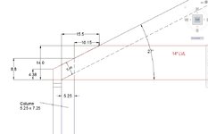
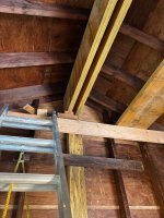
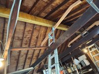
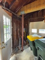
Thanks Bill. I am discussing with a structural engineer now and he also suggested going the full 24' with ridge beam. But that brings me to 16" LVLs and those suckers are almost 200 Lbs each. If I knew a local weight lifting team maybe... I was planning to leave the existing ridge board and rafters but engineer said I would have to block the rafters to the new triple ply beam (probably a 2x6 cut to match slope of roof). I'm currently thinking a 20' ridge beam from back wall of garage forward and I think 3 ply of 1.75 x 14" should suffice (at 140 Lbs ea will be more manageable for 3 guys). The single cross tie beam would be supported in middle, temporarily, until I'm ready to make the conversion to 12' single garage door in center. (The beam will be sized to eventually take the 2 columns, 12 feet apart, which I forgot to consider will block the existing separate garage doors).

I could still stick with the 16' ridge but cost-wise, I suspect it will be less expensive to do the 20'
 
To avoid these ads, REGISTER NOW!

billconner

Well-known member
Joined
Jul 20, 2021
Messages
6,964
Location
Thousand Islands NYS
My problem, but my solutions are based on what I can diy solo. (Really getting a workout site mixing and placing a footing right now.) That generally rules out LVLs. I'll struggle with the 16' 2x10 rough sawn rafters on my current project - estimated at 65-70 pounds.

I wish you all the luck and successes you need to complete this.
 
OP
M

MikeC55

Well-known member
Joined
Nov 1, 2020
Messages
420
Location
CT
Thanks Bill. Luckily, I do know a couple of strong (young) guys that can help me with the big beams. Now I'm at the point where I have to make a decision on the garage door (in order to size the header and ensure the ridge beam columns are far enough apart for the tracks. Or I could go with roll-up door which can be wider, if I want. I think I'd prefer the look of a traditional garage door but 12' wide (7' high) is not a common size. Grrrr. nothing is easy. If I use a wider OH door, then it drives the columns further apart and increases the beam size...
 

Innovate1

Well-known member
Joined
Jul 28, 2014
Messages
4,288
Location
Illinois near St. Louis, Missouri
The gable wall with the overhead door should be non load bearing, so minimal header required.
But not if it supports a ridge beam.

As far as getting the beam in place it seems like you will need to open up one of the gable ends so you can get the beam in place before cutting the joists out. You open the hole. Then lift one end of the beam up into that hole. One end is half the weight and you could set up a tripod out of some long lumber and a winch to lift it. Then secure that end in the opening. Move the tripod to the other end and lift it up. Put some scaffolding or build some rack to support the beam as it slides into the structure. Then lift one end at a time to the ridge. Would be a lot faster with help but seems doable with one person. Just need to build some temporary supports and constraints and move it a little at a time.
 

billconner

Well-known member
Joined
Jul 20, 2021
Messages
6,964
Location
Thousand Islands NYS
But not if it supports a ridge beam.

As far as getting the beam in place it seems like you will need to open up one of the gable ends so you can get the beam in place before cutting the joists out. You open the hole. Then lift one end of the beam up into that hole. One end is half the weight and you could set up a tripod out of some long lumber and a winch to lift it. Then secure that end in the opening. Move the tripod to the other end and lift it up. Put some scaffolding or build some rack to support the beam as it slides into the structure. Then lift one end at a time to the ridge. Would be a lot faster with help but seems doable with one person. Just need to build some temporary supports and constraints and move it a little at a time.
Based ridge beam not extending to gable as described, it seemed not load bearing. With posts and rafter tie beam, the ridge beam may just be cantilevered to gable, and not bearing on it.

I feel Mike has gotten input overload and I was stepping aside but then no one responded on the lvl help requests, so posted.
 

Denwood

Well-known member
Joined
Sep 22, 2014
Messages
4,186
Location
Thunder Bay, Ontario, Canada
If you leave a few truss ties (at each end) in place, and use a few ratchet straps (for safety), you will find a 20" ridge is not so bad to get in place. Lift one end at at time, assemble in place. I found a few ratchet straps at each end makes it quite easy to lift in stages. I did my roll up garage door (solo) this way. A small block chain hoist is also pretty handy if you have one. If you have one helper, it will be easier than you think! You can tack a few scabs in place between existing rafters to hold the ridge up while assembling it in place. A telepost or two with blocking will allow you to pre-load the ridge in place as you place your cross support beams.

You'll be happy you went to 20', instead of 16' like I did, the first time you lift a car :)
 

Sumboodie

Well-known member
Joined
Mar 20, 2021
Messages
10,676
Location
AK
What lift can fit in less than ~12ft?

If you want to work under a car, you'll need 10-11ft at least.
 
OP
M

MikeC55

Well-known member
Joined
Nov 1, 2020
Messages
420
Location
CT
I did get a PE to review my plans and he concurs with my choices of beams and gave me details on column footers, fastener schedules, brackets to use, etc.
I've been using a MaxJax in my current 8' garage and I know not all of the 2 post lifts on the market require 12' for the columns. Even with the MJ, having an extra 2' of head room would allow me to fully lift my son's Jeep Grand Cherokee and other SUVs. But I do plan to get a lift with more capacity.
The ridge beam will be 3 x 14" LVL and the tie beam with column support will be as shown. I was hoping to figure out a way to squeeze in an overhead garage door without impinging on the lift space but it would have been asking for trouble.
https://www.garagejournal.com/forum/threads/high-lift-garage-door-tracks.501755/
Based on my current dimensions, and assuming lift columns are 8' apart, I should have a good 12' overhead in center of the space.

It will be done in 2 phases. First will be installing the ridge beam and cross tie beam with a single column in the center to pick up the forward ridge support. This allows me to keep using it as a 2 car garage until I'm ready for phase 2, where concrete for reinforced slab will be poured (for lift attachment) and stem walls where garage doors used to be. First thing I need to do is move the window in back wall away from center (for rear ridge support). It will be a 10' wide opening in from with carriage style doors.
 

Attachments

  • Gar-6.jpg
    Gar-6.jpg
    128 KB · Views: 66
  • Gar-6s.jpg
    Gar-6s.jpg
    69.9 KB · Views: 35
  • front.jpg
    front.jpg
    93.1 KB · Views: 25
Last edited:
OP
M

MikeC55

Well-known member
Joined
Nov 1, 2020
Messages
420
Location
CT
I searched google for a PE near the zip code of the house. A few came up that seemed to offer what I was looking for. I filled out the contact form and (only one) responded to this:
"I have a 2 car garage (approx 24' x 24') with 8' ceilings and 6/12 pitch roof (rafter construction). Existing rafter ties are 2 x 8. I want to size a 16' LVL ridge beam to open up a portion of the ceiling (eliminate rafter tie beams in this area). This is to be installed under the existing ridge board (2 x 8) to which the rafters are attached. There will be LVL rafter ties to pick up point load of ridge beam supports. These will have 2 columns spaced 12' apart, centered on ridge to support LVL tie beam. I can supply AutoCad drawing. House is in Redding, CT with snow load 30 psf, dead load 20 psf."
In his response, he was a bit surprised at how specific my request was and he asked if I was going to do the drawings and if I was planning to pull a permit (yes, no). I explained I was just looking for help on the engineering side to make sure my beam selections and columns were adequate. He asked for pdf views from my drawing and we went from there. He suggested going with the full garage length ridge beam as some of you did and although I decided against that, I did go with 20' instead of 16'. He figured around 3 hours to check the beams I selected, specified columns to use, footers for the columns, fastening schedules, brackets to use, etc. It ended up costing $675, which I thought was a fair price based on a similar project on my old house when I wanted to take out a load bearing wall back in 2004. At that time, the local PE specified the LVL beam, end support details, and the beam reinforcement for basement beam to carry the point load to the foundation. This cost around $400 back then.
 
OP
M

MikeC55

Well-known member
Joined
Nov 1, 2020
Messages
420
Location
CT
I haven't started on this yet but have another question relative to roof venting. The existing roof has no eaves/soffit. It stops at the side walls, like in this photo. If I install the ridge beam to allow a 'cathedral' ceiling, is there any way I can ventilate the roof? The existing rafters are 2x6 and I was thinking I would either sister 2x10 to them or Glue and screw 2x4s edge-wise to the bottom of each 2x6 to increase it's depth. This would allow installing R-30 bats but if I want to attach the ceiling to the bottom of the rafters, I guess I'm stuck with essentially no option for ventilation of roof. The whole point of the ridge beam is to allow higher ceiling for a lift, placed in center. There is a small open area above the collar ties, so I could install small gable end vents up there. Any ideas? I guess I can just go with no ventilation knowing that isn't good for the roof (when I heat the interior while working in there; most of the time it will be unheated), and eventually, when roof needs to be re-done, I can sister in some rafter extensions for eaves... Maybe I'm worrying too much about this?
 

Attachments

  • IMG_3494 eave.jpg
    IMG_3494 eave.jpg
    58.8 KB · Views: 17
  • Roof detail.jpg
    Roof detail.jpg
    164 KB · Views: 20
OP
M

MikeC55

Well-known member
Joined
Nov 1, 2020
Messages
420
Location
CT
I'm getting closer to actually tackling this project, but am thinking of making one change. I'd like to do away with the two lally columns and re-size the beam for the full span of garage. The 20' span ridge beam has been sized for the appropriate snow load and dead load and I end up with almost 6,000 pounds load at each end. So now I'm looking for an LVL that will span 23.5' with a 'point' load of 6,000 lbs. Since the walls are only 2 x 4 construction, I'm sure I will need to add a column against each side wall for bearing down to footing and I'm not how much trimming is allowed for the roof angle. It seems that the LVL tables are set up for distributed loads only and I'm not sure if there is a way to use for this point load case. https://bmc.a.bigcontent.io/v1/static/Boise_Cascade_Versa-Lam_LVL_Eastern_Design_Guide_2020/.pdf
 

Attachments

  • Ridge beam-3.jpg
    Ridge beam-3.jpg
    125 KB · Views: 17
  • Top View.jpg
    Top View.jpg
    139.3 KB · Views: 16

billconner

Well-known member
Joined
Jul 20, 2021
Messages
6,964
Location
Thousand Islands NYS
Been so many I have trouble recalling this one but on your question, very simple engineering says a beam supporting a uniform load of X will support a concentrated load of X/2 at the center. So if you have a concentrated load of 6000 pounds at the center a beam that will support 12,000 pounds uniform load is required. But a good lumberyard ought to be able to get that engineered for you from their LVL supplier.
 
OP
M

MikeC55

Well-known member
Joined
Nov 1, 2020
Messages
420
Location
CT
Thanks, Bill. I do plan to have lumber yard double check, but I want to understand these calculations. I cracked open the old statics book and find that for a simply supported beam with point load at center, Max Moment = PL/4 and Max Deflection is P(L cubed)/48EI. Using the Versalam number for a 3 ply, 14" deep beam, I get Max Moment 35,250 ft-lbs, and Max Defl = 1.17 inch. LVL design values allow 13,965 Lbs for shear load and 43,552 ft-lb for Max Moment, so I seem to be ok there. L/240 deflection criterion comes out to 1.175 inch for the 282 inch span. Since it's only a garage roof, I'm thinking this is good, although I may add another ply to stiffen it up a bit more (and I may add a plywood floor to the forward portion where rafter ties will still be used, for some light storage). The 4th ply drops the deflection to 0.87" and I'm going to use a metal ceiling, so no worries about drywall joint cracks. The side walls on the garage are only 2 x 4, with no eave and a 6/12 roof pitch, so I think I'm going to need more bearing area because of the corner trim to clear roof. I plan to use Versa-lam columns for this (8' long), but aside from being at least 7" wide (to support full beam thickness), I'm not sure if 3.5 depth is enough when factoring in the trim angle on upper corner.
 
OP
M

MikeC55

Well-known member
Joined
Nov 1, 2020
Messages
420
Location
CT
It's to get more height for the lift. I have to put it in the middle.
 
To avoid these ads, REGISTER NOW!
OP
M

MikeC55

Well-known member
Joined
Nov 1, 2020
Messages
420
Location
CT
Here's close up of the beam where end sits on top plate. I suspect I'll need more bearing area than what the 5.25" column shown gives. I found this chart, but it applies to BCI joists. Does anyone know of something similar for LVLs?
 

Attachments

  • Corner trim.jpg
    Corner trim.jpg
    59.3 KB · Views: 13
  • Beam Ends.jpg
    Beam Ends.jpg
    399.4 KB · Views: 14
OP
M

MikeC55

Well-known member
Joined
Nov 1, 2020
Messages
420
Location
CT
I didn't think the beam tables were accounting for any beveled corner at the support ends. I realize the ends have little or no bending moment, but I would think if the end is beveled, such as in my example, the shear load is being resisted by a lot less than full beam depth. With the 6/12 pitch (27 deg), around 2/3 of the beam depth is trimmed away where it rests on the wall. I found this in a brochure for HySpan LVLs.
 

Attachments

  • Chamfer.jpg
    Chamfer.jpg
    26.8 KB · Views: 13
Last edited:
OP
M

MikeC55

Well-known member
Joined
Nov 1, 2020
Messages
420
Location
CT
This is what I was looking for. If I understand it correctly, I think it's telling me I can't use the existing 3.5" bearing (the 2 x 4 wall top plate) as-is because it doesn't meet the 'de' spec of 0.6 x beam height. By adding the 5.25 column, I do get to that minimum de, 8.5 (see post #141), and with a 4 ply beam, I have plenty of extra for reaction force (2826 lb x 4 = 11,304 lb). Any flaws in my logic?
 

Attachments

  • LVL_Tapered_End-2.pdf
    100.4 KB · Views: 3

firebirdparts

Well-known member
Joined
Jun 8, 2016
Messages
10,609
Location
Kingsport, TN
It's probably fine. Ideally, you'd like to have that point load go down to the foundation, and for the foundation to be designed for it. The former consideration depends on the location of a new post. none of this is going to exist wholly inside a 3-1/2 wide wall of course. I'm not sure what's under your framing.

Replacing your existing corner with something suitably enormous would be ideal here, but that's the hardest way. Not truly hard. Maybe I should say "least easy".

I know you're planning on putting a footing under it, but as you moved the column to the corner of the building, the area under the building is becoming unavailable. When it was in part of the gable end wall you could just dig all you want.
 
Last edited:
OP
M

MikeC55

Well-known member
Joined
Nov 1, 2020
Messages
420
Location
CT
It's not quite in the corner, 4 feet back from front corner of garage. But your comment did get me thinking about the the situation next to the exterior wall. The 2 x 4 wall sits on a concrete block foundation and the block extends beyond the 2 x 4 bottom plate by around 3 inches. I had wanted to attach the column to the exterior wall for lateral stability but if I do that, I'm not sure what to do at column base due to the block sticking out beyond the wall. I suppose I could notch the column to fit (not a good idea I'm guessing), I could carefully cut into the block wall so the column would sit fully at floor level, and then pour a small footing inside the wall for the portion that doesn't sit on the block. Or I can move the column further inboard so it sits next to the wall with a full footer beneath it (see diagrams). The original design with lally columns, the PE spec'd a 24" 24" x 12" deep footing (he said I didn't need to go to frost depth because it was inside the garage). I feel better extending it down to 2' but am not sure about the column not being in the center of this footing. For the latter case, I would still fill in the gap between inside of wall and column face with solid lumber in order to still use exterior wall for lateral stability.
 

Attachments

  • Garage floor-2.jpg
    Garage floor-2.jpg
    33.9 KB · Views: 14
  • Garage floor-1.jpg
    Garage floor-1.jpg
    30.5 KB · Views: 11

C-S-H

Well-known member
Joined
Jan 18, 2024
Messages
145
Thanks, Bill. I do plan to have lumber yard double check, but I want to understand these calculations. I cracked open the old statics book and find that for a simply supported beam with point load at center, Max Moment = PL/4 and Max Deflection is P(L cubed)/48EI. Using the Versalam number for a 3 ply, 14" deep beam, I get Max Moment 35,250 ft-lbs, and Max Defl = 1.17 inch. LVL design values allow 13,965 Lbs for shear load and 43,552 ft-lb for Max Moment, so I seem to be ok there. L/240 deflection criterion comes out to 1.175 inch for the 282 inch span. Since it's only a garage roof, I'm thinking this is good, although I may add another ply to stiffen it up a bit more (and I may add a plywood floor to the forward portion where rafter ties will still be used, for some light storage). The 4th ply drops the deflection to 0.87" and I'm going to use a metal ceiling, so no worries about drywall joint cracks. The side walls on the garage are only 2 x 4, with no eave and a 6/12 roof pitch, so I think I'm going to need more bearing area because of the corner trim to clear roof. I plan to use Versa-lam columns for this (8' long), but aside from being at least 7" wide (to support full beam thickness), I'm not sure if 3.5 depth is enough when factoring in the trim angle on upper corner.
You need to understand the structural implications of changing your structural system. The roof load will try to make its way to the walls using the stiffest load path. You are proposing to support 12000# of roof load using LVL's that will deflect about 2" total at the center of the roof ridge. This would push the walls out about 1" each. But more importantly it will try to deflect the roof shear plates (plywood) that same amount. The roof shear plates, which are very stiff, will act as deep beams and try to take most of the load to the remaining rafters/ties and the gable end walls (also very stiff). At your 6:12 roof pitch there is a lateral thrust of 24000# that will try to rip the plywood off of the rafters in shear, after which your LVL system will finally start taking the load. So your deflection is about an order of magnitude too high.

You were on the right track at the beginning of this thread. Sister the rafters such that the rafter tails work in flexure and shear, and move the rafter ties up. You will need 2 or more rafter ties per sistered rafter set to get the nail pattern right. Match the flexural stiffness of the remaining original rafters/ties by calculating deflections. Then the load will be distributed along the eave walls, and there will be no heavy lifting for you. Your engineer will love to run these easy calculations for you.
 
OP
M

MikeC55

Well-known member
Joined
Nov 1, 2020
Messages
420
Location
CT
I'm not sure I follow you CSH. I did have a PE who does a lot of residential work review my plans and he agreed the 3-ply 14" 20' long LVL would work (https://www.garagejournal.com/forum...-ceiling-questions.500414/page-4#post-9707464). I know there will be some deflection, but 2" seems excessive (I will check). The existing roof only has a ridge board and 2 x 6, 16" OC rafters, yet there is no obvious deflection in the center (2 x 10 rafter ties, 48" OC). I'm planning to remove 4 of those rafter ties via the LVL ridge beam. My understanding is that the whole point of an appropriately sized ridge beam is to take the spreading forces off the side walls. The original plan was to uses a PSL column to take the rear gable wall load to the foundation, while the forward support was going to have 2 columns 12' apart to support the cross tie beam with the 6,000 Lb point load from forward end of ridge beam. The change I want to make is instead of these intermediate columns, I want to size the cross tie beam (~23.5' length) such that it has no intermediate columns. My calculations (https://www.garagejournal.com/forum...ceiling-questions.500414/page-4#post-11105806), which have yet to be checked by my PE, say my 4-Ply 14" LVL will deflect a bit under 1".

On the 2nd part of your post, I definitely don't follow how stiffening the remaining rafter ties will get my my 20' of open space (a car lift will be installed in center). When you say 'move the rafter ties up', how high up? Raising them 1/3 the gable height gets me maybe 24". The LVL will open it up quite a bit more.
 

C-S-H

Well-known member
Joined
Jan 18, 2024
Messages
145
The calculated 2" deflection is the sum from ridge beam with 12000# dist load plus 6000# point load on each 24' LVL. That is alot. The original rafter/rafter tie system is 6' deep, and is therefore very stiff. It is understrength by modern wood standards and design with ties at 48". If sistering rafters and moving rafter ties up can't give you adequate clearance (engineering design will tell you the answer to this), then I would remove the lower 4 ft of roof deck sheathing on one side and slide some scissor trusses into position.

I think it is important to keep the roof load distributed along the eave walls. Your plan tries to concentrate loads, and creates competing load paths of radically different stiffnesses.
 

C-S-H

Well-known member
Joined
Jan 18, 2024
Messages
145
I do kind of like the scissor truss mod this guy does to his garage.
It appears that original trusses are 2 x 4 and I'm not quite sure what he is doing with the new 2 x 4 he adds to the rafter area but it would seem you could do this same sort of modification to rafter construction where you would add each piece for the scissor on opposite sides of each rafter and then have the vertical tie sandwiched in the gap between the scissor boards. 2 x 4s could be plywood gusseted in if needed. It would be nice not having to worry about lifting / maneuvering any real heavy beams.
30 seconds on a hand calculator will show you that this system is terribly structurally deficient.
 

BurtEggley

Well-known member
Joined
Oct 8, 2024
Messages
864
Mike - you started this almost 3 years ago. The cost of increase in materials is more than it would have cost to hire the PE just to do the drawings, pull permits and do it. If you keep making changes, you will never get it done until you are too old to use it. Trust me, the plans I put off to do things 7 or 8 years ago have passed me by already. Just hire the PE, do the drawings and dive in. Then get a chance to use it.
 
OP
M

MikeC55

Well-known member
Joined
Nov 1, 2020
Messages
420
Location
CT
i hear ya, Burt. I am officially retired now, so no excuses. I do have a PE checking my latest change. I am definitely going to get thing going this summer.
 
OP
M

MikeC55

Well-known member
Joined
Nov 1, 2020
Messages
420
Location
CT
Well, I'm finally getting this project going (had to keep the wife happy by remodeling the kitchen first). I have the LVLs, columns, brackets, etc. My PE agreed with my beam/column choices and I'm getting ready to lift the spanwise LVLs into place for the 4 ply beam. These are just shy of 24', 14" depth and weigh in at around 168 lbs each. My plan is to install a (forged) 1/2" screw eye into the ridge board at the location where these LVLs must be raised to have their ends sit on top of the side walls. I will hang a half ton chain hoist on a 5' chain on the eye and wrap a rigging strap around the LVL to lift it in the center. I don't think the 200 lb point load on the (2 x 10) ridge board should be an issue if I lift slow and carefully.
 

Attachments

  • Top view.jpg
    Top view.jpg
    65.1 KB · Views: 14
  • Sect B-B.jpg
    Sect B-B.jpg
    82.6 KB · Views: 27
OP
M

MikeC55

Well-known member
Joined
Nov 1, 2020
Messages
420
Location
CT
I ran into a little problem I hadn't considered while moving one my existing rafter ties. Because the rafters are 16" OC, I can't skew the rafter tie enough (diagonally) to slip it off the wall top plate. I was hoping to re-ruse it and so don't want to cut it. Even laying it flat-wise, I can't bend it enough to clear the top plate. This means I'll have to do some 'surgery' in order to get the LVLs in position. The only options I can think of are cutting a slot in the top plate to allow one end of LVL to pass through from underneath, or cut and remove a section of rafter to allow more diagonal length to angle it in there. After the LVLs are in place, I would glue/screw a splice in the top plate or rafter. I suppose I could also remove a small portion of roofing to allow sliding in the LVL from the side, but I'd really like to avoid disturbing the roof shingles. Any other ideas?
 
Last edited:
OP
M

MikeC55

Well-known member
Joined
Nov 1, 2020
Messages
420
Location
CT
Crickets? If I cut the (double) top plate, should I expect the wall to immediately bow outward or would that happen over a longer time span? I do have a cable/come along I can attach to one side of the cut to prevent spreading. Or would angle braces to the ground on outside (from top of wall) do the job?
 
OP
M

MikeC55

Well-known member
Joined
Nov 1, 2020
Messages
420
Location
CT
In case anyone is interested, I did cut a slot in the top plate. To avoid creating a hinge in the wall, I double strapped the top plate on outside of garage. It seems to be fine. I do have a cable tensioned between left/right side to avoid wall bowing. I was also successful in using the chain hoist attached to ridge board to lift one beam into place. No creaks or groans from stucture.
 

Attachments

  • IMG_0430.jpeg
    IMG_0430.jpeg
    765.2 KB · Views: 18
  • IMG_0432.jpeg
    IMG_0432.jpeg
    1.1 MB · Views: 17
  • IMG_0433.jpeg
    IMG_0433.jpeg
    1.2 MB · Views: 22
OP
M

MikeC55

Well-known member
Joined
Nov 1, 2020
Messages
420
Location
CT
I have the 24' beam in place. Getting the ridge beam up top was a bit trickier, since the chain hoist limits the lift to about 16" below the ridge board. I installed collar ties at about the same height on the rafters near each end (near backwall gable and rafter pair just short of beam length). With the 20' beam lying flatwise, I picked it up with the chain hoist (lift point centered on beam) to about 1' above the existing rafter ties, I then tilted the beam end near backwall down causing the other end to go up) and slid the other end over the far collar tie. Then with block & tackle, raised the backwall end of beam to the backwall collar tie height (and with a helper) maneuvered it over the collar tie. Then did this for other 2 plys, so all 3 LVLs are in temporary position near the final destination. I then took one of these, and rotated it 90 degrees, (so beam depth is vertical instead of flatwise). Then (via ladder at each end), lifted each end on my shoulder and placed blocking between beam and collar tie to gradually raise each end until it could be slipped onto the PSL support columns (which were braced into place). Whew! I have the first one centered on the support columns.
 

Attachments

  • IMG_0526.jpeg
    IMG_0526.jpeg
    600.1 KB · Views: 19
  • IMG_0532.jpeg
    IMG_0532.jpeg
    635.6 KB · Views: 22
Last edited:
OP
M

MikeC55

Well-known member
Joined
Nov 1, 2020
Messages
420
Location
CT
Beams and lally columns installed. Adding collar ties now.
 

Attachments

  • IMG_0551.jpeg
    IMG_0551.jpeg
    756 KB · Views: 10
  • IMG_0554.jpeg
    IMG_0554.jpeg
    1.2 MB · Views: 10
  • IMG_0559.jpeg
    IMG_0559.jpeg
    526.3 KB · Views: 10
To avoid these ads, REGISTER NOW!
Top Bottom