To avoid these ads, REGISTER NOW!

rattle_snake's random shop projects v0.1

To avoid these ads, REGISTER NOW!
OP
R

rattle_snake

Well-known member
Joined
Jun 25, 2015
Messages
5,315
Location
Chandler, AZ
Is there a plan for a similarly tapered plate at the rear? The boxed to not boxed transition needs to be gentle or you risk cracks where the torsional stiffness changes dramatically.
Yes, doing the boxing in stages and will terminate with a tapered end. Where exactly not sure. Currently back to the body mounts. Might go one more section then cab would need to come off.
Looking good Justin. I like the sleeves and boxed frame.
Thanks. Enjoying this phase of the build.
 
OP
R

rattle_snake

Well-known member
Joined
Jun 25, 2015
Messages
5,315
Location
Chandler, AZ
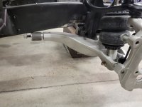
With the IFS up an inch and forward 2, the LCA rear mount almost fits. The factory mount has an oversized oval hole.
XyKDQ9-X6vrk2U_icVCA=w1214-h911-s-no-gm?authuser=1.jpg

With LCA forward bushing centered and torqued the clearance is not much. A piece of 9/16 DOM could be used instead and not need frame modifications. But adjustability is limited without a bushing.
r5qqk9bB5SE0lqbPuIIg=w1214-h911-s-no-gm?authuser=1.jpg

In between solution is a 'standard' 2-5/8 x 9/16 poly bushing. 2" OD DOM 0.25 wall. It contacts the frame slightly.
5mzp-xozOFTOkxlqtTnQ=w1214-h911-s-no-gm?authuser=1.jpg

To fit properly I notched the frame in a similar fashion as the others. Cut out a 0.5 x 3.5 triangle and bend the lower flange up, radius intact.
8zCNmEW0Z_s3TDYPHw-Q=w1214-h911-s-no-gm?authuser=1.jpg

Now the bushing has some clearance.
0gJGyv2ylSMMfhKmmppQ=w1214-h911-s-no-gm?authuser=1.jpg

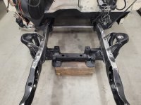
With LCA mod done, continued the frame boxing back to the cab mounts. Needs at least one more section to tie into the cross member.
wm0bmpFgRggwH2a9RS-A=w1214-h911-s-no-gm?authuser=1.jpg

Cut some brackets for the shock tower bracing. Instead of 1/4 or 3/8 material, using all 3/16 with overlays as needed. Minimal weight added.
6budu4mO9yu1kAk5R1CQ=w1214-h911-s-no-gm?authuser=1.jpg

Used 2 layers of 3/16 for the ear, then split to support in 2 planes.
t4QSjRg2NvpyriK0C2nA=w1214-h911-s-no-gm?authuser=1.jpg

Added outer braces and weld washers for the subframe bolts.
M-HPsLPYXf0zDCMGP9dg=w1214-h911-s-no-gm?authuser=1.jpg
 
OP
R

rattle_snake

Well-known member
Joined
Jun 25, 2015
Messages
5,315
Location
Chandler, AZ
Coming along nicely. That's going to be stout.
Thanks. That's the idea, solid and rigid. Kinda the opposite of most CV IFS installs. Not that quick and easy is bad, just not my style.

Looking good Justin.
Thanks Mike!
Has been a lot of grinding and welding and grinding. Really like the 2nd paddle style cordless angle grinder I recently bought. One with a death wheel and the other with flap wheel. Usually use 60 grit, bought some 40s they plow through weld but wear quick. But for the money it's well worth the time saved. The older trigger style grinder has a wire brush, and now that it is cordless I actually use it. I have four larger capacity batteries and they are more than enough for how I use the tools.

The modifications to my mechanic stool really make it work a lot better. Wider base and bigger wheels make all the difference. Working low to the ground is hard on my back and the improved stool makes a difference. Needs a larger seat, I have been wanting to make a new seat pan/pad and cover with some nicer material, in Viper tan.
 
OP
R

rattle_snake

Well-known member
Joined
Jun 25, 2015
Messages
5,315
Location
Chandler, AZ
Fired up the plasma and cut the parts for the second side. Hopefully the last batch on the table for this machine.
0_HjZd9-GJv5S1Z3zXhw=w1214-h911-s-no-gm?authuser=1.jpg

Hoping the cleanup effort on thick material with a larger capacity machine is significantly reduced.
CpKmGNhKMOGB6E_cHhAQ=w1214-h911-s-no-gm?authuser=1.jpg

Welded up the frame boxing plates and slicked out the frame rails. Tacked the upper supports in place.
E44SBeASf0ierk_PcLZg=w1214-h911-s-no-gm?authuser=1.jpg

One step closer to getting it back on it's wheels. Frame boxing needs to go one more panel back, with tapered ends. Rear LCA mounts, steering, brakes.
bESjac8k5Yow8y6HuGug=w1214-h911-s-no-gm?authuser=1.jpg

With the frame welding done I removed the brace between the towers. No preload so nothing moved. Measured the frame horns to see what the heat did. Narrow by over an inch, well that *****. Looked more closely at the frame rails and decided that they are both bent to the right. I corrected the right rail somewhat. Took some cross measurements and the left side needs to move out and right is all right. Plan to cut the flanges and box plate where the seams are and reposition as needed. This way the core support and bumper will fit properly.
 
OP
R

rattle_snake

Well-known member
Joined
Jun 25, 2015
Messages
5,315
Location
Chandler, AZ
Nice work and those welds.....
Thanks.
'those welds', is that a good thing or ?

I'm always critical of my welds. I've improved a lot over the years and confident in the results, but not consistent enough to look good.. A lot of welds get covered or slicked out.
you are making it look easy and we know it is definitely not.
Thank you. I've had some time to think about it. It's not the first one so I already know how to screw it up. The frame being bent doesn't help. Welding itself warps things. Have to just take it one step at a time, adapt as needed.
Am I the only one who is blown away by how clean Justin's workspace is?
I can't work in chaos. The bed of the truck is chaos, filled with all the parts and pieces. But that is not the workspace.
I blow the grinding dust back under the truck. I swept up pounds of it last night.
 
To avoid these ads, REGISTER NOW!
OP
R

rattle_snake

Well-known member
Joined
Jun 25, 2015
Messages
5,315
Location
Chandler, AZ
Got the new machine setup and cutting on the table.
Difference in cut quality and clean-up is very significant on thicker material, as expected.
IEDP3rEnw8fPcRfJ0QPQw=w683-h911-s-no-gm?authuser=1.jpg

The ground clamp is ****, so I cut it off and tossed it in the trash. Shortened the lead somewhat, crimped a lug on it to work with a mag setup. Didn't work for **** so I took it apart and ended up adding a washer to make spring force higher and hold the electrode vertical to contact better.
Cut 15' off the CNC cord.
The Langmuir THC is intended to use an external 'signal conditioner' as a filter/protection and/or a 50:1 divider. The THC input on the controller is only for raw voltage, probably could skip the box, but just used it for now. Plasma has both raw and 50:1 outputs, plus series Rs that could be used as protection.
C4Ss1ZehxUlnMHarsNcw=w1214-h911-s-no-gm?authuser=1.jpg

The unit has an external reg/filter setup. My experience with these type of filters is that they pass water vapor. I swapped over the Motorgaurd filter I had on the other machine.
uMWm9eM0kYqBtjvypZOSQ=w683-h911-s-no-gm?authuser=1.jpg
 
OP
R

rattle_snake

Well-known member
Joined
Jun 25, 2015
Messages
5,315
Location
Chandler, AZ
Looking good on the IFS on the truck. Are you planning to make motor mounts off of the CV mounts or fab your own?
Thanks. Going to fab something, need to get the engine back in and see how things line up and make a plan. In general, I believe the motor mount pillars on the CV k member are too far forward. I see that some of the mounts sold attach to the rear of the pillars. I moved the IFS forward 2" so I assume it will just make the situation worse. It is possible to not use the pillars at all, or use them in conjunction with the frame to further tie things together.
Beautiful! and the clean shop. OMG
well thanks then. Some of the work is laying on the ground so I like to keep the space clean.

My daughter's ex boyfriend did welding school. They had to wear ear plugs at all times. I asked why. So a molten ball doesn't enter your ear and burn a hole through it.

So last night while I was welding on the bottom of the frame I put a towel over the side of my head. I still got a piece into my ear but it was small and not so hot by then.

I like the drums in the garage.
Me too. Fun to play the drums. They get dirty, but they get used.
I have a friend who is a drummer in a death metal band for a long time. He puts on small events at his home shop, the 'Metal Box' (it's a metal shop). Dude has Slayer level speed and precision. It's pretty amazing to watch. All the bands I have seen there are pretty decent. Only a few miles from my home. Complete with mosh pit.

Went and saw the band 'The Sword' last week. Was a great show. I'd call it stoner metal. Riffs, riffs and great interleaved guitar work.
 
OP
R

rattle_snake

Well-known member
Joined
Jun 25, 2015
Messages
5,315
Location
Chandler, AZ
Tackled the bent frame horn issue. Step one was cut three sides of the frame at the box seam and bend it out. That left a decent gap, right about 3/16. Then how to weld it back up without contracting back to the wrong place.
To make the repair more robust, I used a thin strip of 3/16 to shim the gap. This holds position and provides a backing to the weld puddle. I set it in as far as possible to still have it hold the gap open. Weld all three together, up, hot.
uymF1e8dmTLo1r-LN_fCA=w683-h911-s-no-gm?authuser=1.jpg

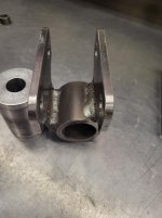
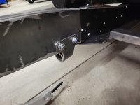
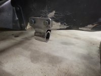
Then on to the LCA rear mounts. Simple task, but not simple to do well. Have to build in place with the compound angles. Started with the outer plate, clamp in position, drill one hole. Pin, drill the other. Tack the plate to sleeve. Center punch the inner flange, drill more holes. Bend the inner plate in the press to fit, tack. Then finish weld on the bench with clamps the spacers to hold the shape.
7ELKDf7X4K8cST7d6-SA=w1214-h911-s-no-gm?authuser=1.jpg

hlwMNgctsYf7ZWhuzk0uA=w683-h911-s-no-gm?authuser=1.jpg

Welder all the way up. Need a bigger welder....
ysRA8Lz9SwqYVoDsKV3Zg=w683-h911-s-no-gm?authuser=1.jpg

Will see if headers interfere with the bracket and nuts....
vOiyJuIxCPKnhl3lqmSg=w1214-h911-s-no-gm?authuser=1.jpg

Not the final HW.
Ei98tcPVZp9HyM8YOgcw=w1214-h911-s-no-gm?authuser=1.jpg

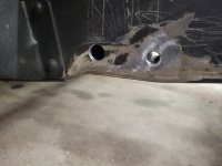
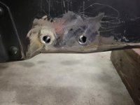
With the bolts close to the lower flange, sleeves aren't really needed. I put them in anyway. Might have been able to get them into the frame gap from the box end, weld the closer one, but the forward would be difficult to secure. Instead drill one side (outside) and top weld the sleeve. 0.5 x 0.75 DOM.
sVm3M4wU8MrxK-syNufQ=w1214-h911-s-no-gm?authuser=1.jpg

Sleeveage and notchage.
bhcJdcpZUf8L7KnmP_uQ=w1214-h911-s-no-gm?authuser=1.jpg
 

zmotorsports

ALLIANCE MEMBER
Joined
Oct 20, 2009
Messages
21,604
Location
Northern Utah
Nicely done Justin.

I have also used the "plate filler" trick to fill gaps larger than I felt comfortable with just wire before with excellent results. Works as intended to fill the gap and control pull back.
 

Ohmthis

Well-known member
Joined
Jan 20, 2013
Messages
3,031
Location
Outside of Louisville KY
“Thanks. Going to fab something, need to get the engine back in and see how things line up and make a plan. In general, I believe the motor mount pillars on the CV k member are too far forward. I see that some of the mounts sold attach to the rear of the pillars. I moved the IFS forward 2" so I assume it will just make the situation worse. It is possible to not use the pillars at all, or use them in conjunction with the frame to further tie things together.”

On my F100 CV swap, I did use the pillars and offset my mounts to move the engine back. I am going to go back and do some more bracing on the backside. My biggest reason for using the pillars, it’s gives complete freedom on the inside of the frame rails. I have used the inside of the rails to run fuel lines and the main power cables (moved the battery out of the engine bay). You’re a very smart man, you’ll figure out what will work best overall for your project.
 
OP
R

rattle_snake

Well-known member
Joined
Jun 25, 2015
Messages
5,315
Location
Chandler, AZ
I didn't realize these guys were still a thing. They were just getting started when I got out of college.
Looks like they started in '03. Somehow that is now 23 years ago.
Nicely done Justin.

I have also used the "plate filler" trick to fill gaps larger than I felt comfortable with just wire before with excellent results. Works as intended to fill the gap and control pull back.
I though of doing it that way similar to doing a **** splice on tubing where you use a cross sectional shape piece, but just one side of the rectangle.

With steel prices what they are, and being 'cheap', I try to keep all the little odd shaped bits from the plasma table. In this case I kept a strip just the right size for the job.
However, when cleaning up the dross on 'scrap' I finally managed to stick my hand into the belt sander, with a fresh 36 grit. Thumb is missing part of the nail, and some skin. Shoulda just tossed the piece...
On my F100 CV swap, I did use the pillars and offset my mounts to move the engine back. I am going to go back and do some more bracing on the backside. My biggest reason for using the pillars, it’s gives complete freedom on the inside of the frame rails. I have used the inside of the rails to run fuel lines and the main power cables (moved the battery out of the engine bay). You’re a very smart man, you’ll figure out what will work best overall for your project.
With frame boxing I kinda prevented myself from running stuff in there. The sleeves block the channel pretty good. Not sure an -6AN nut will fit. #2 wire should though. Might cut some access holes if it makes sense.
Using the pillars instead of frame mounted mounts leaves a lot more room for headers, including getting them in and out.
 
To avoid these ads, REGISTER NOW!
Top Bottom