
You are using an out of date browser. It may not display this or other websites correctly.
You should upgrade or use an alternative browser.
You should upgrade or use an alternative browser.
Show us your VFD conversions/installations
- Thread starter Techie1961
- Start date
Oh of course, forgot it goes through the transmission haha...the invertek VFDs will do slip conpensation if you give them motor nameplate data (inc RPM), and display it on the front panel. that does NOT account for any gearboxes (i.e. shows you motor RPM).
Then using the marine RPM gauge and setting up the sensor somewhere at the back of the spindle would be a lot more feasible.
I dug this WEG soft motor starter out again, I'm guessing I should remove the vfd and have it tested by my previous employer.
The problem with the VFD showing the RPM is most machines have a transmission of some sort between the motor and spindle. That is where a cheap digital tachometer comes in handy. Amazon has many of them.Hey I have a 3kw lathe and am considering mounting a VFD on it. I have a couple questions:
What VFD would I need that would be capable of showing the RPM? I don't mind if I have to measure the RPM and the enter the max value or sth like that, but I would really need that function.
A very neat thing would be if it is possible to have the VFD output the RPM to such a gauge. Says it works on 24V DC too, so it'd be great.
Alternatively I'd mount the sensor and some magnet on the spindle at the rear...
I'd also want an external potentiometer to adjust the speed, but I assume all allow for that.
I thought about putting one on my PM1200, but I can eye ball the RPM close enough. Also my PM1200 has a speed chart, so if I set the VFD for 60 hertz I can look at the speed chart, but I rarely worry about it.
laser3kw
Well-known member
I experimented with a 12vdc digital automotive tachometer powered from a 12vdc wall wart to do that. I proved the concept and shelved it to do later. On my lathe, there is a part on the back side of the spindle with two screws in it. I replace the set screws with socket head screws and then used an inductive proximity sensor (12vdc also) to sense when each screw head passes beneath it. Two pulse per rev would equal a "4cylinder" automotive engine. The good thing is, the screws do not have to be evenly spaced, just so long as there are only two. This set up will read the true spindle speed regardless of belt ratio or gear ratio selectionA very neat thing would be if it is possible to have the VFD output the RPM to such a gauge. Says it works on 24V DC too, so it'd be great.
Alternatively I'd mount the sensor and some magnet on the spindle at the rear...
jmarkwolf
Well-known member
Didn't this thread used to be a sticky?
laser3kw
Well-known member
yup - got non-stickied due to slow moving
Sure was easy to find though!yup - got non-stickied due to slow moving
got another one for y'all:
Supersplit, with a 1.5HP 3ø motor + 110v 1ø input VFD. 1.5hp line start farm duty motor is hard to start on a shared circuit or suitcase generator. This'll run on a battery inverter or suitcase inverter generator. 10s acceleration time.
had some teething issues with the internal cooling fan blades hitting the back of the speed pot mount and shutting it down, flipping it around buys enough clearance to delete that problem.
454ragtop
Well-known member
^ What VFD is that? I haven't seen any 115V input VFD's bigger than 1 HP. Do you use the variable speed with that?
Invertek ODE-3-210058-104B^ What VFD is that? I haven't seen any 115V input VFD's bigger than 1 HP. Do you use the variable speed with that?
output: 1.1 kW (1.5 HP), 5.8 A 3ø,
input: 110-115 V, 1ø
IP66 Outdoor Switched Variable Frequency Drive
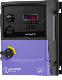
ODE-3-210058-104B - Optidrive E3 VFD Datasheet
1.1 kW (1.5 HP), 5.8 A, 110-115 V, 1-3PH IP66 Outdoor Switched Variable Frequency Drive
 www.invertekdrives.com
it's the biggest 115v VFD I can find.
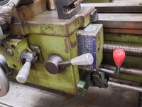
it's running at 60Hz, but with a 10 second acceleration ramp (vs DOL with the single phase motor). but it's set up like you would an engine. local controls give you run/stop (reverse disabled) with the 3 position toggle instead of using the membrane switches, and the knob is the "throttle".
Last edited:
1943 Wade 8a (Serial #407) Second Operation Lathe. Teco L510 single phase 220 to 3 phase 220 powering a 2hp motor. Vintage controls + tons of learning how to properly configure the VFD = Vintage look and feel with contemporary results. Most importantly, it makes chips. ")
When I got it, circa May 2019.

Basically how it sits today.

Teco L510 doing its thing. Top button, speed up. Middle button, slow down. Bottom button will be E-Stop. Still have to figure that one out.
When I got it, circa May 2019.
Basically how it sits today.
Teco L510 doing its thing. Top button, speed up. Middle button, slow down. Bottom button will be E-Stop. Still have to figure that one out.
Strouty
Well-known member
My new to me rotary phase converter will run 40 HP, but only 15 HP max per motor, any combination up to 40 HP total. So you could run two 15s and a 10, four 10s, or any other odd multiple like that. I have a 25 HP blower and was wondering if I could couple a VFD with that to ramp the 25 HP up so that I can use my rotary phase converter, any ideas on that? I am assuming I would need a 25 HP VFD, then I could input my 3 phase power to it directly, not sure what would be best. The easy route would be to just install a 15 HP motor (the blower came with that as an option), but that wouldn't be any fun, right? The blower is not like a hydraulic pump or air compressor, I can easily spin everything by hand, so it wouldn't be an instant load when the motor starts.
My understanding is that you have uneven voltages from rotaries, and most 3ø VFDs are pretty stringent on acceptable input.My new to me rotary phase converter will run 40 HP, but only 15 HP max per motor, any combination up to 40 HP total. So you could run two 15s and a 10, four 10s, or any other odd multiple like that. I have a 25 HP blower and was wondering if I could couple a VFD with that to ramp the 25 HP up so that I can use my rotary phase converter, any ideas on that? I am assuming I would need a 25 HP VFD, then I could input my 3 phase power to it directly, not sure what would be best. The easy route would be to just install a 15 HP motor (the blower came with that as an option), but that wouldn't be any fun, right? The blower is not like a hydraulic pump or air compressor, I can easily spin everything by hand, so it wouldn't be an instant load when the motor starts.
for example, from the Hitachi manual
CAUTION: EFFECTS OF POWER DISTRIBUTION SYSTEMS ON INVERTERS In the cases below involving a general-purpose inverter, a large peak current can flow on the power supply side, sometimes destroying the converter module:
Where these conditions exist or when the connected equipment must be highly reliable, you MUST install an input-side AC reactor of 3% (at a voltage drop at rated current) with respect to the supply voltage on the power supply side. Also, where the effects of an indirect lightning strike are possible, install a lightning conductor.
- The unbalance factor of the power supply is 3% or higher.
- The power supply capacity is at least 10 times greater than the inverter capacity (or the
power supply capacity is 500 kVA or more).- Abrupt power supply changes are expected, due to conditions such as:
- Several inverters are interconnected with a short bus.
- A thyristor converter and an inverter are interconnected with a short bus.
- An installed phase advance capacitor opens and closes.
3% is pretty tight. if you don't want to run the blower at different speeds, maybe a soft starter or Y-∆ will get you what you want?
Strouty
Well-known member
I was only thinking for soft starting, but the variable speed wouldn't be the worst idea either.
454ragtop
Well-known member
I don't think that would work. Your blower motor is pretty much seeing a full load as soon as you turn it on, as I assume it needs 25 HP to move that much air, so as soon as the motor comes up to speed, it's fully loaded. I'd try the 15 HP and see if that does what you need it to do..My new to me rotary phase converter will run 40 HP, but only 15 HP max per motor, any combination up to 40 HP total. So you could run two 15s and a 10, four 10s, or any other odd multiple like that. I have a 25 HP blower and was wondering if I could couple a VFD with that to ramp the 25 HP up so that I can use my rotary phase converter, any ideas on that? I am assuming I would need a 25 HP VFD, then I could input my 3 phase power to it directly, not sure what would be best. The easy route would be to just install a 15 HP motor (the blower came with that as an option), but that wouldn't be any fun, right? The blower is not like a hydraulic pump or air compressor, I can easily spin everything by hand, so it wouldn't be an instant load when the motor starts.
You could try part winding starting. Would only need a contactor a cheap timer and 3 extra wires to the motor.My new to me rotary phase converter will run 40 HP, but only 15 HP max per motor, any combination up to 40 HP total. So you could run two 15s and a 10, four 10s, or any other odd multiple like that. I have a 25 HP blower and was wondering if I could couple a VFD with that to ramp the 25 HP up so that I can use my rotary phase converter, any ideas on that? I am assuming I would need a 25 HP VFD, then I could input my 3 phase power to it directly, not sure what would be best. The easy route would be to just install a 15 HP motor (the blower came with that as an option), but that wouldn't be any fun, right? The blower is not like a hydraulic pump or air compressor, I can easily spin everything by hand, so it wouldn't be an instant load when the motor starts.
Any dual voltage motor connected for low voltage can be used with a part winding starter. A 25hp motor probably doesn't have enough leads brought out to do wye-delta
Last edited:
timgunn1962
Well-known member
What is the blower?
A fan follows the "fan laws": flow varies in direct proportion to the speed, pressure varies as the square of the speed and power varies as the cube of the speed. Fans are "quadratic torque" loads and many VFDs are rated for a certain size of motor for "constant torque" (which covers most normal applications) or the next motor size up for quadratic torque.
I'd expect a rotary phase converter to have some degree of phase imbalance, but if it is small enough not to worry the VFD, it shouldn't be a problem.
The starting current for 3-phase motors on fixed-frequency supplies is usually around 6 or 7 times the rated current during Direct-On-Line starting (Across-The-Line in US terminology?) and about 2 1/2 to 3 times times the rated current during Star/Delta starting (Wye/Delta?) and this is almost certainly the reason for the maximum motor size spec. If you run a slow enough ramp-up with a VFD, you can usually keep the starting current down to no more than the rated current in most applications. I'd expect this to let you run a fan or centrifugal blower on your phase converter with a VFD.
If it's a Positive Displacement blower, then it's likely to be a constant-torque application. It might still work, but it's less certain.
I think the concerns are overblown, but the loading for the rectifier section is based on even current. you run into the same problem as single-phasing a 3ø rectifier if the currents are imbalanced, needing larger capacities on the higher voltage phases happens quickly.I was only thinking for soft starting, but the variable speed wouldn't be the worst idea either.
you've got the RLA startup, but the torque to drive the load isn't there on a centrifugal fan. the inertia of the fan blades is probably significant on a 25hp fan though.I don't think that would work. Your blower motor is pretty much seeing a full load as soon as you turn it on, as I assume it needs 25 HP to move that much air, so as soon as the motor comes up to speed, it's fully loaded. I'd try the 15 HP and see if that does what you need it to do..
wouldn't any dual voltage motor have enough leads for that?You could try part winding starting. Would only need a contactor a cheap timer and 3 extra wires to the motor.
Any dual voltage motor connected for low voltage can be used with a part winding starter. A 25hp motor probably doesn't have enough leads brought out to do wye-delta
re: single phasing a VFD:
using this motor as a reference:
we need 60 amps to run our fan at full power.
based on this chart for single phasing VFDs:
we can probably use the VLD table for our gently started fan, we cross 63.6 amps with the -01530 drive:
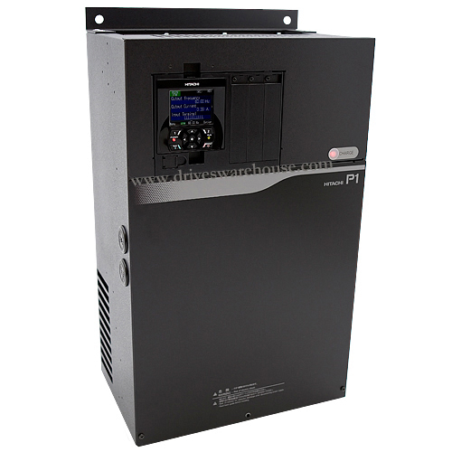
P1-01530-LFUF
about $2500 new. P1-01530-LFUF: Constant Torque Hitachi 40 HP, 30 kW, VFD. then you don't need to bother with the phase converter. hopefully you have a QO panel, you'll need a 125A breaker for this!
the next size up (50HP) is P1-01850-LFUF, about $3k, if you want to spend extra to feel better.
cheapest drive that's IN STOCK is $1,811.68 3ø 25hp (invertek), so you save $700 by running through your (hopefully adequate) rotary. assuming you don't toast a drive with imbalanced input.
or you can hunt for a used SJ700 drive for cheap, but ebay isn't the place right now, you can get a new P1 for the NOS money ebay wants.
I think the concerns are overblown, but the loading for the rectifier section is based on even current. you run into the same problem as single-phasing a 3ø rectifier if the currents are imbalanced, needing larger capacities on the higher voltage phases happens quickly.
you've got the RLA startup, but the torque to drive the load isn't there on a centrifugal fan. the inertia of the fan blades is probably significant on a 25hp fan though.
wouldn't any dual voltage motor have enough leads for that?
re: single phasing a VFD:
using this motor as a reference:
we need 60 amps to run our fan at full power.
based on this chart for single phasing VFDs:
we can probably use the VLD table for our gently started fan, we cross 63.6 amps with the -01530 drive:
P1-01530-LFUF
www.driveswarehouse.com
about $2500 new. P1-01530-LFUF: Constant Torque Hitachi 40 HP, 30 kW, VFD. then you don't need to bother with the phase converter. hopefully you have a QO panel, you'll need a 125A breaker for this!
the next size up (50HP) is P1-01850-LFUF, about $3k, if you want to spend extra to feel better.
cheapest drive that's IN STOCK is $1,811.68 3ø 25hp (invertek), so you save $700 by running through your (hopefully adequate) rotary. assuming you don't toast a drive with imbalanced input.
or you can hunt for a used SJ700 drive for cheap, but ebay isn't the place right now, you can get a new P1 for the NOS money ebay wants.
There are probably some motors that bring out all 12 leads. Most dual voltage motors only bring out 9 leads. A 25 will probably be wired delta and have the corners permanently connected at the winding.
Attachments
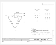
you could still do it with a 9 lead though (?) if you can do it with wire nuts, you could do it with relays (right?). I've never bothered, all our big stuff (25 - 50hp) is either VFD or DOL. everything small is VFD.There are probably some motors that bring out all 12 leads. Most dual voltage motors only bring out 9 leads. A 25 will probably be wired delta and have the corners permanently connected at the winding.
the big issue is probably the transition from Y to ∆ on a big motor with the phase converter. there's an inductive spike when you re-close the spinning motor, far from 60Hz, back on the line. pretty easy to pop breakers re-closing a DOL motor that's under-speed, too.
I'd bet on it being cheaper to use a soft starter than Y-∆ these days anyways.
Last edited:
A 9 lead motor has connections buried in the winding. Either the center wye connection or the corners of a delta. I can't see any way to change that, if you can be my guest.you could still do it with a 9 lead though (?) if you can do it with wire nuts, you could do it with relays (right?). I've never bothered, all our big stuff (25 - 50hp) is either VFD or DOL. everything small is VFD.
the big issue is probably the transition from Y to ∆ on a big motor with the phase converter. there's an inductive spike when you re-close the spinning motor, far from 60Hz, back on the line. pretty easy to pop breakers re-closing a DOL motor that's under-speed, too.
I'd bet on it being cheaper to use a soft starter than Y-∆ these days anyways.
it's a dual voltage motor - maybe it's not a true Y∆, but you could still bring all the leads out into a relay box. I think it's moot with the prices of SSR/triac soft starters.A 9 lead motor has connections buried in the winding. Either the center wye connection or the corners of a delta. I can't see any way to change that, if you can be my guest.
a magnetic/thermal motor starter is $1.5-2.5k for 25hp, soft starter for 25hp is $1k, and above the VFD is $2.5k
You are saying with a 240v supply you would start it with high voltage connection then switch to low voltage connection? I've never heard of that being done but I guess it would work.it's a dual voltage motor - maybe it's not a true Y∆, but you could still bring all the leads out into a relay box. I think it's moot with the prices of SSR/triac soft starters.
a magnetic/thermal motor starter is $1.5-2.5k for 25hp, soft starter for 25hp is $1k, and above the VFD is $2.5k
is that not the core of what star delta starters do?You are saying with a 240v supply you would start it with high voltage connection then switch to low voltage connection? I've never heard of that being done but I guess it would work.
I guess it's very similar. I've just never heard of it being done that way. Without figuring it out I would guess it takes a lot more contacts.is that not the core of what star delta starters do?
A 240v delta wound motor wired in wye would be a 415v motor vs a dual voltage motor in high voltage would be a 480v motor. Would probably have a very similar effect
Strouty
Well-known member
I am really glad I asked the question, this is some interesting info. As for the load on start up, I can spin it easily by hand, not like a hydraulic pump or a direct drive air compressor.
I don't remember how imbalanced my RPC was, but 3% is about 7 volts at 240, regardless, balancing it isn't that tough, just a bit of trial and error.
The blower is for a fume/dust extraction system that I would like to use as a dust collector for sand blasting.
I don't remember how imbalanced my RPC was, but 3% is about 7 volts at 240, regardless, balancing it isn't that tough, just a bit of trial and error.
The blower is for a fume/dust extraction system that I would like to use as a dust collector for sand blasting.
Attachments


I still think you could do it with the normal 4, but I haven't drawn it out. either way free speed is still line speed, and you get a torque reduction in the high voltage configuration. one would need to do the math to make sure torque is adequate for the use case but the formulas aren't hard to find. I think list price makes it irrelevant if you're considering buying new, nevermind complexity and quirks. backfeeding the open transition surge into "the grid" is probably way different than backfeeding it into your local 3ø rotary grid (probably hits way harder in the latter case).I guess it's very similar. I've just never heard of it being done that way. Without figuring it out I would guess it takes a lot more contacts.
A 240v delta wound motor wired in wye would be a 415v motor vs a dual voltage motor in high voltage would be a 480v motor. Would probably have a very similar effect
I really can't say which is better for you, but centrifugals are easy to control running amps with a throttle/restriction, so I wouldn't be afraid to run it on a soft starter to keep the rotary happy and throttle/orifice it if necessary for max power.I am really glad I asked the question, this is some interesting info. As for the load on start up, I can spin it easily by hand, not like a hydraulic pump or a direct drive air compressor.
I don't remember how imbalanced my RPC was, but 3% is about 7 volts at 240, regardless, balancing it isn't that tough, just a bit of trial and error.
The blower is for a fume/dust extraction system that I would like to use as a dust collector for sand blasting.
another thing to keep in mind is a decent VFD will have an energy saving option in the settings, so it'll lower the output voltage to match the load. often works well in underloaded applications (like speed controlling constant torque equipment) and even better with fans (vs normal V/F). both hitachi's P1 and most of the invertek line can do sensorless vector feedback so the VFD knows what's going on without adding a resolver, and I have to say I am amazed at how cool fan motors can run on the inverteks when at low speed.
Last edited:
Strouty
Well-known member
Good info for sure, I won't be setting this up for a while, but I figured I would start with my research now.
I agree, I don't think I would try to do a wye delta or similar. I do think part winding start would be worth considering. It's simple and cheap, even though it's not as effective as wye delta. It sounds like there is already one contactor so he needs one contactor and overload to do it.I still think you could do it with the normal 4, but I haven't drawn it out. either way free speed is still line speed, and you get a torque reduction in the high voltage configuration. one would need to do the math to make sure torque is adequate for the use case but the formulas aren't hard to find. I think list price makes it irrelevant if you're considering buying new, nevermind complexity and quirks. backfeeding the open transition surge into "the grid" is probably way different than backfeeding it into your local 3ø rotary grid (probably hits way harder in the latter case).
I really can't say which is better for you, but centrifugals are easy to control running amps with a throttle/restriction, so I wouldn't be afraid to run it on a soft starter to keep the rotary happy and throttle/orifice it if necessary for max power.
another thing to keep in mind is a decent VFD will have an energy saving option in the settings, so it'll lower the output voltage to match the load. often works well in underloaded applications (like speed controlling constant torque equipment) and even better with fans (vs normal V/F). both hitachi's P1 and most of the invertek line can do sensorless vector feedback so the VFD knows what's going on without adding a resolver, and I have to say I am amazed at how cool fan motors can run on the inverteks when at low speed.
454ragtop
Well-known member
I've had a VFD on my Jet 12 X 36 lathe for years, just controlling it with the keypad. This week I hooked it up to the OEM control on the apron, and added a speed pot. Should have done it years ago, so much nicer. When I got the lathe from a school surplus sale, it was missing the apron switches and control parts, had to buy another whole lathe to get them. The new VFD controls work so nice I got my 5C collet setup all dialed in amd working.
Attachments


whateg01
Well-known member
That speed pot really makes a difference in ease of use.I've had a VFD on my Jet 12 X 36 lathe for years, just controlling it with the keypad. This week I hooked it up to the OEM control on the apron, and added a speed pot. Should have done it years ago, so much nicer. When I got the lathe from a school surplus sale, it was missing the apron switches and control parts, had to buy another whole lathe to get them. The new VFD controls work so nice I got my 5C collet setup all dialed in amd working.

slodat
ALLIANCE MEMBER
I didn’t realize LS made drives. We use a lot of LS power breakers in retrofit projects. Looks good!
sparkness
Well-known member
My Bandsaw VFD 1940's Yates American
I have a mitsubishi 110V 1/2 HP VFD powering a 3/4 HP motor , works perfect I have 3 speed settings 80, 250, 300 SFM as I converted this to metal cutting
I have a mitsubishi 110V 1/2 HP VFD powering a 3/4 HP motor , works perfect I have 3 speed settings 80, 250, 300 SFM as I converted this to metal cutting
Attachments


RichieP_MechE
Well-known member
This Delta Rockwell 15-655 drill press spent its life in the Carnegie Mellon University School of Architecture woodshop. It appeared on facebook marketplace last August, and for 100 bucks I couldn't pass it up. With a 3 phase, 3/4 horse motor it made a good candidate for a vfd convertion.
First, a picture of the finished product:

This was the condition I received it in. It had been in storage for years and seemed like it had been under a leaky sprinkler pipe based on the rust and water stains on the table. The head and table had been lowered to make it easy to move. It took some effort to remove the head from the column, though in retrospect I should have just pulled the column from the base first and dropped the head off the bottom instead of pushing it all the way up to the top.

I disassembled everything for cleaning. I like patina on my equipment so I just got rid of the surface rust and gave it a degreaser bath. I'm not a big fan of the CVT drive system on these (they are pretty noisy) and I also intend to use this for metalworking only (mostly running countersinks), so I removed the drive and replaced it with some standard pulleys, with the VFD serving as the new speed control. The pulley reduction is about 2/3 for a max spindle speed of 1200 rpm. Unfortunately for those looking for spare parts, I accidentally damaged the top half of each of the old CVT pulley sets when removing them.

For a VFD, I used a Lenze SMV series 1 hp VFD. I wanted to wire it for 120V, however all of my 120V circuits are GFCI protected and were tripped by the VFD in my initial tests. So this is wired for 240V AC. The disconnect is an ABB branded one that I got in some auction electronics surplus, which I housed in a plastic enclosure. Everything is mounted to the original bracket that used to hold the motor contactor.

The control panel is definitely my favorite part of this build. The tachometer is a cheap 0-10VDC volt meter that I printed a new dial for. It's connected to the 0-10V output of the VFD, which is tied to the position of the potentiometer knob. There's a locking switch for forward/reverse selection (though I don't know how well reverse is going to work with the keyless chuck) The blue anodized aluminum panel was designed by me and fabricated by Front Panel Express.

Some detail inside the panel. I 3D printed a custom bracket that attaches to the modular start/stop switch and mounts these tiny little terminal blocks I found from Phoenix Contact. In the upper portion of the image, you can also see some of the adapter plate I designed to adapt this panel to the original power switch mounting point. The adapter plate was fabricated by SendCutSend.

I also added a fan for some extra cooling when running this thing at lower speeds. It's powered by the main disconnect. The lowest frequency this can run at without stalling seems to be about 5 Hz which is equivalent to around 90 rpm.

I also kept all the hand-written sharpie marks on it - this was a in a student shop so everything was labeled. This is definitely some architect's handwriting!

Here's a short demo of it in operation:
First, a picture of the finished product:
This was the condition I received it in. It had been in storage for years and seemed like it had been under a leaky sprinkler pipe based on the rust and water stains on the table. The head and table had been lowered to make it easy to move. It took some effort to remove the head from the column, though in retrospect I should have just pulled the column from the base first and dropped the head off the bottom instead of pushing it all the way up to the top.
I disassembled everything for cleaning. I like patina on my equipment so I just got rid of the surface rust and gave it a degreaser bath. I'm not a big fan of the CVT drive system on these (they are pretty noisy) and I also intend to use this for metalworking only (mostly running countersinks), so I removed the drive and replaced it with some standard pulleys, with the VFD serving as the new speed control. The pulley reduction is about 2/3 for a max spindle speed of 1200 rpm. Unfortunately for those looking for spare parts, I accidentally damaged the top half of each of the old CVT pulley sets when removing them.
For a VFD, I used a Lenze SMV series 1 hp VFD. I wanted to wire it for 120V, however all of my 120V circuits are GFCI protected and were tripped by the VFD in my initial tests. So this is wired for 240V AC. The disconnect is an ABB branded one that I got in some auction electronics surplus, which I housed in a plastic enclosure. Everything is mounted to the original bracket that used to hold the motor contactor.
The control panel is definitely my favorite part of this build. The tachometer is a cheap 0-10VDC volt meter that I printed a new dial for. It's connected to the 0-10V output of the VFD, which is tied to the position of the potentiometer knob. There's a locking switch for forward/reverse selection (though I don't know how well reverse is going to work with the keyless chuck) The blue anodized aluminum panel was designed by me and fabricated by Front Panel Express.
Some detail inside the panel. I 3D printed a custom bracket that attaches to the modular start/stop switch and mounts these tiny little terminal blocks I found from Phoenix Contact. In the upper portion of the image, you can also see some of the adapter plate I designed to adapt this panel to the original power switch mounting point. The adapter plate was fabricated by SendCutSend.
I also added a fan for some extra cooling when running this thing at lower speeds. It's powered by the main disconnect. The lowest frequency this can run at without stalling seems to be about 5 Hz which is equivalent to around 90 rpm.
I also kept all the hand-written sharpie marks on it - this was a in a student shop so everything was labeled. This is definitely some architect's handwriting!
Here's a short demo of it in operation:
whateg01
Well-known member
I like the fan addition! I've been meaning to add one to the motor in my lathe for the same reason but in the 4 or 5 years I've had it set up like this, I've never gotten a round tuit. So far it hasn't been an issue, but it's still on the to do list.I also added a fan for some extra cooling when running this thing at lower speeds. It's powered by the main disconnect. The lowest frequency this can run at without stalling seems to be about 5 Hz which is equivalent to around 90 rpm.
bpwoodworking
Well-known member
- Joined
- Jul 6, 2023
- Messages
- 254
That is hilarious that the shop teacher wrote 'Drill Press' on the side of it. Nicely written, most likely the guy learned how to letter in drafting class.
I've done a few of these, one on my tablesaw, another on my drill press. Using Hitachi WJ200 inverters.
On the drill press I added an aluminum stand and attached an electrical box to that where all of the controls are mounted. I use pushbutton switches.
I have students so I wanted to make sure that I would have the proper E-switches on these machines and wanted them to slow down rapidly. Both stop in 2 seconds. For that on the tablesaw, especially with a dado stack, added a resistor. For the saw I added one at knee height on the front and another under the slider.
On the tablesaw I changed the motor as well, this machine was imported into the US and in doing so they removed the european motor and replaced it with a comparably sized (physical size) baldor which was 1.5hp. This is too small for my purposes and so I installed a 3hp 90L frame motor from Lafert. Lafert makes high quality motors so it is equal to, or likely better, than the motor used from Germany.
Duker
Well-known member
Nice... also... what's the project in walnut you got going on there....?That is hilarious that the shop teacher wrote 'Drill Press' on the side of it. Nicely written, most likely the guy learned how to letter in drafting class.
I've done a few of these, one on my tablesaw, another on my drill press. Using Hitachi WJ200 inverters.
On the drill press I added an aluminum stand and attached an electrical box to that where all of the controls are mounted. I use pushbutton switches.
I have students so I wanted to make sure that I would have the proper E-switches on these machines and wanted them to slow down rapidly. Both stop in 2 seconds. For that on the tablesaw, especially with a dado stack, added a resistor. For the saw I added one at knee height on the front and another under the slider.
On the tablesaw I changed the motor as well, this machine was imported into the US and in doing so they removed the european motor and replaced it with a comparably sized (physical size) baldor which was 1.5hp. This is too small for my purposes and so I installed a 3hp 90L frame motor from Lafert. Lafert makes high quality motors so it is equal to, or likely better, than the motor used from Germany.
Firebrick43
Well-known member
Be careful turning that motor down that far. They don’t recommend running non inverter rated motors below 20hz. The way inverters form the wave forms causes very high voltage spikes. This will blow holes in the insulation of the motor windings. Inverter rated motors have a higher class of insulation to deal with those spikes.This Delta Rockwell 15-655 drill press spent its life in the Carnegie Mellon University School of Architecture woodshop. It appeared on facebook marketplace last August, and for 100 bucks I couldn't pass it up. With a 3 phase, 3/4 horse motor it made a good candidate for a vfd convertion.
First, a picture of the finished product:
This was the condition I received it in. It had been in storage for years and seemed like it had been under a leaky sprinkler pipe based on the rust and water stains on the table. The head and table had been lowered to make it easy to move. It took some effort to remove the head from the column, though in retrospect I should have just pulled the column from the base first and dropped the head off the bottom instead of pushing it all the way up to the top.
I disassembled everything for cleaning. I like patina on my equipment so I just got rid of the surface rust and gave it a degreaser bath. I'm not a big fan of the CVT drive system on these (they are pretty noisy) and I also intend to use this for metalworking only (mostly running countersinks), so I removed the drive and replaced it with some standard pulleys, with the VFD serving as the new speed control. The pulley reduction is about 2/3 for a max spindle speed of 1200 rpm. Unfortunately for those looking for spare parts, I accidentally damaged the top half of each of the old CVT pulley sets when removing them.
For a VFD, I used a Lenze SMV series 1 hp VFD. I wanted to wire it for 120V, however all of my 120V circuits are GFCI protected and were tripped by the VFD in my initial tests. So this is wired for 240V AC. The disconnect is an ABB branded one that I got in some auction electronics surplus, which I housed in a plastic enclosure. Everything is mounted to the original bracket that used to hold the motor contactor.
The control panel is definitely my favorite part of this build. The tachometer is a cheap 0-10VDC volt meter that I printed a new dial for. It's connected to the 0-10V output of the VFD, which is tied to the position of the potentiometer knob. There's a locking switch for forward/reverse selection (though I don't know how well reverse is going to work with the keyless chuck) The blue anodized aluminum panel was designed by me and fabricated by Front Panel Express.
Some detail inside the panel. I 3D printed a custom bracket that attaches to the modular start/stop switch and mounts these tiny little terminal blocks I found from Phoenix Contact. In the upper portion of the image, you can also see some of the adapter plate I designed to adapt this panel to the original power switch mounting point. The adapter plate was fabricated by SendCutSend.
I also added a fan for some extra cooling when running this thing at lower speeds. It's powered by the main disconnect. The lowest frequency this can run at without stalling seems to be about 5 Hz which is equivalent to around 90 rpm.
I also kept all the hand-written sharpie marks on it - this was a in a student shop so everything was labeled. This is definitely some architect's handwriting!
Here's a short demo of it in operation:
Very nice job with your implementation!