To avoid these ads, REGISTER NOW!

Show us your welding projects

ZTFab

Well-known member
Joined
Jan 6, 2008
Messages
397
Location
Upland, CA
Here's a project I knocked out today.

These are air cleaner covers for a Manx buggy that my brother-in-law owns. He's running aftermarket filters on his dual carb setup and wanted some aluminum covers for them.

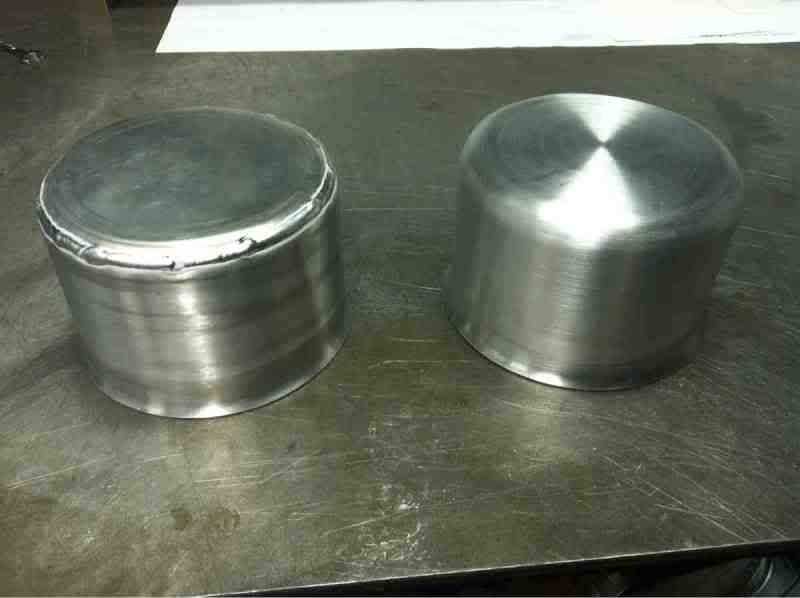
I used .050" 5052-H32 aluminum and formed them using my slip roll and bead roller with "tank-roll" dies. They measure 6" in diameter and 4" tall.

They are made in two pieces. I rolled the bottom portion on the slip roll and **** welded it together, then formed the lower bell and then the upper half radius on the bead roller. Then I cut a circle for the top and formed the radius on the edge using the bead roller again.

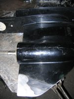
After welding the two pieces together I chuck the piece in my lathe to hold it while I shave the weld down with a file then finish with emery cloth.

Photos_0-4.jpg


Photos_1-6.jpg


Photos_3-4.jpg


Photos_6-3.jpg


Photos_8-2.jpg


Photos_11-1.jpg
 
To avoid these ads, REGISTER NOW!

monkers

Well-known member
Joined
Nov 30, 2009
Messages
159
as ususal ZT, very nice work. What is the deciding factor in your choice of alum alloy, certain grades form better than others I assume? great work!
 

jkm4874ford

Well-known member
Joined
Nov 20, 2011
Messages
58
Location
Bowling Green, ky
Hoping it works out today. These are pics of a 48 Ford truck frame we have been working on. Four link rear and independant front.
 

Attachments

  • Picture 831.jpg
    Picture 831.jpg
    80.2 KB · Views: 916
  • IMG_2431.JPG
    IMG_2431.JPG
    85.5 KB · Views: 839
  • Picture 847.jpg
    Picture 847.jpg
    76.2 KB · Views: 870
  • IMG_2433.JPG
    IMG_2433.JPG
    85.4 KB · Views: 862
  • IMG_2432.JPG
    IMG_2432.JPG
    80.8 KB · Views: 705
  • IMG_2435.JPG
    IMG_2435.JPG
    81 KB · Views: 629

jkm4874ford

Well-known member
Joined
Nov 20, 2011
Messages
58
Location
Bowling Green, ky
Nice work but why is the 4-link installed upside down?[/QUOTE]


We were left to our own for the install. I have seen them this way. But you now have me second guessing myself.
 

ibedayank

Well-known member
Joined
Feb 2, 2011
Messages
2,619
Location
Columbia TN

Mario428

Well-known member
Joined
Dec 4, 2009
Messages
156
Location
PEI, Canada
Nice work but why is the 4-link installed upside down?


We were left to our own for the install. I have seen them this way. But you now have me second guessing myself.[/QUOTE]

For a relatively low power application like I assume yours is maybe does not matter that much. You are going to want your links parallel with the bars at a 5ish degrees down.
Would like to see how the rear brackets are attached.
Looks like a fairly basic drag race car kit you used, idea is the top bar has most of the adjustment so the larger number of holes go up.
Would also like to see that tubing coming out of the frame gusseted some, lot of fore and aft strain on that part which will flex the thin wall of the frame rail.
Sorry I ruined your day.
 

jkm4874ford

Well-known member
Joined
Nov 20, 2011
Messages
58
Location
Bowling Green, ky
It will be relatively low power, 300-350 HP max.

As far as gusseting the tube goes thru and welds in the the interior boxing member.

Thanks for the comments.
 

hunter1151

Well-known member
Joined
Jun 19, 2011
Messages
202
Location
Kansas
We were left to our own for the install. I have seen them this way. But you now have me second guessing myself.

For a relatively low power application like I assume yours is maybe does not matter that much. You are going to want your links parallel with the bars at a 5ish degrees down.
Would like to see how the rear brackets are attached.
Looks like a fairly basic drag race car kit you used, idea is the top bar has most of the adjustment so the larger number of holes go up.
Would also like to see that tubing coming out of the frame gusseted some, lot of fore and aft strain on that part which will flex the thin wall of the frame rail.
Sorry I ruined your day.[/QUOTE]

Those coilovers will rip those brackets right off of that tubing in no time. I'm speaking from experience here..........that tube looks way too small. JMHO
 

Mario428

Well-known member
Joined
Dec 4, 2009
Messages
156
Location
PEI, Canada
Those coilovers will rip those brackets right off of that tubing in no time. I'm speaking from experience here..........that tube looks way too small. JMHO

Not sure I agree with that statement, took another look and the welding seems up to par without a personal visit.
Have seen lots of drag cars done the same way that work the shocks hard and never have a problem.
 

hunter1151

Well-known member
Joined
Jun 19, 2011
Messages
202
Location
Kansas
Check out Carrol Smith's book "Prepare to Win" for the proper design of that particular gusset. I bet Nasty would back me up on this one.........
 

NASTYZEN

Well-known member
Joined
Jun 11, 2010
Messages
2,823
Location
St-Colomban,Que. Canada
You can't go wrong with that book, like Hunter suggested.:thumbup:

I rarely work on that type of suspension and never noticed the booboo, good eye jkm4874ford.

Another good book I use is ''How To Make Your Car Handle'' by Fred Puhn.

I'm all for some more gusseting as well, can't hurt and can add some 'pretty' to your project if done ZT style.
 

cbacres

Well-known member
Joined
May 28, 2010
Messages
5,998
Location
SW Florida
Heres a simple project I knocked out today. Simple compared to the craftsmanship I've seen here.
Modified a frame with casters to match my Miller 330 welder. Picked up the frames for $ 5.00 each, so it was worth the time to cut and weld back together.

Welder weighs about 600 lbs, wheels are necessary.
 

Attachments

  • DSC04048.jpg
    DSC04048.jpg
    91.6 KB · Views: 452
  • DSC04067.jpg
    DSC04067.jpg
    75.3 KB · Views: 448
  • DSC04065.jpg
    DSC04065.jpg
    84 KB · Views: 417
  • DSC04064.jpg
    DSC04064.jpg
    83.5 KB · Views: 445

hackster

Active member
Joined
Aug 9, 2011
Messages
30
Some great stuff on here, I just wasted an entire evening reading through the 11 pages of cool projects.....I am an amateur fabricator on some pretty fun projects.

Here is the last build from last winter. The toyota started as a 2wd daily driver that would not run or pass emissions here, got it for a steal from a co worker.

Start....

tacomaswap015.jpg


Front end work is just about done

TacomaSwap088.jpg


That bed is going to get destroyed....might as well build a new one now.

IMG_0590.jpg


IMG_0602.jpg


IMG_0598.jpg


IMG_0613.jpg


IMG_0615.jpg


IMG_0712.jpg
 

hackster

Active member
Joined
Aug 9, 2011
Messages
30
Thanks.

No plans for an exo. This rig is mostly built for winter time wheeling here in the Pacific Northwet. It sees lots of snow duty and the occasional expedition.

I have a buggy that I use during the less wet months of the year that gets beat on quite a bit.

waterfalljeep.jpg


calscrackjeep.jpg


I have some rebuild pics around here somewhere of the buggy....

buggy1.jpg


buggy2.jpg
 

ZTFab

Well-known member
Joined
Jan 6, 2008
Messages
397
Location
Upland, CA
This may count as double dipping from my Resto thread, but here's how I attached a '02 Trans Am front suspension to my '54 F100 Frame:

I really hope you take what I'm about to say as constructive criticism, and it is only my opinion, but the way you mounted that k-member is sketchy at best.

There is almost no lateral support....in other words, one good turn or bump with that truck and it will almost certainly move if not break off.

You need to use more contact surface area for the mounts to spread the loads and use some boxing and/or gussets for triangulation. Also, the single bolts holding the front either need more bolts or the mount needs to be welded to the frame.

Also, the welds on the rear mounting tubes were done "downhill" and and need to be looked at closely. I'm not saying they will fail but vertical MIG welds are usually best when done "uphill". I do vertical downhill welds on occasion but I have been welding for more than a decade.

I know you are learning a lot while doing this resto and that's great....this is all part of the learning and I hope you don't take offense to my opinion on your work.
 
To avoid these ads, REGISTER NOW!

z28snksknr

Well-known member
Joined
Jul 8, 2009
Messages
1,827
Location
Turnersville, NJ
I really hope you take what I'm about to say as constructive criticism, and it is only my opinion, but the way you mounted that k-member is sketchy at best.

There is almost no lateral support....in other words, one good turn or bump with that truck and it will almost certainly move if not break off.

You need to use more contact surface area for the mounts to spread the loads and use some boxing and/or gussets for triangulation. Also, the single bolts holding the front either need more bolts or the mount needs to be welded to the frame.

Also, the welds on the rear mounting tubes were done "downhill" and and need to be looked at closely. I'm not saying they will fail but vertical MIG welds are usually best when done "uphill". I do vertical downhill welds on occasion but I have been welding for more than a decade.

I know you are learning a lot while doing this resto and that's great....this is all part of the learning and I hope you don't take offense to my opinion on your work.

My reason for posting this here was to get this exact type of feedback. I've never done this type of work before, so I need all the help I can get :thumbup:. I plan on adding 2 additional bolts to the front plates to better secure them, but I ran out of steam (and time) before snapping those pics.


The following is offered to spur more discussion, not a rebuttal to your points (aka this is not me being defensive, just giving my perspective and some addtional info not apparent in the pic): The mounting scheme for the car this came out of from the factory ('02 trans am WS6) is nearly identical to this - 6 bolts through the k-member into a 16ga. steel subframe and no other gussets or bracing to speak of (I do need to fab up the mounts for hte rear 2 bolts still). The mounting locations of the k-member do not contact more area in the original application than I've created here. I've owned and driven a 4th gen F-body for 13 years and know a lot about them and I've never heard of any 4th gen F-body owners claiming that they broke their k-member bolts. I'm using the same size and thread of the factory bolts, grade 8.

The upper strut mounts would be the main load points here, am I right? They carry all the vertical load of the vehicle, so there is not a tremendous load on the k-member to frame mounts in my opinion. What's not shown here (because I haven't installed them yet) is the upper strut mount. That I am purchasing from Ballistic Fabrication who specializes in custom suspension mounts (mainly for the 4x4 community).

Can you elaborate at to why welding from the top down is not as good as from the bottom up? It's the same heat and filler material, so I'm puzzled why welding direction would affect it's strength.

I really do appreciate your feedback (no sarcasm here). Please let me know if what I offered here as an explanation does not satisfy your concerns.
 
Last edited:

z28snksknr

Well-known member
Joined
Jul 8, 2009
Messages
1,827
Location
Turnersville, NJ
By the way, you have me second guessing (again) my use of the front mounts which is all I need to convince me to mimic my rear mounts there. My thread goes into more detail, but I wasn't completely convinced that they were the best option. You've given me the push I needed to change them over to match the rears.
 

NASTYZEN

Well-known member
Joined
Jun 11, 2010
Messages
2,823
Location
St-Colomban,Que. Canada
At a min. I would do this. Actually put two more bolts side by side and a bit lower than my scetch.
Maybe weld that bracket all around.
The rear bracket has a long contact, so it shouldn't matter that you went down hill.
Your use for this truck should dictate how your going to put it together. If your gonna go 500 HP vrs 150 makes a difference.....

clipdz.jpg
 

omr

Banned
Joined
Jun 1, 2011
Messages
723
If you have ever seen any of ztfabs work you would be inclined to take his advice.

Welding down hill tends to let the puddle get ahead of you, If you're not careful this can effect penetration or not leave enough filler.

As far as the mounts go, they may be fine, but the stock set up on the car doesnt hang down and create leverage.

I would personally be worried about the frame cracking where you welded the mounts.

Another thing that may or may not be accurate but i have always believed, I never like to weld vertically on a frame. On the rear mount you have pictured, I would weld the top and then from the back i would weld the bottom, along with two bolts and two gussets like, nastyzen posted.
 
Last edited:

bggrnchvy

Well-known member
Joined
Nov 14, 2011
Messages
579
Location
Pleasant Hill, CA
I'm far from a professional, but I do have quite a few items I've managed to hot metal glue together in the last several years.

Most recently was this patio/step for the truck when I'm not yanking the trailer around. Works nicely to haul the cooler and some gas cans, though I wish I'd had the camper on the truck to measure when I started so I could have raised it a couple of inches.

2011-10-16_14-31-04_576.jpg

2011-11-23_08-19-08_898.jpg

2011-11-25_13-28-00_322.jpg


I'm really only a design guy at work, but we needed a cooling tower designed and built and we have the tools so I took a crack at it. It was kind of fun making a model, prints and notes all for myself to follow. When I was fabricating and cussing, it was all my own fault:lol:

2011-04-25_11-54-43_377.jpg

2011-04-20_11-55-37_15.jpg

2011-11-01_10-16-55_297.jpg


It came out pretty close to the model:
1637_ISO.jpg


There's always the Chevy project...I mean always, it won't stop:(

297660_2266016282415_1008765435_2574967_195552399_n.jpg


I built some drive-over tubes for my buddies trailer as pulling the fenders all the time was getting old:

101_0109.jpg


I built a storage saver for the garage out of some simple box tube and plywood:
101_0051.jpg


Winch bumper for an XJ a while back. I built a rear one as well:
ReedsBumper09007.jpg


The welding cart with the hydraulic converted bender on top. I don't know if I could get along without it.

BenderCartDay.jpg
 

z28snksknr

Well-known member
Joined
Jul 8, 2009
Messages
1,827
Location
Turnersville, NJ
At a min. I would do this. Actually put two more bolts side by side and a bit lower than my scetch.
Maybe weld that bracket all around.
The rear bracket has a long contact, so it shouldn't matter that you went down hill.
Your use for this truck should dictate how your going to put it together. If your gonna go 500 HP vrs 150 makes a difference.....

clipdz.jpg

After thinking on this for a bit yesterday and taking the advice given, I will be replacing these front and rear mounts completely. I plan on taking some 3" x .25" wall square tubing and cutting a "saddle" out of it that will be welded to the full width of the bottom of the frame and up both sides a bit. For the life of me, I can't get over why I didn't do it that way from the start - I know better and I have the tubing sitting around in the garage already...

If you have ever seen any of ztfabs work you would be inclined to take his advice.
Welding down hill tends to let the puddle get ahead of you, If you're not careful this can effect penetration or not leave enough filler.

As far as the mounts go, they may be fine, but the stock set up on the car doesnt hang down and create leverage.

I would personally be worried about the frame cracking where you welded the mounts.

Another thing that may or may not be accurate but i have always believed, I never like to weld vertically on a frame. On the rear mount you have pictured, I would weld the top and then from the back i would weld the bottom, along with two bolts and two gussets like, nastyzen posted.


Oh, I agree 100% - I posted to learn from these guys and I hold both NASTYZEN and ZTFAB in very high regard. I just like to understand the "why" for the next time I do it, so I ask questions. I never would have thought that welding from the bottom up would be better than the top down, but I learned why today. Now I know :thumbup:

Thanks again, to all that pitched in. I'll post my revisions once I get out there and fix my rookie mistakes :(!

:beer:
 
Last edited:

z28snksknr

Well-known member
Joined
Jul 8, 2009
Messages
1,827
Location
Turnersville, NJ
Here's my new plan - The dotted lines show the rest of the tubing and the whole thing will be fully welded to the frame- no bolts. The rear will get the same treatment, but I'll have to trim away the square tubing I already welded in. Thoughts?

View media item 13595
 

omr

Banned
Joined
Jun 1, 2011
Messages
723
There is nothing wrong with using bolts at all.

If you take nastyzens advice and add two gussets and two bolts to the rear mount you already have with a weld on the top and a weld on the bottom i think it would strong as hell.

I personally don't like to make vertical welds on a frame because i have seen quite a few cause the frame to crack, welding horizontally doesn't bother me at all and isnt likely to cause any issues.
 

Rezarf

Well-known member
Joined
Jul 16, 2011
Messages
211
The welding cart with the hydraulic converted bender on top. I don't know if I could get along without it.

BenderCartDay.jpg

Looks awesome bro! Got any threads on building that cart/bender setup? I am trying to consolidate my welder and JD2 Model 3 into a mobile workstation around my 3 bay.

I would love to see some more shots of it. Perhaps a new thread is in order? :beer:
 

ZTFab

Well-known member
Joined
Jan 6, 2008
Messages
397
Location
Upland, CA
Here's my new plan - The dotted lines show the rest of the tubing and the whole thing will be fully welded to the frame- no bolts. The rear will get the same treatment, but I'll have to trim away the square tubing I already welded in. Thoughts?

I would build mounts something like this:


It's just a quick part I made in SolidWorks to show you the concept. I would start with the lower mounting plate and bolt it to the K-member with a captive nut (just like you have on your existing front mount) and make sure the plate contacts the K-member as much as possible...that means you may have to bend it to fit.

Then make the inner frame piece and tack it or clamp it on, then make templates for the side pieces to fit to the contour of the frame, and finally the top piece to fit the side pieces.

Also, the way you have the rear tube open at the top will trap water and debris and eventually rust that piece out over time.
 
Last edited:

KrucksGarage

Well-known member
Joined
Jul 10, 2011
Messages
400
Location
Washington State
These are some great welding projects guys. I'm new here and having a blast so far looking through your forum on all these topics. I'm a welder by trade, working for Submarine Base Bangor up here in Silverdale, WA. I enjoy doing fabrication hobbies on the side at home also. Right now I'm working on a 1976 Jeep CJ5, among other projects. I'll try and attach a few pictures of the frame I built recently. I never took close ups of welds so I will try and get a few of those to add later. Keep up the great projects fellas, a lot of fun to see everyones creativity!
 

Attachments

  • P1020249 [1024x768].jpg
    P1020249 [1024x768].jpg
    86.9 KB · Views: 508

omr

Banned
Joined
Jun 1, 2011
Messages
723
There is nothing wrong with using bolts at all.

If you take nastyzens advice and add two gussets and two bolts to the rear mount you already have with a weld on the top and a weld on the bottom i think it would strong as hell.

I personally don't like to make vertical welds on a frame because i have seen quite a few cause the frame to crack, welding horizontally doesn't bother me at all and isnt likely to cause any issues.

Im sorry the mount you have pictured is the front not the rear, guess i should have seen the sway bar..lol
 

bggrnchvy

Well-known member
Joined
Nov 14, 2011
Messages
579
Location
Pleasant Hill, CA
Looks awesome bro! Got any threads on building that cart/bender setup? I am trying to consolidate my welder and JD2 Model 3 into a mobile workstation around my 3 bay.

I would love to see some more shots of it. Perhaps a new thread is in order? :beer:

I think I did on another forum that's since disapeared. I might still have the picture progression, I'll have to see what I can put together. It's nothing extensive really: Hayden 1hp hydro power pack, 2-way log splitter valve, 3x24 double ended ram and some hoses, turned bushings and a frame. To be honest I'm working on a REV02, there are some serious faults with this one.

bggrnchvy, those H2s go on your Ram??

They are, nice guess:thumbup: Was it the offset and stickout?
 

GirlnAgarage

Well-known member
Joined
Jan 21, 2011
Messages
4,668
Location
Texas
They are, nice guess:thumbup: Was it the offset and stickout?


Actually I saw the tread pattern on the tires in the hitch rack pics and compared to the tread in the H2 pics. Couple that with the Ram HD being the only 8lug truck in your arsenal that I could see...elementary my dear Watson. Plus I'm running them on my Ram :D

Edit: hah! Your Chevy is reworked - I see the 8lug under there now. ;)

I see a lot of curves in your metal fab work, What kind of bender do you use for the tubing?
 

bggrnchvy

Well-known member
Joined
Nov 14, 2011
Messages
579
Location
Pleasant Hill, CA
Actually I saw the tread pattern on the tires in the hitch rack pics and compared to the tread in the H2 pics. Couple that with the Ram HD being the only 8lug truck in your arsenal that I could see...elementary my dear Watson. Plus I'm running them on my Ram :D

Edit: hah! Your Chevy is reworked - I see the 8lug under there now. ;)

I see a lot of curves in your metal fab work, What kind of bender do you use for the tubing?

Actually the Chevy is 8 lug as well, but it would be kind of funny looking sitting above those little 35's:lol:

I use a Pro-Tools 105HD running off a cylinder that's on top of that yellow cart at home or the Baileigh RDB-125 at work. The Baileigh has a full set of round and square 270* dies from 1" to 2" while I only have a 1-1/2" and 1-3/4" 270* for my Pro-Tools unit.
 

charger891

Well-known member
Joined
Jan 19, 2011
Messages
91
Location
manitoba
At a min. I would do this. Actually put two more bolts side by side and a bit lower than my scetch.
Maybe weld that bracket all around.
The rear bracket has a long contact, so it shouldn't matter that you went down hill.
Your use for this truck should dictate how your going to put it together. If your gonna go 500 HP vrs 150 makes a difference.....

clipdz.jpg

I didn`t get back to you on your truck restore thread because i didn`t want to tick you off, i`ll try to explain the 2 ways i would have done it, depending on the ttruck height you want to achieve, if you want more ground clearance i`d leave it exhactly where you have it, take some cardboard and trace out the frame (horisontly) and contour the suspension, this then would be your side plate, i`d then substract the thickness of material your using and remove that along the suspension contour at the bottom of the plate, what i would do next is make a plate that contours the suspension top and is wide enough so it would lign up with the inner part of the frame,this plate would then get welded to the side plate, if you wan you can weld the side plates and box the inner part of the frame together then bolt the suspension to the bottom plate.
 

charger891

Well-known member
Joined
Jan 19, 2011
Messages
91
Location
manitoba
the other wau you can do this is if the height allows this is to cut a section of the frame out and build a pocket, you would again grab cardboard and trace out the top of the suspension, percisely measuring the distance, trace the suspension outline onto the outside of the frame, with absolutely no load on the front frame, cut the bottom section of frame out, get yourself a plate that is wide enough to contour the top of the suspension and is long enough to go to the inside of the frame, mark and drill holes for suspension, weld nuts or make stakepocket for suspension nuts, weld this to your bottom side of the frame, box in inside of frame to suspension plate, bolt it in and your done, would be kinda similar to installing a volare suspension.
 
To avoid these ads, REGISTER NOW!
Top Bottom