To avoid these ads, REGISTER NOW!

The Everything 3D Printer Thread

gte718p

Well-known member
Joined
Mar 12, 2009
Messages
3,950
It’s alive. Still waiting on the bed heater. The mcu errors out of it doesn’t get a temp reading from the bed. I had a spare hot end floating around so it is hanging off the back right now.

Still have lots of timing to get it dialed in, but I’m stoked.
 

Attachments

  • 94E67036-2FA4-46AC-81A1-2D9AD4177E67.jpeg
    94E67036-2FA4-46AC-81A1-2D9AD4177E67.jpeg
    286.9 KB · Views: 211
  • 5B7CE101-50B8-412D-A9DE-74FAD4772A49.jpeg
    5B7CE101-50B8-412D-A9DE-74FAD4772A49.jpeg
    357.6 KB · Views: 135
To avoid these ads, REGISTER NOW!

Keyblazer

Well-known member
Joined
Jul 30, 2009
Messages
1,471
Location
Irvine, CA
Was in the middle of a big print(74hrs} on my Ender 3 v2, and sometime overnight at about 45 hours, the extruder stopped working.
I'd just upgraded to the Ender direct drive unit, so I was ticked off...
But after some testing, swapping wires, the extruder is fine.
Looks like I lost the extruder drive on the Motherboard... its not outputting.
My MB is v2.2.
Is it just easier to get the v2.7 and move on?
 

Jehannum

Well-known member
Joined
May 3, 2012
Messages
1,347
Location
Albuquerque, NM
The boy wanted to print TPU, which involves swapping up to a direct drive extruder, so after ordering the wrong one (they come in left hand and right hand drive) from Amazon, I ended up designing my own mount and fan duct for the CR-10. Not much available for the LH BMG extruder, BL Touch, and e3d v6 all in one go that isn't awfully floppy.

It worked out pretty well, and the TPU goes through it like a dream.

IMG_20220707_064238532.jpg
 

Jehannum

Well-known member
Joined
May 3, 2012
Messages
1,347
Location
Albuquerque, NM
Was in the middle of a big print(74hrs} on my Ender 3 v2, and sometime overnight at about 45 hours, the extruder stopped working.
I'd just upgraded to the Ender direct drive unit, so I was ticked off...
But after some testing, swapping wires, the extruder is fine.
Looks like I lost the extruder drive on the Motherboard... its not outputting.
My MB is v2.2.
Is it just easier to get the v2.7 and move on?
Honestly, the mainboards from Creality are kind of ****. I've had all of them fail in one way or another. The worst was when the bed MOSFET shorted to closed and ran away the bed heater on my Ender 3.

I really like my Paquette engineering board. TH3D sells it as their "ezboard", and I've had one now for about 2 years. It's built with enough copper in the board that the drivers don't need heat sinks, it's got TMC2209 drivers so it's dead quiet, does dual Z motors out of the box, and they've got a pretty wicked firmware compiler website that allows you to upload a configuration.h file and get back the firmware in minutes. Plus, they've got loads of storage, so you're not picking and choosing features to include so that you can fit in the babyduino's 128K of system memory.
 

bugnut

ALLIANCE MEMBER
Joined
Jul 14, 2012
Messages
3,834
Location
Central Ohio
So I have been playing with the 3d prusa. Loganb struck a chord with toolbox organization. I have fabricated and entire drawer of organizers for the 1/4, 3/8 and 1/2 drive hardware. None specific to sockets but all to hold various extensions and ratchets.
From there i have migrated to the SAE wrench drawer. I have never been a fan of the commercially available wrench organizers as they do not function as i'd like. So on to printing! also continued next post
 

Attachments

  • 20220609_093837.jpg
    20220609_093837.jpg
    372.4 KB · Views: 137
  • 20220601_133004.jpg
    20220601_133004.jpg
    418.6 KB · Views: 139
  • 20220601_132950 - Copy.jpg
    20220601_132950 - Copy.jpg
    391.7 KB · Views: 137
  • 20220521_115652 - Copy.jpg
    20220521_115652 - Copy.jpg
    411.5 KB · Views: 138
  • 20220519_181059 - Copy.jpg
    20220519_181059 - Copy.jpg
    295 KB · Views: 131
  • 20220519_181001 - Copy.jpg
    20220519_181001 - Copy.jpg
    238.4 KB · Views: 152

bugnut

ALLIANCE MEMBER
Joined
Jul 14, 2012
Messages
3,834
Location
Central Ohio
So more of them, attached with 8-32 flathead screws to a white pegboard they show up well. Will be continuing on with the offeset wrenches and then off to the metric. I have made them snug enough they do not slide when the drawer is opened and closed.
 

Attachments

  • 20220612_120028.jpg
    20220612_120028.jpg
    433.4 KB · Views: 144
  • 20220612_115201.jpg
    20220612_115201.jpg
    376.3 KB · Views: 139
  • 20220612_115153.jpg
    20220612_115153.jpg
    388.4 KB · Views: 121
  • 20220609_093902.jpg
    20220609_093902.jpg
    400.8 KB · Views: 103
  • 20220609_093847.jpg
    20220609_093847.jpg
    378.1 KB · Views: 111
  • 20220612_120039.jpg
    20220612_120039.jpg
    529.2 KB · Views: 111

not-required

Well-known member
Joined
Mar 6, 2011
Messages
545
Location
Maui, Hawaii
Oh man didn't realize/remember there was a 3D printing thread on here. I have 4 printers with 2 being Vorons. I'll get some pictures of them and the stuff Ive made.
 

4EyedTurd

Well-known member
Joined
Oct 3, 2009
Messages
595
Location
Texas
I’m on our second print that was preloaded on the Digilabs 3D45. I’ve got to go back thru this thread and start cranking out some cool stuff starting with some socket trays
 

WoodsTruck

Well-known member
Joined
Jan 12, 2013
Messages
1,019
I was looking for a way to sharpen drill bits. Doing it by hand I was never convinced I got all the angles correct and I would end up chipping the leading corner of the cutting edge, or not give enough chisel angle so it cut too slow, etc.

Since I already had the adjustable backstop for my Bosch belt sander I used it as the base of operations. I can set up a 9° or 12° back angle which seemed common for the materials I drill and also a 118° and 135° side angle which are also common. The jig can slide side to side on the backstop to hit different parts of the belt, and helps make quick work of sharpening bits. I do need to make another one for smaller bits as they are a bit hard to hang on to with this.
 

Attachments

  • IMG_9519.jpg
    IMG_9519.jpg
    557.6 KB · Views: 113
  • IMG_9520.jpg
    IMG_9520.jpg
    382 KB · Views: 109
  • IMG_9522.jpg
    IMG_9522.jpg
    380.4 KB · Views: 102
  • IMG_9523.jpg
    IMG_9523.jpg
    360.7 KB · Views: 103
  • IMG_9524.jpg
    IMG_9524.jpg
    248 KB · Views: 98
  • IMG_9526.jpg
    IMG_9526.jpg
    393.8 KB · Views: 131

Poolshark314

Well-known member
Joined
Jul 5, 2021
Messages
658
Location
MD
I was looking for a way to sharpen drill bits. Doing it by hand I was never convinced I got all the angles correct and I would end up chipping the leading corner of the cutting edge, or not give enough chisel angle so it cut too slow, etc.

Since I already had the adjustable backstop for my Bosch belt sander I used it as the base of operations. I can set up a 9° or 12° back angle which seemed common for the materials I drill and also a 118° and 135° side angle which are also common. The jig can slide side to side on the backstop to hit different parts of the belt, and helps make quick work of sharpening bits. I do need to make another one for smaller bits as they are a bit hard to hang on to with this.
I've been wanting to do something similar for mower blades
 

WoodsTruck

Well-known member
Joined
Jan 12, 2013
Messages
1,019
Got a wild hair and had to try some thread-serts so I made some rock light mounts for the interior of my Bronco.
 

Attachments

  • IMG_9455.jpg
    IMG_9455.jpg
    304.5 KB · Views: 132
  • IMG_9490.jpg
    IMG_9490.jpg
    372.8 KB · Views: 128

gte718p

Well-known member
Joined
Mar 12, 2009
Messages
3,950
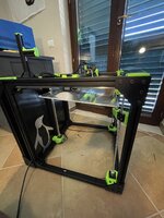
It took a few weeks to get here, but I am 95% if the way through mechanical assembly of the RatRig Vcore 3. Expensive, but I think it will be worth it. It is a tank.

The kit was absolutely worth it. There are a ton of fiddly little pieces and screws. Everything came cut, and the screws were all bagged and labeled.

Instructions for the frame were top notch. I am a little disappointed in the instructions for the extruded though. The official instructions are out of date, and there are a lot of options. Also a lot of little parts that require a specific order to make them work. Still think that it is going to be worth it.

So far I am probably 10 hours into assembly. I probably have another 5 to 10 to get the electronics assembled, installed, and tuned.

I can’t wait to be able to print 400x400 at 200mm/s.


52979f1e-117c-4669-90c3-055f92242515-jpeg.1672217
It has been months in the making but I finally got my first print off the ratrig


1998f872-60b8-4758-a232-a62a81bfef94-jpeg.1708839


Just your standard bench. Still have a fair amount of tuning to do. Lots of issue, probably compounded by the year old filament that has not been properly stored. However, this thing is the beast I expected it to be. 200 mm/s print speed and 3000 mm/s^2 acceleration is pretty darn cool. Certainly beats the 30 mm/s I am using on my Tevo Nereus.
 

Attachments

  • 1998F872-60B8-4758-A232-A62A81BFEF94.jpeg
    1998F872-60B8-4758-A232-A62A81BFEF94.jpeg
    479.6 KB · Views: 868

gte718p

Well-known member
Joined
Mar 12, 2009
Messages
3,950
Starting to calibrate. 40mmx40mm calibration cube 20 infill in just under an hour.


Step for x and y are almost perfect .07 mm large. I can live with that. Z was slight more of at .11 so I’ll adjust the e-steps. Got a lot of ringing on y. I may need to play with the belt tension.0AD584EC-39F9-4C60-AD41-2D2F0297A6B0.jpeg
 

littlemaster

New member
Joined
Aug 25, 2022
Messages
1
I was looking for a way to sharpen drill bits. Doing it by hand I was never convinced I got all the angles correct and I would end up chipping the leading corner of the cutting edge, or not give enough chisel angle so it cut too slow, etc.

Since I already had the adjustable backstop for my Bosch belt sander I used it as the base of operations. I can set up a 9° or 12° back angle which seemed common for the materials I drill and also a 118° and 135° side angle which are also common. The jig can slide side to side on the backstop to hit different parts of the belt, and helps make quick work of sharpening bits. I do need to make another one for smaller bits as they are a bit hard to hang on to with this.
I saw this tool and immediately thought about a jig for drilling holes at an angle. Is it possible to do something similar on a 3D printer and it won't be intellectual property theft? And will it be durable? It’s just that the KREG drilling jig has an iron bushing (if you can call it that), and I thought that because of this, the same fixture made on a 3D printer would not be very durable.
 
Last edited:

Outlander

Well-known member
Joined
Jul 30, 2010
Messages
5,154
Location
Quebec, Canada
I bought insulated screwdrivers for my basement workshop, now looking for storage solutions that elevate me from stuffing them in a drawer. It appears I am not the only Canadian Tire fanboy with a 3D printer.

https://www.canadiantire.ca/en/pdp/mastercraft-insulated-screwdriver-set-8-pc-0573695p.html?loc=plp
1661684529184.png
https://www.canadiantire.ca/en/pdp/mastercraft-insulated-precision-set-6-pc-0573604p.html?loc=plp
1661684561115.png

Yes, I got them on sale at the normal discounted prices !

I found these, but print times in Cura appear quite long so tweaking appears necessary.

https://www.thingiverse.com/thing:3320053
1661684676091.png

https://www.thingiverse.com/thing:3333983
1661684821830.png

I'll keep Googling screwdriver holders in the mean time, before I commit to day long prints.

No end of projects in the backlog!!
 

WoodsTruck

Well-known member
Joined
Jan 12, 2013
Messages
1,019
I saw this tool and immediately thought about a jig for drilling holes at an angle. Is it possible to do something similar on a 3D printer and it won't be intellectual property theft? And will it be durable? It’s just that the KREG drilling jig has an iron bushing (if you can call it that), and I thought that because of this, the same fixture made on a 3D printer would not be very durable.
I think you are correct that a centering bushing would need to be installed to keep the drill from forcing itself laterally when in use. After installing nutserts using heat, I wonder if a metal bushing on each end of the drill bit hole could be installed in the same manner. Print an undersized pocket for each and use a correct sized all-thread to pull the bushings into place so they are at least close to parallel when cured. IP gets copied all the time. I think you would find issue from KREG if you were trying to manufacture and benefit financially from your project, not just from a one-off in your shop.
 

no704

Well-known member
Joined
Apr 27, 2016
Messages
5,203
It has been months in the making but I finally got my first print off the ratrig


1998f872-60b8-4758-a232-a62a81bfef94-jpeg.1708839


Just your standard bench. Still have a fair amount of tuning to do. Lots of issue, probably compounded by the year old filament that has not been properly stored. However, this thing is the beast I expected it to be. 200 mm/s print speed and 3000 mm/s^2 acceleration is pretty darn cool. Certainly beats the 30 mm/s I am using on my Tevo Nereus.
Throw the filament in the oven 160f for a couple hours.
 
To avoid these ads, REGISTER NOW!

gte718p

Well-known member
Joined
Mar 12, 2009
Messages
3,950
Throw the filament in the oven 160f for a couple hours.
I would if I cared. The spool is almost done. I’ll live with the oozing.

I printed almost a full spool of 3DO petg, making a cooling fan duct for the printer, a pen holder for the desk, and a holder for the electronics pliers. Everything printed beautifully.
 

Jehannum

Well-known member
Joined
May 3, 2012
Messages
1,347
Location
Albuquerque, NM
I saw this tool and immediately thought about a jig for drilling holes at an angle. Is it possible to do something similar on a 3D printer and it won't be intellectual property theft? And will it be durable? It’s just that the KREG drilling jig has an iron bushing (if you can call it that), and I thought that because of this, the same fixture made on a 3D printer would not be very durable.
I made a couple of those to center a drill in a blind hole when I needed to drill a broken bolt out of on my Audi's slave cylinder mount.

IMG_20201005_163055729_HDR.jpg

IMG_20201005_163224709.jpg

It wasn't the most glorious or accurate thing in the world, but I did get a helicoil in there afterwards without too much drama.
 

Jehannum

Well-known member
Joined
May 3, 2012
Messages
1,347
Location
Albuquerque, NM
Some more progress. Hangers for ratchets, racks for pliers, and another rack for screwdrivers.
messages_0 (8).jpeg

Now I've _almost_ got a handle on the socket drawer. The orange things are from here: https://www.thingiverse.com/thing:4419966

I've got some 12x3mm magnets underneath to hold the extensions down, and they're held in place by clutch force between the socket trays and the sides of the drawer.

messages_0(4).jpeg
 

ER70S-2

Well-known member
Joined
Jan 2, 2015
Messages
796
I made a few quick cylinders out of PLA to use as temporary spacers for a project. I designed them in Fusion 360 to be 0.500" OD and 1.937" tall. When done, they measured exactly 1.937" long with digital calipers. How cool is that? I'm going to use it for all kinds of setup type of stuff.

Next, I need to adjust a pulley to be 71mm away from the motor's mounting surface. It's impossible to measure easily with normal measuring tools, so I'm going to print two 71mm cylinders and lay a straight edge across them.

Does anyone else use their printer for stuff like this?
 

Jehannum

Well-known member
Joined
May 3, 2012
Messages
1,347
Location
Albuquerque, NM
I made a few quick cylinders out of PLA to use as temporary spacers for a project. I designed them in Fusion 360 to be 0.500" OD and 1.937" tall. When done, they measured exactly 1.937" long with digital calipers. How cool is that? I'm going to use it for all kinds of setup type of stuff.

Next, I need to adjust a pulley to be 71mm away from the motor's mounting surface. It's impossible to measure easily with normal measuring tools, so I'm going to print two 71mm cylinders and lay a straight edge across them.

Does anyone else use their printer for stuff like this?
I made a parameterized wheel spacer to figure out how much of a spacer I needed to buy to clear the front brakes with the Enkei 92s on my 240Z.


I arrived at 5mm, which clears the brakes with a few mm to spare, but I printed 5 or 6 of them to arrive at that conclusion.
 

Grimpala

Well-known member
Joined
Jul 16, 2012
Messages
1,404
I made a few quick cylinders out of PLA to use as temporary spacers for a project. I designed them in Fusion 360 to be 0.500" OD and 1.937" tall. When done, they measured exactly 1.937" long with digital calipers. How cool is that? I'm going to use it for all kinds of setup type of stuff.

Next, I need to adjust a pulley to be 71mm away from the motor's mounting surface. It's impossible to measure easily with normal measuring tools, so I'm going to print two 71mm cylinders and lay a straight edge across them.

Does anyone else use their printer for stuff like this?

I made a parameterized wheel spacer to figure out how much of a spacer I needed to buy to clear the front brakes with the Enkei 92s on my 240Z.


I arrived at 5mm, which clears the brakes with a few mm to spare, but I printed 5 or 6 of them to arrive at that conclusion.
I had to put spacers on the rear of my Chevelle to achieve the desired back spacing of a particular set of wheels. The spacer was perfect, but the holes were made at ~5/8" and I have 1/2" wheel studs. Used the printer to make bushings to center the spacer on the studs. It is just shallower than the spacer and carries no load once the wheel is torqued. Kept the spacer from being offset and throwing off the balance.
 

Whiskeymike

Well-known member
Joined
Oct 31, 2013
Messages
775
Location
Austin, TX
Looking for a rabbit hole to dive down? Check out Gridfinity for storage management. Look in the video description for links to the files. They are all free from what I've seen.


Looks like I'll be spending the next few months printing boxes for my shop. I really like the modularity and use of magnets. Most of my surfaces are steel, so taking a box out of my tool cart and putting it on top of a table means it should be stable and not spill over too easily. My wife also wants me to print a few dozen of these for her sewing room. Might be a perfect opportunity to get a few more printers.
 

Poolshark314

Well-known member
Joined
Jul 5, 2021
Messages
658
Location
MD

Cruzan80

Well-known member
Joined
Jul 22, 2015
Messages
4,158
Location
Denver, CO
I think that is because of the opensource part. People are making/hosting in various places, as they choose. My guess (havent looked) is the original designer put his 150-ish in one spot, then everyone else piled in.
 

loganb

ALLIANCE MEMBER
Joined
Dec 29, 2011
Messages
5,494
Location
Omaha, NE
I've been working on a similar version but based on the grid setup from https://www.alch.shop/

Main difference vs the gridfinity is 42 vs 55mm grid and you have to pay for the full set I'm using. His initial revision of the grid and organizers is on thingiverse. I've now remodeled the small organizers bins to better fit how I'm using them, but am pretty happy with it.

20220908_213937.jpg

Attached is the first fastener drawer I've tackled with it. The shorter boxes on the left are stackable to the same height as the "full height" boxes. Still debating on if I use the same grid base for the toolbox or if I use magnets embedded in bases there.
 

Jehannum

Well-known member
Joined
May 3, 2012
Messages
1,347
Location
Albuquerque, NM
I'm getting ready to have my roof replaced on the 28th, and circumstances and schedules have dictated that I am doing the R&R on my solar PV array.

So, I made the MC4 key out of ABS to safely disconnect the connectors.

IMG_20220910_143413355.jpg

Hopefully I can safely disconnect them without breaking things. They've been up there since 2016, so I don't have a lot of hope, and will probably have to order some spare MC4 connectors.
 
OP
B

BoilermakerFan

Well-known member
Joined
Apr 17, 2006
Messages
2,188
Location
Indianapolis, Indiana
It's been a bit since I've been on GJ, but I did get my Prusa working again. All the bouncing from the move apparently pinched a couple wires at the one Z motor so the insulation was nicked and causing problems. I did a temporary electrical tape repair as I was planning to order a pair of new 320mm screw Z motors to get the full z height from my stretched Bear upgrade.

Then the receptacle in the WIC I was using as my hobby space stopped working. Many months past and about 6-8 weeks ago my wife suggested we move my hobby bench back into my office and swap around all the stuff between the closet off my office and the WIC off the bonus room. The closet off my office was storage. That took a couple weekends to finish. Around that time MatterHackers ran a clearance sale and I missed out on a couple As Is Ender 5+ models. But I noticed a CR10 V3 for well under $200 that said it had either a control board or display issue. The fine print stated they were including a replacement control board and display so I grabbed it. When I unpacked everything there were actually two boards in the box and a touchscreen display that's not compatible with the stock CR10 boards. So i swapped the CR10 control board. The second board will support the touchscreen display, but it's from an Ender so it only had one Z axis socket. That's an easy enough work around but the replacement CR10 board seemed to do the trick and the display was fine.

Until it wasn't. Shortly after homing and getting ready to level the bed, a Z motor started cogging very badly. Hmmm. I've experienced this before. Went to pull the suspect Z motor to replace it and one of the wires just came out of the motor connector. Yep, that easy. Used fine needle nose pliars to push it in. All good!

Time to start printing some upgrades for the CR10 on my Prusa... and then I discovered ExoSlides and their Creality upgrades. They only had XZ axis upgrades on the site so I emailed them about a Y axis upgrade. They took them off the site because there are so many variations of the CR10 family now. Ordered the full set of axis upgrades including the Z belt conversion. A shipping tune of parts arrived Thursday! I went with the Z belt conversion for a couple reasons, but the main one is that is only uses a single Z motor and a 90deg gear box. This changes the Z motor to be horizontal instead of vertical. This will be important to my future plans, but the single motor also allows me to swap over to the other Creality control board for now and use the touchscreen if I want to. The future plan for this printer is to move to the Duet system and utilize the Duet CAN expansion and closed loop driver boards! The LDO steppers for this system have encoders on the back of the motor, which is why the change to the Z axis and Z motor mount was important.

No pics to share yet. But after I get the ExoSlide conversion done I will post some up. I'm also trying to decide what extruder/hotend system I'm going to convert it over to. I have the Hemera mounting plate from ExoSlide already, but I may go with one of the MicroSwiss setups, especially if I can convert it to a Slice Engineering hotend. Also considering a BondTech/E3D REVO combo which will make part cooling easier than on the Hemera. E3D has a direct fit REVO hotend for the Creality family as well. That's the least expensive path by about $10 compared to the MicroSwiss direct drive system.

After the CR10 is completed, I am actually going to reduce the height of my Pruse bear MK2.5S back down to 220mm because I discovered it will fit on the middle shelf of my little cart I use to hold my printer(s). The CR10v3 will be on top with the control box and Prusa on the middle shelf. My tools and some filament will be on the bottom shelf. Eventually I'll put filament driers on the bottom shelf. The cart has a nice home in the closet off my office so I will finally setup my OctoPrint and some cams so I can run the printers with the closet door closed, but keep an eye on them through my Google Hub Max on my desk or my phone.
 
OP
B

BoilermakerFan

Well-known member
Joined
Apr 17, 2006
Messages
2,188
Location
Indianapolis, Indiana
I did a little more research into the Bondtech extruders, specifically the LGX. I discovered a small tidbit of info... The regular LGX will fit BMG mounts as long as the thickness of the plate is 3mm or less. My ExoSlide Hemera mount is 2mm thick. I can't see ExoSlide using a thicker plate for the BMG mount, but I emailed him to make sure.

MicroSwiss has a version of their direct drive extruder that comes with a ExoSlide mounting plate, but I'm not interested in the regular MS DD setup, I'm only interested in the MicroSwiss NG extruder. It's available in a Creality kit that includes the back plate to utilize the stock V-wheels, but not an ExoSlide version.

Here's a pic of the quantity of pieces involved in the full ExoSlide conversion (sitting on an 18gal Rubbermaid tote for reference):

IMG_2004.jpg
 
OP
B

BoilermakerFan

Well-known member
Joined
Apr 17, 2006
Messages
2,188
Location
Indianapolis, Indiana
Giles from ExoSlide confirmed the Bondtech bracket is 2mm thick! That means that either the BMG or LGX extruder will fit his bracket!

I haven't decided if I'll order the MicroSwiss NG to play with. We're not sure how compatible it will be with the ExoSlide Creality bracket due to it's unique setup. I know that worst case I could mod the NG stock back plate to attach it to the ExoSlide bracket, but if any holes have to be drilled or tapped, that will introduce a lot of potential for error or slight misalignment.
 

Jehannum

Well-known member
Joined
May 3, 2012
Messages
1,347
Location
Albuquerque, NM
Giles from ExoSlide confirmed the Bondtech bracket is 2mm thick! That means that either the BMG or LGX extruder will fit his bracket!

I haven't decided if I'll order the MicroSwiss NG to play with. We're not sure how compatible it will be with the ExoSlide Creality bracket due to it's unique setup. I know that worst case I could mod the NG stock back plate to attach it to the ExoSlide bracket, but if any holes have to be drilled or tapped, that will introduce a lot of potential for error or slight misalignment.
I'm interested in how you feel with it after the upgrade.

My CR-10's X gantry makes some odd noises at full tilt, which make me want to ditch the V-wheel setup. I had been leaning towards linear rails, but I hadn't seen these before.
 
OP
B

BoilermakerFan

Well-known member
Joined
Apr 17, 2006
Messages
2,188
Location
Indianapolis, Indiana
I'm interested in how you feel with it after the upgrade.

My CR-10's X gantry makes some odd noises at full tilt, which make me want to ditch the V-wheel setup. I had been leaning towards linear rails, but I hadn't seen these before.
Will do. I was looking at linear rails originally as well, but the full ExoSlide conversion was less expensive and will definitely improve the precision and durability over stock. High quality linear rails are great, but they need precise alignment or they will bind when running parallel rails. another advantage I saw in the ExoSlides was reduced weight on the X gantry. It might even reduce weight on the Y axis, but I'm not sure. Either way, it seemed like the best compromise to me for durability, consistency, precision, and cost.

I need to order the Bondtech mounting bracket from ExoSlide and Noctua fans... I'm considering a BTT board upgrade as well. Just because it's on sale right now and I can add the full color TFT WiFi screen that is a drop in replacement. The touchscreen I was sent will require modding the CR10 control box and it's not color, nor WiFi enabled.
 

Bessy

Well-known member
Joined
Dec 18, 2012
Messages
992
Location
Ontario, Canada
I did a little more research into the Bondtech extruders, specifically the LGX. I discovered a small tidbit of info... The regular LGX will fit BMG mounts as long as the thickness of the plate is 3mm or less. My ExoSlide Hemera mount is 2mm thick. I can't see ExoSlide using a thicker plate for the BMG mount, but I emailed him to make sure.

MicroSwiss has a version of their direct drive extruder that comes with a ExoSlide mounting plate, but I'm not interested in the regular MS DD setup, I'm only interested in the MicroSwiss NG extruder. It's available in a Creality kit that includes the back plate to utilize the stock V-wheels, but not an ExoSlide version.

Here's a pic of the quantity of pieces involved in the full ExoSlide conversion (sitting on an 18gal Rubbermaid tote for reference):

IMG_2004.jpg
Nerd!

Just kidding. Glad to see you back in the thread! I'm still a notch or two below novice so more than half of what you said went over my head, but I look forward to seeing your posts and subsequent builds!

Cheers!
 
To avoid these ads, REGISTER NOW!
Top Bottom