To avoid these ads, REGISTER NOW!

Above 1200 Sq/FT The Lone Beech Garage (60x46x16)

Wokspaces above 1200 squarefeet.
OP
S

sbosecker

Well-known member
Joined
Sep 25, 2012
Messages
3,539
Location
Peachtree City, GA
Re: The Lone Beech Garage Build Thread (60x46)

Continued...

I went to my basement where I keep my hardware cabinets. I didn't have washers that "worked". Either the outside diameter was too large or the inside diameter was too small.

I considered going to the hardware store but it was closed and I didn't know if I'd find a washer that worked there either. Maybe I could modify something I had on hand...


20180613-11.jpg

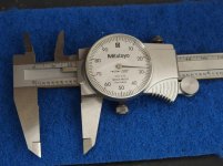
I decided that it would be easier to deal with making the outside diameter smaller than it would be to try to enlarge the hole in a washer. I measured the diameter of my available washer and it was .927". The 1956 washer was .860". I needed to reduce the radius of the washer by about 34 thousands of an inch.

So how to do that...


20180613-12.jpg

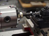
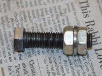
I found that a 1/2-inch bolt in my hardware cabinet fit the washer's inside diameter pretty closely. I put a nut on the bolt, then the washer and then another nut. I tightened the nuts against the washer and mounted it in my Mini-Lathe.


20180613-13.jpg 20180613-14.jpg

I reduced the diameter of the washer to the needed dimension.

I think it would almost certainly be easier to deburr the modified washer while it was still mounted on the bolt. Don't ask me how I learned this.


20180613-15.jpg

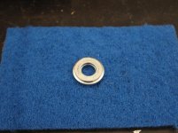
This picture shows a comparison of "before & after". The modified washer fits on the Tailstock perfectly and the Tailstock now functions correctly.


Scott
 
Last edited:
To avoid these ads, REGISTER NOW!

matt_i

Well-known member
Joined
Mar 14, 2008
Messages
10,753
Location
SE Michigan
Re: The Lone Beech Garage Build Thread (60x46)

Tuesday - June 12, 2018

Using a #22 drill bit, I drilled and tapped the hole for a #10-24 screw.
.

Maybe I'm doing it wrong but I've always used #25 for #10-24...I have a pack of 12 of the bits in my toolbox just for such occasions..:)
 
OP
S

sbosecker

Well-known member
Joined
Sep 25, 2012
Messages
3,539
Location
Peachtree City, GA
Maybe I'm doing it wrong but I've always used #25 for #10-24...I have a pack of 12 of the bits in my toolbox just for such occasions..:)

All my paperwork says #25 for #10-24. And I checked my tap cabinet... that drawer has #25s.

Gentlemen:

Thank you for your thoughtful posts...

I'm a firm believer in the concept: A little knowledge is a dangerous thing.

...so I very much appreciate you fellows weighing in on this.


20180615-01.jpg 20180615-02.jpg

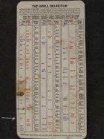
Inside the Tap & Die set I have is a piece of paper labeled: Tap-Drill Selector.

The Table has Red Tap Sizes (75% Thread) & Blue Tap Sizes (60% Thread). I have placed a black arrow pointing to the Red 10-24 Drill Size (#25) and a white arrow pointing to the Blue 10-24 Drill Size (#22).

The information at the top of the paper suggests a 60% thread for most applications as "these sizes provide 90% of the potential holding power." It goes on to suggest 75% for shallow holes in soft metal or mild steel.

As I have mentioned many times... I really don't know what I'm doing. I followed this guide to select the #22 Drill Bit for this task.

Speaking of "a little knowledge..."

I also have tapped the holes in my JET Mill dry. The information I found on the Interweb seemed to suggest dry tapping for cast iron. What do you guys think of that?


Best regards,

Scott
 
Last edited:

PelicanPines

ALLIANCE MEMBER
Joined
Apr 30, 2014
Messages
38,146
Location
New Jersey, USA, Earth, My own reality
To be honest... that's exactly what I thought you might be doing... I couldn't find my % chart... it shows what % you will get tap'd if you drilled with a certain drill. I got it from my FIL's machinist shop.

I bow to you tho… few do that because of the VOLUMN of the 75% charts out there.

Plus you changed the name of the thread... which brought me here.
 

matt_i

Well-known member
Joined
Mar 14, 2008
Messages
10,753
Location
SE Michigan
I just use the 75% chart for everything. Also, I think you are just fine tapping cast iron dry. I tapped some #4-40s last week into a CI ring, no lube, and all was just fine, threads look bright.

The lube seems to help get bright/smooth threads in mild steel and aluminum, otherwise there can be galling or tearing of the material. Typically I use Tap Magic for all materials.
 
OP
S

sbosecker

Well-known member
Joined
Sep 25, 2012
Messages
3,539
Location
Peachtree City, GA
To be honest... that's exactly what I thought you might be doing... I couldn't find my % chart... it shows what % you will get tap'd if you drilled with a certain drill. I got it from my FIL's machinist shop.

I bow to you tho… few do that because of the VOLUMN of the 75% charts out there.

Plus you changed the name of the thread... which brought me here.

I just use the 75% chart for everything. Also, I think you are just fine tapping cast iron dry. I tapped some #4-40s last week into a CI ring, no lube, and all was just fine, threads look bright.

The lube seems to help get bright/smooth threads in mild steel and aluminum, otherwise there can be galling or tearing of the material. Typically I use Tap Magic for all materials.


Gentlemen:

Thanks for the feedback! I just used the chart in the Tap & Die set because it was there.

Perhaps you guys can weigh in on something that is puzzling me which I will explain in detail in my next post.

As to the thread name change...
After the seemingly (to me) somewhat exasperated response from the moderator and then my posting of where I'd gotten the format for the title change, I thought he'd at least acknowledge I'd followed the directions posted by a different moderator... too much to ask I guess.


Best regards,

Scott
 
OP
S

sbosecker

Well-known member
Joined
Sep 25, 2012
Messages
3,539
Location
Peachtree City, GA
Saturday - June 23, 2018


About a week ago I was working on the JET Mill's Z-Axis Powerfeed. At that time I had completed the installation of the Limit Switch Bracket.
The two tasks that remained were the drilling of a 5mm hole into the shaft of the Powerfeed followed by inserting a spring pin into the hole.

I procured a set of metric drill bits earlier this week. Today I thought I had time to finish this project.


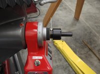
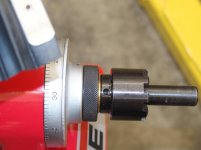
20180623-01.jpg

The 5mm hole needs to be drilled where the white arrow is pointing.


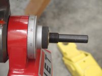
20180623-02.jpg 20180623-03.jpg

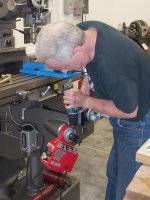
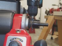
I was concerned about my ability to drill a hole freehand through the coupler. I thought it would be better to do this on the JET Mill and then use a hand drill to finish the job on the shaft. I was playing around with how to set this up when I heard a small voice whispering in my ear...

"Is it possible", the voice said, "that drilling through the coupler without it being on a shaft will gall the internal threads?"

This did seem like a reasonable concern and I could fix it (I thought) by inserting a bolt into the coupler during the drilling process.

Without thinking about it too much, I grabbed the coupler and went back to the house basement where my hardware cabinets are. I had some 3/4" bolts and some 1" bolts. The coupler fell somewhere in between. The largest metric bolt I had was 14mm - much to small.

Off to the local Hardware Store. The Hardware Store had 7/8"-9 bolts and that barely started to thread onto the coupler and then stopped. The largest metric bolt they had was 16mm. I was leaning towards this being a metric thread at this point and I was guessing at a size of 22mm.

A Tractor Supply store was close by and they tend to carry larger hardware but I didn't know if they were going to have metric in larger sizes. They had 20mm but no 22mm bolts.


20180623-04.jpg 20180623-05.jpg

I returned home and did what I should have done before I went on that wild goose chase. I measured the shaft's threads.

I got a surprise.

The metric thread gauges didn't really match. 2.0 pitch was close but didn't quite match.

SAE 12 matched exactly! I measured across the shaft's threads with a calipers and came up with .853"

7/8"-12?
22mm with not quite 2.0?

Two questions:

What thread am I dealing with here?

Do I need to be concerned about damaging the threads if I drill through the coupler without something threaded through the coupler?


Scott
 
Last edited:

shedfullatools

Well-known member
Joined
Apr 10, 2016
Messages
834
Location
Nova Scotia
I cant help with the thread size, however I will say that the chances of causing significant damage to the inside threads seem pretty minimal in this situation. Might be a slight burr to get past the first time its threaded together, once that breaks off its usually smooth sailing from there in my experience...
 
OP
S

sbosecker

Well-known member
Joined
Sep 25, 2012
Messages
3,539
Location
Peachtree City, GA
I cant help with the thread size, however I will say that the chances of causing significant damage to the inside threads seem pretty minimal in this situation. Might be a slight burr to get past the first time its threaded together, once that breaks off its usually smooth sailing from there in my experience...

ShedFullaTools,

Thanks! I'm still researching this. I may just get the hole started until close to the inside threads & then finish it on the shaft.

Best regards,

Scott
 
OP
S

sbosecker

Well-known member
Joined
Sep 25, 2012
Messages
3,539
Location
Peachtree City, GA
Monday - June 25, 2018

Various appointments kept me out of the shop today.

Maybe... just maybe... sometimes it might be better to be outside the shop than inside.


20180625-01.jpg 20180625-02.jpg

Just prior to sunset this evening a thunderstorm moved over the Lone Beech Garage and our house. After it passed, a magnificent double rainbow formed. By the time I grabbed my camera the rainbow had reduced itself to a - still impressive - single rainbow with just a shadow of the second.

Scott
 

drivesitfar

Well-known member
Joined
Oct 23, 2013
Messages
36,077
Location
Pacific Northwest
SB: i'm bumping up your thread and maybe another member can answer your questions on screw threads and sizing.

I thought i'd post a picture of a double rainbow I saw while sitting in a chair in a condo we rented on the Oregon Coast last January. on stormy days the waves actually spray water on the windows of this 2nd floor's unit.

since you travel all over the world have you been to the Oregon Coast in the past or lately? we actually like it more than Maui and it's about a 5 hour drive instead of a 5 hour plus plane ride.

keep up the great work in your awesome shop!!
 

Attachments

  • beach 3 (2).jpg
    beach 3 (2).jpg
    146 KB · Views: 44
  • cool chairs next to enclosed deck with radiant heated tile floor (2).jpg
    cool chairs next to enclosed deck with radiant heated tile floor (2).jpg
    149.1 KB · Views: 43
  • rainbow 1 (2).jpg
    rainbow 1 (2).jpg
    82.4 KB · Views: 47
OP
S

sbosecker

Well-known member
Joined
Sep 25, 2012
Messages
3,539
Location
Peachtree City, GA
SB: i'm bumping up your thread and maybe another member can answer your questions on screw threads and sizing.

I thought i'd post a picture of a double rainbow I saw while sitting in a chair in a condo we rented on the Oregon Coast last January. on stormy days the waves actually spray water on the windows of this 2nd floor's unit.

since you travel all over the world have you been to the Oregon Coast in the past or lately? we actually like it more than Maui and it's about a 5 hour drive instead of a 5 hour plus plane ride.

keep up the great work in your awesome shop!!


DrivesItFar,

Hawaii is the place for rainbows!

Actually the Oregon Coast was a spontaneous family trip we took back in 1998. An ancient forest in the sands off Neskowin, OR captured the public eye that year when winter storms scoured 10 feet of sand from the beach, revealing more than 200 stumps. This story was printed in a newspaper and I asked the family if they'd like to go see them.

I think we arrived, drove to Neskowin (high tide - really didn't see much in the way of stumps) drove north and spent quite a bit of time at the Tillamook Air Museum and eventually back to Portland for the night. Mt St Helens the next day and came back to Atlanta on the red-eye.

The kids were 10 & 8 and we had a great time!

Thanks for stopping by and for the kind words!

Best regards,

Scott
 
OP
S

sbosecker

Well-known member
Joined
Sep 25, 2012
Messages
3,539
Location
Peachtree City, GA
Wednesday - June 27, 2018


I had posted my concerns about drilling through the Z-Axis Powerfeed's threaded shaft here and on the Hobby-Machinist website. Generally speaking, there seemed to be concern in the responses that burrs might be an issue on the inside of the coupler.

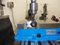
I decided to get on with the project. I modified my original plan of using the JET Mill to drill all the way through the coupler. I now would just drill through the top and use that hole to guide me as I used a hand drill to finish the job.


20180627-01.jpg

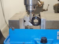
I used a edge-finder(.2") to locate the side of the coupler. I had already measured the coupler's diameter with a calipers and found it to be 1.180" in diameter.


20180627-02.jpg

After locating the edge of the coupler, I moved the table in .690" and drilled a 5mm hole into the top of the coupler.

I attempted to thread the coupler onto the Powerfeed shaft. It did not want to thread onto the shaft.

I removed the coupler and could see some burrs adjacent to the hole inside. I used a pick and cleaned the burrs out of the thread. I twisted a rag through the threaded hole a couple of times and tried mounting the coupler onto the Powerfeed shaft again.


20180627-03.jpg

It now threaded onto the shaft without issue.


20180627-04.jpg

Now it was time to attack the shaft with a hand held drill. I took my time and tried to keep the drill running true. I stopped and added cutting oil often.


20180627-05.jpg

After a bit of time the hole was completed.


20180627-06.jpg

I cleaned up hole and inserted the Spring Pin into the hole. I used Knipex Wrench Pliers to squeeze the pin into the 5mm hole. The parallel jaws of the Knipex did a nice job getting the pin most of the way into the hole.

Eventually - due to interference with the coupler - the Knipex's jaws were too big to seat the spring pin completely. I used a punch and a hammer to drive the pin the rest of the way into the hole.


20180627-07.jpg

A bit nerve racking drilling the hole freehand into the shaft but it turned out OK.

Except for tidying up some of the electrical wires, this completes the installation of the Z-Axis Powerfeed.


Scott
 
Last edited:

matt_i

Well-known member
Joined
Mar 14, 2008
Messages
10,753
Location
SE Michigan
Hi Scott

Checked back in today, glad you got thru the powerfeed issue. PM is always open if you ever need advice :)

That thread would seem to be a strange one, its possible its actually designed as a .860"-12. The difference between .875" and .856" would seem to be too large of a gap for 7/8" nominal.

One caution on drilling on the OD of anything as shown, it is an easy place for a drill bit to skate off the round surface and put a hole on a centerline different from the one carefully measured and aligned. For that I recommend "1/4" solid carbide spot drill 120 deg included angle". This is a short stubby drill bit which is solid carbide (~3x material rigidity of steel) and it won't skate. They are avaialable at McMaster or other edge tool supply houses. The rationale behind 120 deg included is that it pilots the 118 deg included "standard twist drill point" very reliably.

After putting the "spot" on the OD, then switch over to your nominal drill bit and it will follow the starting spot very well.

I've had to do a similar job mating new gears to distributor shafts, and in those I've had best luck fixturing both parts in the mill and using the edge finder on both as you did. Howeverrrrr :) the large housing of the powerfeed presents a unique challenge...I don't have a "top of the head" solution for that but would probably involve a V-block or other "bearing cap" 2-bolt fixture to try to grip the stub shaft. Many times if you can bore a hole ~.001"-.000" smaller than the shaft OD, cut it in half, apart with the bandsaw, and appropriate bolts, you can shop-make the fixture.

However, I think what you did is completely serviceable. The spring roll pins do a good job of handling misalignment up to a point.

Hammering roll pins is typical, in that case I'd try to cut a 2x4 (etc) as a backup column and place it between the floor and the shaft outboard end, then cut a small wood or metal wedge, tap that in gently at the floor level just to take up clearance (since the hand crank can't be used quite yet) and now you have more confidence the hammer blows won't bend the shaft. A good tool to add to your collection is a set of ball-pointed drive pins/punches specifically for these spring roll pins. The ball point self-centers the punch so there's no risk of scarring the hole as the pin is exiting. A flat punch can be used with care but a lot more risk of scarring the hole, especially if you get into someone else's work with poorly aligned holes, requiring heavier blows and bigger hammers.

Cheers!
 
OP
S

sbosecker

Well-known member
Joined
Sep 25, 2012
Messages
3,539
Location
Peachtree City, GA
Hi Scott

Checked back in today, glad you got thru the powerfeed issue. PM is always open if you ever need advice :)

That thread would seem to be a strange one, its possible its actually designed as a .860"-12. The difference between .875" and .856" would seem to be too large of a gap for 7/8" nominal.

One caution on drilling on the OD of anything as shown, it is an easy place for a drill bit to skate off the round surface and put a hole on a centerline different from the one carefully measured and aligned. For that I recommend "1/4" solid carbide spot drill 120 deg included angle". This is a short stubby drill bit which is solid carbide (~3x material rigidity of steel) and it won't skate. They are avaialable at McMaster or other edge tool supply houses. The rationale behind 120 deg included is that it pilots the 118 deg included "standard twist drill point" very reliably.

After putting the "spot" on the OD, then switch over to your nominal drill bit and it will follow the starting spot very well.

I've had to do a similar job mating new gears to distributor shafts, and in those I've had best luck fixturing both parts in the mill and using the edge finder on both as you did. Howeverrrrr :) the large housing of the powerfeed presents a unique challenge...I don't have a "top of the head" solution for that but would probably involve a V-block or other "bearing cap" 2-bolt fixture to try to grip the stub shaft. Many times if you can bore a hole ~.001"-.000" smaller than the shaft OD, cut it in half, apart with the bandsaw, and appropriate bolts, you can shop-make the fixture.

However, I think what you did is completely serviceable. The spring roll pins do a good job of handling misalignment up to a point.

Hammering roll pins is typical, in that case I'd try to cut a 2x4 (etc) as a backup column and place it between the floor and the shaft outboard end, then cut a small wood or metal wedge, tap that in gently at the floor level just to take up clearance (since the hand crank can't be used quite yet) and now you have more confidence the hammer blows won't bend the shaft. A good tool to add to your collection is a set of ball-pointed drive pins/punches specifically for these spring roll pins. The ball point self-centers the punch so there's no risk of scarring the hole as the pin is exiting. A flat punch can be used with care but a lot more risk of scarring the hole, especially if you get into someone else's work with poorly aligned holes, requiring heavier blows and bigger hammers.

Cheers!


matt_i,

Thank you for your very thoughtful post

...and the lifeline!


20180627-11.jpg

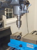
I don't have a spot drill so I used a center drill. Not the right tool but I did want my drill bit to have something other than a smooth rounded piece of steel to begin cutting on.

Thanks for the information regarding the Spot Drill. Any brands you favor?

I was looking at the installation instructions (instructions - Ha!) for the Y-Axis Powerfeed earlier this evening. They are sparse but I was startled to read that I may have to install another pin.

I thought I was done with that.

Best regards,

Scott
 
Last edited:
OP
S

sbosecker

Well-known member
Joined
Sep 25, 2012
Messages
3,539
Location
Peachtree City, GA
Friday - June 29, 2018


20180629-01.jpg 20180629-02.jpg

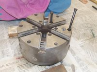
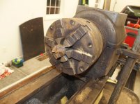
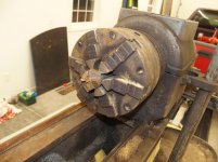
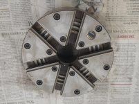
Back in January, I purchased a 1956 Delta-Rockwell 11-Inch Metal Lathe. Mounted on the headstock at that time was a 6-Jaw Chuck that apparently was being used to turn wood ...well, at least something different than metal.

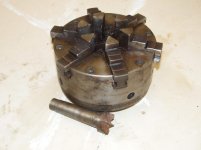
I removed some of the "patina" and discovered that this was a Model 3662 Adjust-Tru Buck Chuck. A reputable brand and, if I could get her cleaned up, a pretty nice chuck.


20180629-03.jpg 20180629-04.jpg 20180629-05.jpg

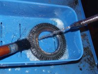
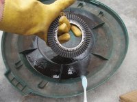
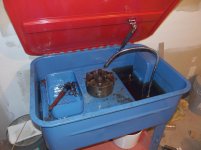
Yesterday I began the cleanup in earnest. I took the chuck to the Harbor Freight Parts Washer in the basement of my house and turned on the machine.


20180629-06.jpg 20180629-07.jpg

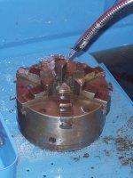
This morning I retrieved the chuck and its jaws from the Parts Washer. A bit of additional work was required but, once that was accomplished, the Chuck's exterior and the Jaws were cleaning up nicely.


Continued in next post...


Key Words: Buck Chuck 3662 6-Jaw Adjust-Tru Disassembly
 
Last edited:
OP
S

sbosecker

Well-known member
Joined
Sep 25, 2012
Messages
3,539
Location
Peachtree City, GA
Continued...


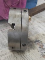
Now I needed to take the chuck apart to be able to clean its innards.


20180629-11.jpg 20180629-12.jpg

I looked for witness marks but found none. I got a punch and put a series of miniature craters on the chuck. This should ensure that I goes back together the way it came apart.


20180629-13.jpg

The first order of business was to loosen the 4 "Adjust-Tru" screws.


20180629-14.jpg

Then I removed the 12 cap screws from the top of the Chuck.


20180629-15.jpg

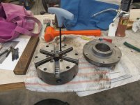
With the perimeter cap screws removed, the back plate pretty much fell off. Metal chips and sawdust were found inside.


20180629-16.jpg

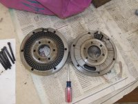
I thought separating the "middle" part of the chuck might be a chore. I got lucky and it started coming apart from the "upper" part of the chuck with just a little elbow grease.


20180629-17.jpg

Once I had a decent crack around the perimeter of the chuck, I used a couple of small screwdrivers as wedges to persuade the chuck to come apart. Not much effort was required to do this.


Continued in next post...
 
Last edited:
To avoid these ads, REGISTER NOW!
OP
S

sbosecker

Well-known member
Joined
Sep 25, 2012
Messages
3,539
Location
Peachtree City, GA
Continued...


20180629-21.jpg

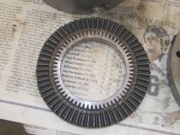
With the Chuck apart, I tried to remove the Scroll. I tapped the Chuck on the table a couple of times to try to get the Scroll to drop out but it didn't want to come out. I got a small piece of wood and tapped the Scroll around the perimeter of the Chuck.


20180629-22.jpg 20180629-23.jpg

Out she came!


20180629-24.jpg 20180629-25.jpg

These parts were given a shower in the Parts Washer as I went to bed this evening.

I have a social event that will preclude additional work on the Chuck until probably Sunday afternoon. I hope to reassemble the Chuck then.


Scott
 
Last edited:
OP
S

sbosecker

Well-known member
Joined
Sep 25, 2012
Messages
3,539
Location
Peachtree City, GA
Sunday - July 1, 2018


After spending time in the Parts Washer the Chuck parts had a bit of residue on them after they dried. Maybe it's time to put fresh fluid in the Parts Washer.


20180701-01.jpg 20180701-02.jpg

Due to the residue, I thought it might be useful to give the Chuck components a hit of Brake Cleaner before reassembling the Chuck.


20180701-03.jpg 20180701-04.jpg

After the Brake Cleaner had dried it was time for lubrication and assembly. I followed the suggestions of Tubalcain on YouTube and I put drops of Mobile DTE 24 oil on surfaces that contacted other surfaces and rubbed it around with my fingers. I also put a bit of grease on the pinion.


20180701-05.jpg 20180701-06.jpg

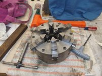
Light lubrication on the parts that slide together was essential for the Chuck's reassembly. The two small screwdrivers were used to keep the separated parts aligned as they were brought together. When everything was lined up the Cap Screws were tightened down.


20180701-07.jpg

Each Jaw's contact surfaces were lightly oiled


Continued in next post...
 
Last edited:
OP
S

sbosecker

Well-known member
Joined
Sep 25, 2012
Messages
3,539
Location
Peachtree City, GA
Continued...


20180701-11.jpg 20180701-12.jpg

Installation of the Jaws was next.


20180701-13.jpg

The final part of the assembly was tightening the Adjust-Tru mechanism. I tried to tighten the adjusting screws equally all the way around the Chuck. If I were ready to use the Chuck, additional fussing with these screws with the Chuck mounted on the lathe would be necessary.


20180629-01.jpg 20180701-14.jpg

Before & after: I think she looks better ...and she certainly operates more smoothly!


Scott
 
Last edited:
drivesitfar

Well-known member
Joined
Oct 23, 2013
Messages
36,077
Location
Pacific Northwest
SB: it looks like that was a pretty big job taking that Chuck apart and re assembling it, but since you use it every time (I think you do) you turn on the lathe i'm sure your benefits will be magnified many many times.

nice work and keep up the great posts and work in your cool shop/garage.

cheers
 
OP
S

sbosecker

Well-known member
Joined
Sep 25, 2012
Messages
3,539
Location
Peachtree City, GA
SB: it looks like that was a pretty big job taking that Chuck apart and re assembling it, but since you use it every time (I think you do) you turn on the lathe i'm sure your benefits will be magnified many many times.

nice work and keep up the great posts and work in your cool shop/garage.

cheers

DrivesItFar,

Thanks for stopping by and the kind words!

It wasn't too bad of a job thanks to folks who have documented similar refurbishments on YouTube.

I am amazed at how "Life" is keeping me out of the Lone Beech Garage here lately. Worse, looking at my calendar, it appears that various "events" are filling pretty much all free time until late October.

Unbelievable. Ha!

Best regards,

Scott
 
OP
S

sbosecker

Well-known member
Joined
Sep 25, 2012
Messages
3,539
Location
Peachtree City, GA
Friday - July 13, 2018

As I mentioned in my post to DrivesItFar, time in the shop seem to be at a premium this summer.

I did find a little time to address a repair issue on my wife's car today.


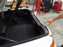
20180713-01.jpg 20180713-02.jpg

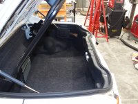
Some time ago the trunk lock on my wife's 1997 Honda del Sol failed. The trunk will lock but rotating the key in the trunk's lock cylinder will not unlock the trunk.

A review of Interweb seemed to point to a plastic clip that connects a rod from the trunk lock to the actual trunk latch mechanism. This seemed like a likely suspect but I thought it better to confirm this before ordering the part.

With that in mind on this hot July day in Georgia, I drove the del Sol into the Lone Beech Garage's (cool) Auto Service Bay and started to work.


20180713-03.jpg 20180713-04.jpg 20180713-05.jpg

The first order of business is to remove the cover of a separate latch. This latch controls a storage rack for the del Sol's Targa Top. The storage rack allows the Targa Top to be removed and stored in the trunk. The storage rack can be locked down via this latch or unlocked and swung up to allow access to the storage area of the trunk even with the Targa Top secured to the rack.


20180713-06.jpg

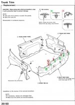
At this point a review of the location of various clips holding the inner rear trunk trim in place is in order.

There are 4 visible Square Topped Clips (shaded red) holding the trim to the frame as well as several hidden "stab clips" (shaded green).


Continued in next post...

KEYWORDS: Honda del Sol Trunk Latch Clips
 
Last edited:
OP
S

sbosecker

Well-known member
Joined
Sep 25, 2012
Messages
3,539
Location
Peachtree City, GA
Continued...

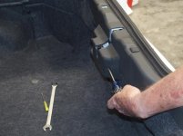
There is a YouTube video where a fellow mentioned a technique for removing these Square Headed Clips but he had already removed them when he posted the video. I decided to make a video showing the removal of a Square Headed Clip.

Click HERE to see that video.

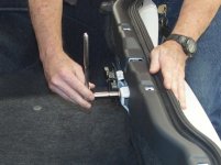
As I mentioned in my comments for this YouTube video, please forgive my bruised hand. A 9/16" Tappet Wrench was the perfect tool to twist the clip 90 degrees once the edge of the clip was lifted a bit. If one doesn't have a Tappet Wrench, a cheap Flea Market 9/16" Open End Wrench ground down to a thinner profile would work just as well.


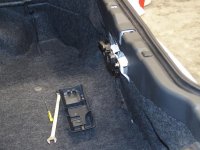
20180713-11.jpg 20180713-12.jpg 20180713-13.jpg

With the Square Headed Clips removed, judicious use of a Trim Removal Tool freed the hidden clips from the del Sol's frame. This last picture shows a couple of those hidden clips (white arrows).


20180713-14.jpg

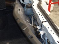
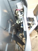
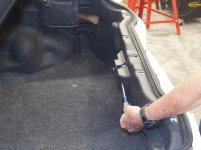
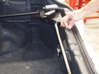
With the trim out of the way, the Rod (white arrow) that goes from the Trunk Lock Cylinder to the Trunk Latch (black arrow) was visible.

It looks like the plastic clip that attaches the Rod to the Trunk Latch has indeed failed. I ordered a new one from a local Honda dealer today. It should arrive by late next week.


Scott


KEYWORDS: Honda del Sol Trunk Latch Clips
 
Last edited:
OP
S

sbosecker

Well-known member
Joined
Sep 25, 2012
Messages
3,539
Location
Peachtree City, GA
Monday - July 23, 2018

As mentioned in my last post, between social & professional obligations shop time has been hard to come by. This past weekend I had a couple of simulators that kept me head down in my books pretty much the entire week leading up them. Today, with that parade of horribles in my rear view mirror, I was finally able to get back into the shop again after a long hiatus.


20180719-01.jpg 20180719-02.jpg

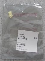
I had taken about an hour off from the study grind midweek to pick up a Honda del Sol Tailgate Lock Snap from a Honda Dealership in Newnan, GA. I resisted the temptation to attempt the repair until my simulators were complete.


20180723-03.jpg

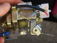
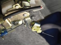
So today I got to it! Here's a picture of the latch with an arrow pointing to the broken clip.


20180723-04.jpg

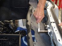
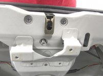
First of today's tasks was to remove the Targa Top Rack Latch. This has to be removed to allow unfettered access to the 3 screws that secure the Trunk Latch to the frame of the car.


20180723-05.jpg 20180723-06.jpg

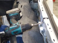
Here's where the wheels came off (a little). Those 3 screws had not been moved since 1997 and 2 of the 3 were not in the mood to leave their happy home. I tried a screwdriver initially and then an impact tool but all I did was chew up the screws without budging the two top ones.


20180723-07.jpg

At this point the only thing I had in my bag of tricks was some cheap Harbor Freight Left-Hand Twist drill bits. I drilled small holes at first without any positive results. I jumped up to the largest size in the set and that did the trick. The bit got enough torque on the two remaining screws to break them free.


Continued in next post...


KEYWORDS: Honda del Sol Trunk Latch
 
Last edited:
OP
S

sbosecker

Well-known member
Joined
Sep 25, 2012
Messages
3,539
Location
Peachtree City, GA
Continued...


20180723-11.jpg 20180723-12.jpg 20180723-13.jpg

The first picture shows the Trunk Latch with the broken clip.
The second pictures shows the broken clip next to the new clip.
The last pictures shows the Trunk Latch with the new clip installed.


20180723-14.jpg

I was pleased that I was able to attach the rod that goes to the lock without having to remove it from the lock assembly. There was enough "slop" in this arrangement to attach the rod to the Trunk Latch without too much trouble.


20180723-15.jpg

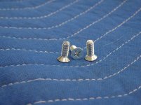
I ran to a local hardware store and got 3 M6-1.0 16mm screws.


20180723-16.jpg

I got the trim's hidden clips seated back in the frame.


20180723-17.jpg

Now it was time to install the Targa Top Storage Rack Latch.


Continued in next post...


KEYWORDS: Honda del Sol Trunk Latch
 
Last edited:
OP
S

sbosecker

Well-known member
Joined
Sep 25, 2012
Messages
3,539
Location
Peachtree City, GA
Continued...


After I fastened the Roof Rack Latch, I tried to engage the Rack into the Latch. The Latch would not "grab" the rack.

This was an issue I feared would happen with the Trunk Latch after it was removed and reinstalled. I had made some "Witness Marks" with a pencil to help relocate the Trunk Latch when I reinstalled it. That latch went into position without issue. I was very pleased with that as I was concerned the Trunk Latch might lock and then be out of alignment enough to keep the Trunk from opening.

Not being able to open the Trunk would have been a bad thing.


20180723-21.jpg

I loosened the two bolts holding the Roof Rack Latch to the frame. I lined up the Roof Rack Latch with the Roof Rack and tightened the bolts.


20180723-22.jpg

I installed the Roof Rack Latch Trim.


20180723-23.jpg

The Square Trim Clips that were a bit of a challenge to remove snapped into place amazingly easily.


20180723-24.jpg

Job done!
I was surprised how happy my wife was when I told her I had fixed the trunk lock. Apparently she often found opening the trunk via the handle next to the driver's seat a nuisance. I can see her point but I didn't realize it was bothering her that much or I may have addressed the problem earlier.


20180723-25.jpg

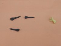
Now a small mystery. These 3 little black rubber "bits" were laying in the trunk after I pulled out the trim. I don't know if they are there from something I did during this procedure or if they are the result of something done prior to us taking ownership of the car 11 years ago. The old broken clip gives a little perspective on the size of these rubber items.


Scott


KEYWORDS: Honda del Sol Trunk Latch
 
Last edited:
OP
S

sbosecker

Well-known member
Joined
Sep 25, 2012
Messages
3,539
Location
Peachtree City, GA
Wednesday - July 25, 2018


Routine maintenance in the shop...


20180724-01.jpg 20180724-02.jpg

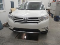
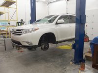
Yesterday afternoon I brought our 2013 Toyota Highlander into position over the "Tornado Shelter" to do a 40,000 mile oil change. The Highlander uses a cartridge oil filter which is pretty much a messy pain vs. the canister type but what do you do.


20180725-03.jpg 20180725-04.jpg

I let the oil drain from the oil pan overnight then put in a bit over 6 quarts of new oil. Next I drove the car around to the 2-Post lift to rotate the tires.

After the maintenance was finished this morning my spouse took the Highlander and I haven't seen her since.


20180725-05.jpg

After a few household chores were dealt with, I returned to the LBG this afternoon. It had been a while since I had paid much attention to my herd of tractors. I decided to take G3112 out for a drive in the bright Georgia sun.

For those of you who may not have had the experience of hearing the mighty Continental N62 engine idling, I made a video of the tractor sitting in front of the Lone Beech Garage after I had driven it to the end of the cul-de-sac and back. That video may be viewed HERE.

Scott
 
Last edited:
OP
S

sbosecker

Well-known member
Joined
Sep 25, 2012
Messages
3,539
Location
Peachtree City, GA
Thursday - July 26, 2018


Today I decided to devote a bit of shop time to my tractor herd. Having gotten G3012 out for some exercise yesterday, I turned my attention to G20304.


20180726-01.jpg

This tractor was built in 1949 and spent most of its useful life cultivating melon fields in Gibson County, IN. Gibson County was the next county south of Knox County where I grew up.

At some point a fellow in Evansville, IN had purchased the tractor. In 2010 this owner advertised this tractor for sale. I really wasn't that interested in the tractor but I was interested in some of the attachments he had with the tractor. I arranged to meet the seller during one of my visits to my parent's place (the Lone Beech Melon Farm) about 45 miles north of Evansville.

I knew the seller had been advertising the tractor for a while with no luck selling it so I was hoping I could talk him into just selling the attachments I was interested in. We talked for a while and then I pitched him an offer for the 3 items I was interested in.

He countered with a price $100 above mine. I was good with his price but I thought I'd pretend to ponder his offer for a moment and then suggest splitting the $100 difference.

As I stood looking at the tractor, counting slowly to 60 without speaking, the seller suddenly said, "The least I can take for the tractor and everything is $---."

This was a dramatic reduction in the advertised price and I was mightily tempted but... I had already told the seller my wife would skin me if I brought another tractor home.

I replied, "Well I could do the price but I don't know how I'd get the tractor to my parent's house in Vincennes." Before I could move the conversation back to the attachments the seller quickly said, "Oh, I could deliver it."

So that settled it. Ha!
He delivered the tractor to my folks farm the next evening.

I acquired the corn planter now mounted on the tractor from a fellow in Sparta, IL.

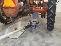
In the above picture the white arrow points to today's task. Installation of a new Battery Box.


20180726-02.jpg 20180726-03.jpg

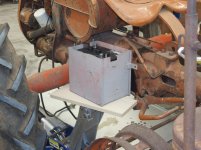
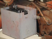
The old box is on the left and is actually in better shape than most of these almost 70 year old items. The bottom is facing the camera and three of the 4 remaining mounting tabs are on the left.

The replacement aftermarket box is on the right.


20180726-04.jpg

Arrows point to the brackets on the tractor to which the Battery Box will be fastened.


20180726-05.jpg 20180726-06.jpg 20180726-07.jpg

After I loaded a new battery into the new Battery Box, I used a floor jack to raise it into position.


Continued in next post...
 
Last edited:
OP
S

sbosecker

Well-known member
Joined
Sep 25, 2012
Messages
3,539
Location
Peachtree City, GA
Continued...


20180726-11.jpg 20180726-12.jpg

With the Battery Box in position, I fastened the box to the upper bracket.


20180726-13.jpg

Then I removed the floor jack and attached the remaining two bolts to the lower bracket.


I attached the two battery cables to the battery and prepared the tractor's engine to be started.

Once she was running, I took G20304 out for a drive. A video of me leaving the Lone Beech Garage on the tractor may be viewed by clicking HERE.


Scott
 
Last edited:
OP
S

sbosecker

Well-known member
Joined
Sep 25, 2012
Messages
3,539
Location
Peachtree City, GA
I have never heard a mighty Continental N62 before. That has a unique sound. I like it. Thanks for posting that.

ABSTIFFGS,

Ha!

It's even more distinctive due to a muffler that's pretty much shot and it's not running as smooth as it should be.

Thanks for stopping by!


Best regards,

Scott
 
OP
S

sbosecker

Well-known member
Joined
Sep 25, 2012
Messages
3,539
Location
Peachtree City, GA
Friday - July 27, 2018


Having had success in getting a different tractor started in each of the last two days, I decided to go for three in three days.


20180727-01.jpg

Meet G29253: Please don't hate her because she's beautiful. This tractor was my last acquisition and I thought I was tractored out before I got her.

However, back almost exactly 6 years ago I was perusing eBay and saw this tractor located in Geneva, AL. What made me decide to get this tractor was an unusual hydraulic setup that allows right hand and left hand moldboard plows to be mounted to this tractor at the same time.

One plow is used as one plows the field in one direction. Then the operator lifts that plow, turns around and drops the other plow and plows in the opposite direction.

Not only did this tractor have the split lift system for the two different plows but, even more unusual, the complete right hand and left hand plows came with the tractor! Usually these disappear as time goes by. These plows were not mounted on the tractor but were stored separate from the tractor. The tractor came with the Woods 42G Belly Mower that is currently attached to the tractor.

Despite her sketchy appearance, G29253 mechanically is arguably the most solid tractor I have.


20180727-02.jpg

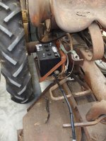
It is not unusual to find modifications that have been made to these machines over the years. Here is one that is actually quite useful. Somewhere along the line the original battery box was removed (probably because it had rusted out) and this more accessible platform was installed. Additionally a starter solenoid was added which allows the operator to reach down and touch a switch to start the tractor. The tractor's stock starting system requires the operator to pull a rod that runs to the starter through a hole in the right fender.

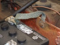
I intend to return to the stock starting setup at some point but, for now, I want to clean up the wiring that attaches to the battery. As one can see from the picture, the cable that goes to the battery's negative terminal is in bad shape.


20180727-03.jpg

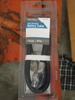
I dropped by a Tractor Supply store today and picked up an overly long replacement for the damaged cable.


20180727-04.jpg 20180727-05.jpg

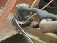
The old cable was removed from the solenoid.


20180727-06.jpg

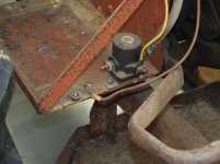
The new cable was attached to the solenoid and a new battery was installed. Despite the new cable, the starter wasn't really working very well.


20180727-07.jpg

I unfastened the bolt that attached the ground cable to the frame and gave all the contact points a good workover with some emery cloth.

What a difference! Now, despite some pretty old gas in the tank, G29253 started right up. These old 6 Volt electrical systems need all the help they can get!

A lot more work to do on these old girls but I hope to slowly bring them back - mechanically and in appearance - to what they were when they were new.


Scott
 
Last edited:

drivesitfar

Well-known member
Joined
Oct 23, 2013
Messages
36,077
Location
Pacific Northwest
SB: great work in the garage as per usual. :thumbup:

so I have to ask with all those tractors are you planning on doing a little farming outside the LONE BEECH GARAGE anytime soon?
 
OP
S

sbosecker

Well-known member
Joined
Sep 25, 2012
Messages
3,539
Location
Peachtree City, GA
SB: great work in the garage as per usual. :thumbup:

so I have to ask with all those tractors are you planning on doing a little farming outside the LONE BEECH GARAGE anytime soon?

DrivesItFar,

Been gone all week so sorry for the slow response...

No, I don't see me farming anytime in the next couple of years... and although I'll be retired then (2 years from now) I probably won't after that either.

...nor do I see myself - if I every acquire a '72 Chevelle SS - drag racing on some lonely road near some of Southern Indiana's river bottoms in the middle of the night.

Ha!

Best regards,

Scott
 

drivesitfar

Well-known member
Joined
Oct 23, 2013
Messages
36,077
Location
Pacific Northwest
SB: there is an advantage to growing your own food. we picked cherry tomatoes off our 3 little $1 plants and some basil off of our own plants and we bought some mozzarella cheese and dinner was served.

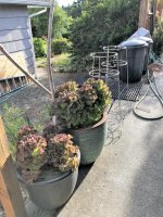
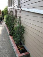
also these 7 little lettuce plants provided us with salad makings for almost 2 months eating maybe 2-3 salads a week. JUST SAYING that when you retire that grass you have might have another purpose, but you don't even really need that much space if you have some places that you can build some raised beds that get plenty of sunshine and/or shade depending on what you are growing. also a Fig tree or two might not be a bad idea.

that said it's kinda cool you have maybe more tractors than most farmers do, but I bet the new tractors almost run themselves with all the computer stuff on them.

RACE CAR?? do tell.

cheers and hope you are enjoying your weekend.
 

Attachments

  • fresh tomatoes, basil and lettuce 2.jpg
    fresh tomatoes, basil and lettuce 2.jpg
    143.8 KB · Views: 46
  • fresh tomatoes, basil and lettuce 3.jpg
    fresh tomatoes, basil and lettuce 3.jpg
    140 KB · Views: 44
  • fresh tomatoes, basil and lettuce 1.jpg
    fresh tomatoes, basil and lettuce 1.jpg
    144.7 KB · Views: 42
  • caprese salad sourdough bread and IPA.jpg
    caprese salad sourdough bread and IPA.jpg
    158.1 KB · Views: 38
  • cherry tomato harvest for the day.jpg
    cherry tomato harvest for the day.jpg
    137.6 KB · Views: 39
  • fig tree is packed with figs July 2018.jpg
    fig tree is packed with figs July 2018.jpg
    148.8 KB · Views: 44
  • Figs 2018 yummie.jpg
    Figs 2018 yummie.jpg
    97.2 KB · Views: 47
Last edited:
To avoid these ads, REGISTER NOW!
Top Bottom