To avoid these ads, REGISTER NOW!

Truss Design

OP
M

Medeek

Well-known member
Joined
Jan 13, 2013
Messages
550
Location
Copalis Beach, WA
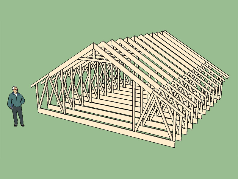
To further clarify the framing details with regards to attic trusses and structural outlookers I've created a sample model with a proposed dropped top chord gable end attic truss:
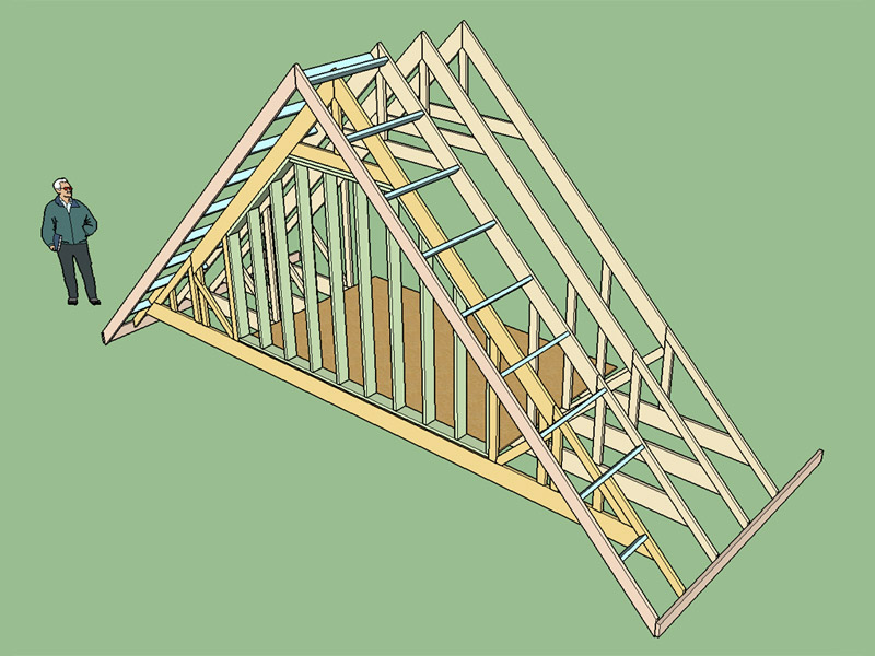
truss_su104_800.jpg


Please download and review the model here:

https://3dwarehouse.sketchup.com/model.html?id=u8c3afc5c-482a-41ea-b223-988b1cccd8bc

I've also included the infill wall framing to help put everything into reference (light green).

Is this the appropriate way to frame an attic truss (gable end) with structural outlookers?
 
To avoid these ads, REGISTER NOW!

larry4406

Well-known member
Joined
Jan 27, 2006
Messages
19,740
Location
Northern Virginia
..Is this the appropriate way to frame an attic truss (gable end) with structural outlookers?
I like your method of framing. Having the gable truss with a dropped chord and the "outlookers" framed into the 2nd truss makes the soffit very sturdy.

In the production houses my company builds this is never done however. Instead, the gable truss is the same profile as the other trusses which precludes this method. A ladder framed soffit is attached to the gable truss then the roof sheathing overhangs the roof and is nailed to the ladder.
 
OP
M

Medeek

Well-known member
Joined
Jan 13, 2013
Messages
550
Location
Copalis Beach, WA
I like your method of framing. Having the gable truss with a dropped chord and the "outlookers" framed into the 2nd truss makes the soffit very sturdy.

In the production houses my company builds this is never done however. Instead, the gable truss is the same profile as the other trusses which precludes this method. A ladder framed soffit is attached to the gable truss then the roof sheathing overhangs the roof and is nailed to the ladder.

That is what I have on a number of shop drawings for some previous jobs, the gable truss is essentially the same profile as the common trusses with the addition of some vert. members/webs for nailing off the sheathing. However, I am wondering if anyone has seen a gable end as I have shown with structural outlookers instead?
 
OP
M

Medeek

Well-known member
Joined
Jan 13, 2013
Messages
550
Location
Copalis Beach, WA
The reason I provide the full attic opening at the gable end truss is so that the framed in wall can be the nominal ext. wall thickness of 5.5 inches and allow for R-21 insulation. I've had some truss plants provide the typical vert. webs for nailing off the sheathing over this space but then one has to fir it all out anyways to get the appropriate wall thickness for the insulation.

If the wall below the gable end truss is sufficient for bearing then the gable end truss really does not need to have any structural capability so all of the diagonal webs can go away. One could also get away with a 2x4 dropped top chord with the stacked top chord at the eaves as shown. It would make sense to have the same depth at the bottom chord though so that the floor sheathing has a convenient nailing surface right to the edge of the building.

Alternatively one could do away with the gable end truss entirely and just balloon frame the wall from the ground floor up or from the attic floor up.

The question is which method should be employed within the plugin. I would prefer to use the most commonly employed solution.
 

Chris705

Well-known member
Joined
Nov 1, 2012
Messages
834
Location
The Finger Lakes of NY
I think there is not a "most commonly employed solution" As an architect I really like the way you detail the lookouts in your sketch up model (seems to be strongest to support wider overhangs and allows for fastening of soffit material directly to the members).
However most carpenters/framers would typically frame with the gable end wall rafter in line/plane with the top of trusses or other rafters if used. They would then use 2x material "on the flat" as lookouts to support the fascia board. Accomplished by using a skill saw to notch out the 1-1/2" thickness easily. If a gable end truss is used then they will typically use the ladder style soffit frame as was mentioned above.....
 
OP
M

Medeek

Well-known member
Joined
Jan 13, 2013
Messages
550
Location
Copalis Beach, WA
Six possible end details for a flat truss (Pratt 4 panels), there are probably others but these seem to be the most common:

truss_su105_800.jpg


1.) Mansard w/ Parapet
2.) Parapet
3.) Mansard
4.) Overhang
5.) Cantilever
6.) None

Both Mansard configurations can also have an optional overhang as shown. The Parapet configuration should allow for customizing the thickness of the parapet wall.

View model here:

https://3dwarehouse.sketchup.com/model.html?id=ude4e9b15-f67e-40de-a99f-97d2044182ad

This truss type with its many end configurations would work well with an HTML UI, that is the direction I will be going with future user inputs and interfaces since the ability to customize is unlimited.

With the flat trusses I will initially offer both Howe and Pratt with the ability to utilize a low slope or zero slope.
 
OP
M

Medeek

Well-known member
Joined
Jan 13, 2013
Messages
550
Location
Copalis Beach, WA
Version 1.4.8 - 04.01.2016
- Added Mod Fan common truss type.
- Structural outlookers (vert. & horz.) enabled under advanced roof options for Common (Mod Fan) truss type.

truss_su106_800.jpg


View model here:

https://3dwarehouse.sketchup.com/model.html?id=u3cf3d051-4d02-4490-af81-5693296cca33

With the addition of the Mod Fan (Triple Fan) the line up of common trusses is complete. I still need to add in raised heels and structural outlookers for some of the configurations.

Theoretically I could add in additional configurations of the Fink and Howe truss types for extremely large roofs but the largest I've ever seen is a raised heel Quad Fink (10/9). Large spans beyond 70'-80' are probably not practical as far as a single span common truss roof. At that point you pretty much go with large flat roofs with interior columns and girders and all steel construction (think Walmart or Cosco).
 

gsmith22

Well-known member
Joined
Jul 14, 2015
Messages
337
Location
Central NJ
I stumbled across this thread by accident. curious why you wouldn't have just used RISA to do the structural analysis instead of writing your own code. you can download for free a demo version that can have something like 50 members and joints. The geometry in RISA isn't fixed either - your truss can have whatever geometry you want it to be. To top it off, RISA will do checks against the NDS code for wood stresses. To some of your original questions, the special software used by the truss fabricators better get you the same answers as RISA. They are both based on physics. Probably the biggest discrepancies will center around how you decide to handle bending releases/fixity of members and end offsets where the members overlap in your model but don't in reality at connections. The truss fabricators have done tests to tell them how much their nail plates effect these conditions at the connections.

PS there is almost an infinite value to learning something like this. the lawyer that told you not to do it is the epitome of the problem with most of the US/world these days. Good for you.
 
OP
M

Medeek

Well-known member
Joined
Jan 13, 2013
Messages
550
Location
Copalis Beach, WA
I stumbled across this thread by accident. curious why you wouldn't have just used RISA to do the structural analysis instead of writing your own code. you can download for free a demo version that can have something like 50 members and joints. The geometry in RISA isn't fixed either - your truss can have whatever geometry you want it to be. To top it off, RISA will do checks against the NDS code for wood stresses. To some of your original questions, the special software used by the truss fabricators better get you the same answers as RISA. They are both based on physics. Probably the biggest discrepancies will center around how you decide to handle bending releases/fixity of members and end offsets where the members overlap in your model but don't in reality at connections. The truss fabricators have done tests to tell them how much their nail plates effect these conditions at the connections.

PS there is almost an infinite value to learning something like this. the lawyer that told you not to do it is the epitome of the problem with most of the US/world these days. Good for you.

I do use RISA quite commonly for analysis of specific jobs that I haven't written my own program for (which is pretty much everything except for the common fink truss.) I wrote my own matrix analysis program mostly for my own educational purposes and as an academic exercise and then used RISA to validate its results. It was a very satisfying feeling when the calculator was producing results (Moments, Shear, Axial) that were within 1% or less of RISA's output.

Another thing worth noting is that even though the TPI 1-2014 parallels very closely with the NDS and RISA there are some differences and thing peculiar to only trusses.

The problem with RISA is that it takes too long to setup the problem and the possibility for user error is too high for a technician or layperson. Hence, the truss plate manufacturers have devised their own programs that my program hopes to one day emulate.

Realistically I will probably never get there since I have neither the time nor the budget to produce a software that can compete against the big boys but at some point I will introduce plywood gusset plates which will make my software particularly suited for site built trusses in remote locations.

I have done considerable research and digging about trying to determine what is the best methods for handling the rigidity of the truss connections and how best to create the truss analog for modeling the truss. It is an interesting and complex problem.
 
Last edited:
OP
M

Medeek

Well-known member
Joined
Jan 13, 2013
Messages
550
Location
Copalis Beach, WA
Version 1.4.9 - 04.04.2016
- Added Tray truss type, configurations: (AUTO).
- Metric input enabled for tray truss type.
- Added gable end trusses for tray truss type.

truss_su108_800.jpg
 

gsmith22

Well-known member
Joined
Jul 14, 2015
Messages
337
Location
Central NJ
I hear you on RISA. You do have to know what you are doing.

From my own truss analysis experiences, I would keep chords as continuous members where they are in reality and provide a pin at chord splices (nail gang plate commonly 2 to 3' away from panel point). Pin all web members ends where they connect to chords. In reality, the nail plates transfer very little bending moment and even if they could, most web members are 2x4 and they can't transfer a lot of bending although your stiffness matrix should take care of that. And remember to do the end offsets on the web members to account for the shortened length where they overlap the chords.

The above really is only making minor shifts in load distribution/stresses - try it yourself. A fully pinned member truss will transfer everything in axial load. A fully fixed member truss will transfer a lot in axial and a good amount in bending. But the axial in the fixed model will be less to account for the increased bending. In the end, the interaction of stresses on the members will likely be similar for both models.

NDS is the code. TPI is specific stuff related to metal plate connected trusses but in the end, you have to meet the NDS in terms of limiting stresses on members and connections for compliance with the IBC/IRC. Good luck with your project.
 

7th Kahuna

Well-known member
Joined
Aug 4, 2012
Messages
1,704
Location
Los Angeles, CA
I haven't seen this thread in a while. I am really glad to see that you are still working on this and glad to see that you are having fun in the process.
 
OP
M

Medeek

Well-known member
Joined
Jan 13, 2013
Messages
550
Location
Copalis Beach, WA
Version 1.5.0 - 04.11.2016
- Added Mono Scissor truss type, configurations: (2/2, 3/3).
- Metric input enabled for mono scissor truss type.
- Added gable end trusses for mono scissor truss type.
- Structural outlookers (vert. & horz.) enabled under advanced roof options for Mono Scissor (2/2, 3/3) truss types.

truss_su110_800.jpg


When the raised heel option is selected the pitch of the bottom chord may equal the top chord creating a half vaulted parallel chord truss.

View model here:

https://3dwarehouse.sketchup.com/model.html?id=8e90b148-e241-4c88-b8b4-83c21ec12a3d

Raised heels are also enabled for this truss type, the combination of structural outlookers (vert & horz.) with the raised heel (wedge, slider, vert) makes for some interesting combinations and for some challenging logic/programming in order to get it all right.
 
Last edited:
OP
M

Medeek

Well-known member
Joined
Jan 13, 2013
Messages
550
Location
Copalis Beach, WA
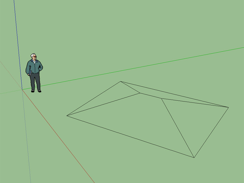
Updating the hip roof module so that an appropriate wireframe is displayed while using the roof positioning tool:

truss_su111_800.jpg


I will roll a revision once I've finished updating all of the rafter roof types with updated wireframes (preview graphics).
 
OP
M

Medeek

Well-known member
Joined
Jan 13, 2013
Messages
550
Location
Copalis Beach, WA
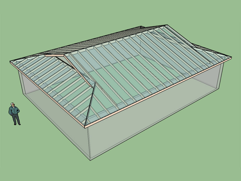
A nested dutch gable roof created with the plugin. The roof is initially generated by creating three dutch gable primitives and then deleting and trimming certain elements. The most time consuming is the creation of the two valley rafters. I think it might be helpful to have some sort of valley rafter tool if I can figure out a good way of doing that.

truss_su113_800.jpg


View model here:

https://3dwarehouse.sketchup.com/model.html?id=2676e970-a79e-40a3-8c77-63208c9d93ef
 

36truck

Well-known member
Joined
Jul 13, 2010
Messages
982
Location
UP of Michigan
I like your dropped gable end to allow outlooks to ride on top of the top cord. I've done that in the past. Works good for the snow load areas.
 
OP
M

Medeek

Well-known member
Joined
Jan 13, 2013
Messages
550
Location
Copalis Beach, WA
Per user request:

Version 1.5.2 - 04.18.2016
- Added energy/raised heels for small span attic trusses (less than 24 ft.), 1 variant: vertical w/ strut.
- Added some additional logic to improve the triangulation of the upper attic of attic trusses.

truss_su115_800.jpg


When I get some more time I will add in slider and wedge raised heel options for the attic truss type but at that moment it is low priority since most users seem to favor a fairly tall raised heel when utilizing it with attic trusses.
 
OP
M

Medeek

Well-known member
Joined
Jan 13, 2013
Messages
550
Location
Copalis Beach, WA
Version 1.5.3 - 04.20.2016
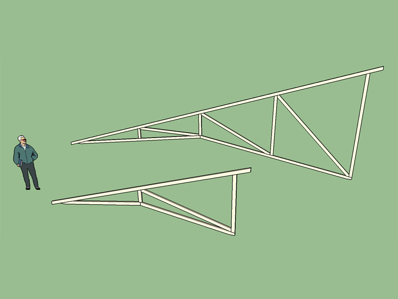
- Added Mono Cathedral truss type, configurations: (2/2, 4/4).
- Metric input enabled for mono cathedral truss type.
- Added gable end trusses for mono cathedral truss type.
- Structural outlookers (vert. & horz.) enabled under advanced roof options for Mono Cathedral (2/2, 4/4) truss types.
- Added Mono Scissor truss type, configuration: (4/4).

truss_su116_800.jpg


View model here:

https://3dwarehouse.sketchup.com/model.html?id=2ba29c11-a7b2-4913-a758-c005eb1288f9

I manually modeled this truss type about two months ago and I have been meaning to add it in, finally got it done tonight.

Manually created model here:

https://3dwarehouse.sketchup.com/model.html?id=u5c030ac2-f2e4-4c8d-8d9b-67bfa780ee7f
 
To avoid these ads, REGISTER NOW!
OP
M

Medeek

Well-known member
Joined
Jan 13, 2013
Messages
550
Location
Copalis Beach, WA
Version 1.5.4 - 04.21.2016
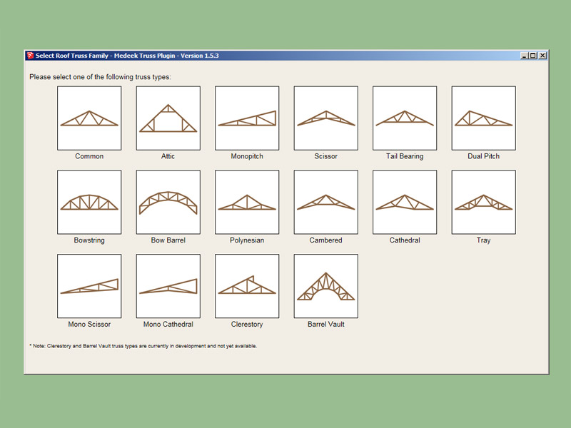
- Added a graphical user interface (GUI) for the selection of the truss type in the "Draw Roof Truss" sub-menu.
- GUI can be toggled with previous drop down menu within global settings.

truss_su118_800.jpg


truss_su117_800.jpg


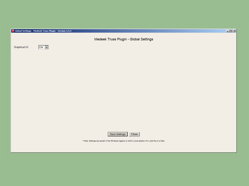
As you can see there is only one global setting at the moment but now that I have the interface and back end properly setup it won't take much to add in a number of other global values. At some point I will probably have enough parameters that I will need to enable some sort of tabbed html front end for the global setting menu.

With html web dialog boxes I am not sure how well they work on a Mac, the whole sync vs. async issue is a real problem for web dialogs and Macs. I only test on a PC so I can't guarantee 100% compatibility on a Mac. So far I haven't had too many complaints.
 
OP
M

Medeek

Well-known member
Joined
Jan 13, 2013
Messages
550
Location
Copalis Beach, WA
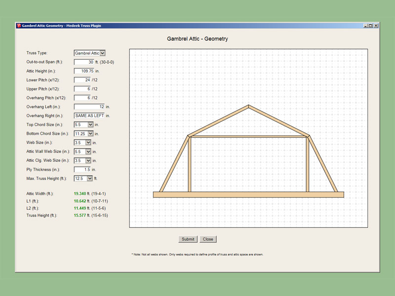
Here is a preview of the Geometry Input (GUI) menu for the upcoming gambrel attic truss.

truss_su119_800.jpg


Notice the preview pane which gives a basic profile of the truss and attic space. I still need to add some dimensions and some other symbols (pitch, bearing walls, etc...) to the preview graphics but it is mostly there and functioning quite admirably.

The GUI is html with javascript and SVG (scalable vector graphics) for the image. The nice thing is that changing any of the inputs will instantly update the dimensions and preview image allowing one to fine tune the truss geometry before proceeding further. For gambrel roofs this ability to adjust the proportions of the roof relative to each other is very important in my opinion. See my previous gambrel study here:

http://design.medeek.com/resources/truss/gambrelroofstudy.html
 
OP
M

Medeek

Well-known member
Joined
Jan 13, 2013
Messages
550
Location
Copalis Beach, WA
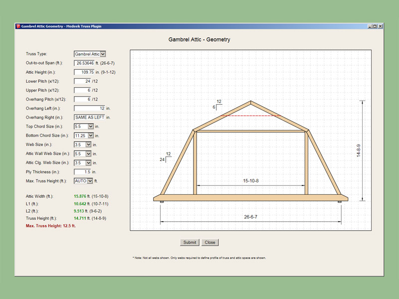
Updated screenshot of the gambrel attic menu:

truss_su120_800.jpg


This is getting pretty close to the final form that this menu will take.

It's actually really amazing what can be done with SVG and javascript, definitely not my forte but after this exercise I feel like I can probably construct anything with this combo if required.
 
OP
M

Medeek

Well-known member
Joined
Jan 13, 2013
Messages
550
Location
Copalis Beach, WA
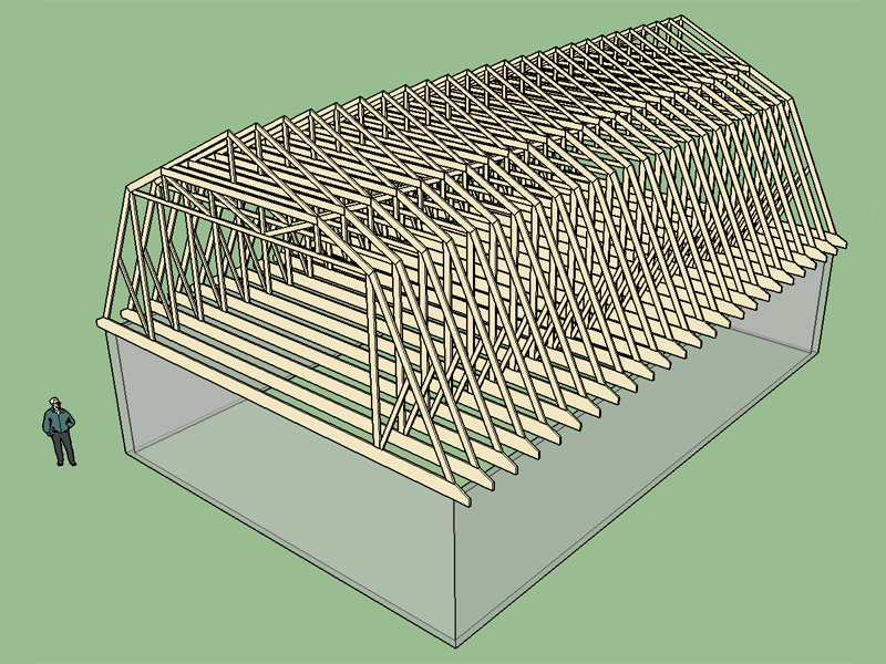
Version 1.5.5 - 04.29.2016
- Added Gambrel Attic truss type, configurations: (AUTO w/ piggyback trusses).
- Added a graphical user interface (GUI) for gambrel attic geometry input.

truss_su121_800.jpg


A reset button would be useful to return the GUI to the default values. There is still a lot of work to be done with the gambrel attic truss type:

- Advanced Options
- Gable Trusses
- Default or Reset Button
- Metric Input

View model here:

https://3dwarehouse.sketchup.com/model.html?id=fc8be11c-8bb1-4e60-a73e-5ba62628ae95
 

bczygan

Well-known member
Joined
Nov 4, 2009
Messages
22,002
Location
DETROIT! Arsenal of Scrappers
I haven't followed this thread closely, but think it's a great idea. Kudos to the OP!

A couple of questions.

Are there provisions in the programming to specify species of lumber?

And what about connections? Are there fastening methods that DIY people can use?

Bill
 
OP
M

Medeek

Well-known member
Joined
Jan 13, 2013
Messages
550
Location
Copalis Beach, WA
The plugin is integrated with the truss designer and beam calculator but it is very limited in its usage. I am working on adding in plywood gusset plates in lieu of metal plates but I am not there yet. There is also some potential liability issues with this so I am proceeding slowly.

The plugin is primarily an architect or designer tool with the focus on geometry. However, engineering will be a useful add-on.
 
OP
M

Medeek

Well-known member
Joined
Jan 13, 2013
Messages
550
Location
Copalis Beach, WA
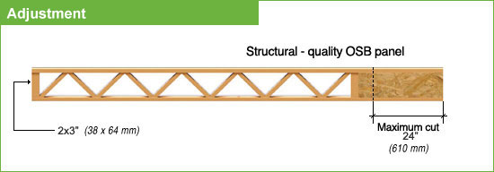
I am wondering how many of your designers/architects/contractors/builders out there have used Open Joist products?

http://www.openjoisttriforce.com/

I was thinking I might add their product line to the Floor Joist/Truss module.

prod-caract-ajust-img3-eng1.jpg


Quite a unique product in that it eliminates the plates with finger jointed webs and chords. In theory a stiffer truss than a typical MPC wood floor truss. Anyone have any experience with these.
 
OP
M

Medeek

Well-known member
Joined
Jan 13, 2013
Messages
550
Location
Copalis Beach, WA
For large agricultural buildings a double inverted truss can be employed to provide a large vaulted span for machinery:

double_inverted_large.jpg


I am wondering if this truss type is still commonly used by anyone for this type of application and whether it would be of interest, enough for me to add it into the growing list of trusses within the plugin.

Also if anyone has any shop drawings they could send me that would be very helpful.
 
OP
M

Medeek

Well-known member
Joined
Jan 13, 2013
Messages
550
Location
Copalis Beach, WA
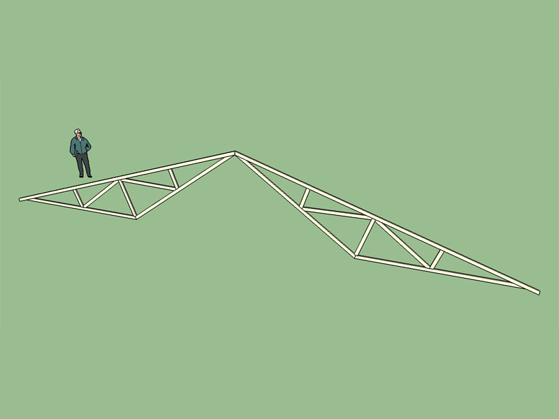
A quick study of a double inverted truss by taking two 24' howe trusses and joining them to form a double truss. Note that the 4:12 pitch of the original trusses is maintained and the interior vault is exactly 8:12 pitch.

truss_su122_800.jpg


View model here:

https://3dwarehouse.sketchup.com/model.html?id=d1f62979-cea5-42f0-97e4-16309098928a

My question with this configuration is how the top and bottom chords at the peak should **** up? For example should the bottom chords at the peak have a double scarf cut or a single scarf cut? Some shop drawings would help in determining what is common practice.
 
OP
M

Medeek

Well-known member
Joined
Jan 13, 2013
Messages
550
Location
Copalis Beach, WA
Version 1.5.7 - 05.15.2016
- Added Scissor truss type, configurations: (4/2, 6/4).
- Structural outlookers (vert. & horz.) enabled under advanced roof options for Scissor (4/2, 6/4) truss types.

truss_su123_800.jpg


View model here:

https://3dwarehouse.sketchup.com/model.html?id=620e816e-d809-4732-a19f-e425b4cc17fc

I also updated the pause in the truss selector GUI from 700 ms to 400 ms. Still more work to be done with raised heels and structural outlookers for some of these configurations but its getting close.
 
OP
M

Medeek

Well-known member
Joined
Jan 13, 2013
Messages
550
Location
Copalis Beach, WA
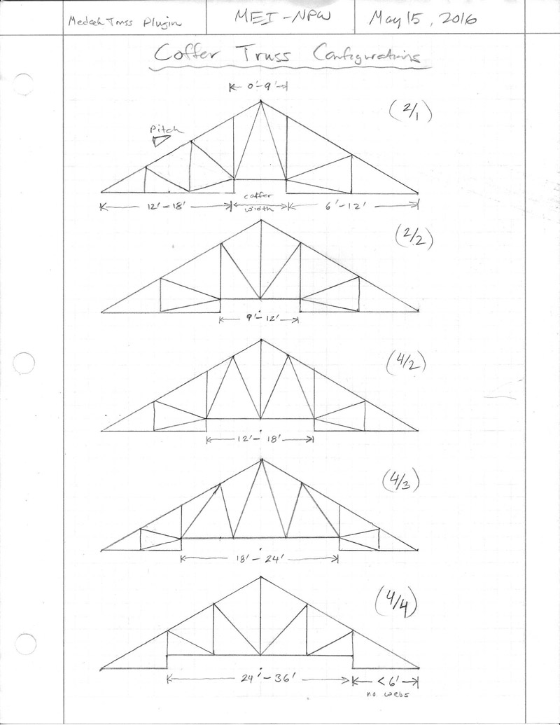
Coffer Truss Algorithm:

COFFER1_800.jpg


This is assuming that the coffer span is centered on the truss. A non-centered coffer algorithm could get significantly more interesting and difficult.
 
OP
M

Medeek

Well-known member
Joined
Jan 13, 2013
Messages
550
Location
Copalis Beach, WA
Version 1.5.8 - 05.22.2016
- Added metric input for Gambrel Attic truss type.
- Added a graphical user interface (GUI) for metric gambrel attic geometry input.

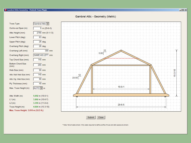
Gambrel Attic (metric) GUI

truss_su125_800.jpg


I also show the industry standard feet-inches-sixteenths.
 
OP
M

Medeek

Well-known member
Joined
Jan 13, 2013
Messages
550
Location
Copalis Beach, WA
Steep Scissor Trusses

Version 1.5.9 - 05.29.2016
- Increased top chord pitch limit from 12/12 to 18/12 for the following Scissor truss types, configurations: (2/2, 4/4).
- Heel web logic revised to accommodate steeper pitches for bottom and top chords of scissor trusses.
- Increased top chord pitch limit from 12/12 to 18/12 for valley truss sets.

16/12:12/12 Scissor Truss with an 18" raised heel:

truss_su126_800.jpg


Notice that the steep pitch of the bottom chord changes the way the heel web and bottom chord meet at the bearing point. The additional logic listed in the changelog notes deals specifically with this issue.

View model here:

https://3dwarehouse.sketchup.com/model.html?id=6c14d6c0-14c3-44cc-ba76-e4771fbfa936
 
OP
M

Medeek

Well-known member
Joined
Jan 13, 2013
Messages
550
Location
Copalis Beach, WA
Version 1.6.1 - 06.11.2016
- Added Coffer truss type, configurations: (AUTO).
- Metric input enabled for coffer truss type.
- Added gable end trusses for coffer truss type.
- Structural outlookers (vert. & horz.) enabled under advanced roof options for Coffer truss type.
- Building parameter menu (2nd) and advanced options menu for trusses now default to last picked options of the session for that sub-menu item.


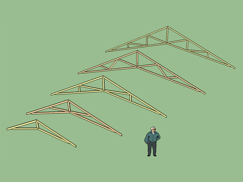
Various configurations of a 40' coffer truss shown below:

truss_su129_800.jpg


The web triangulation algorithm automatically determines which configuration is appropriate based on the span between panel points. This simplifies the geometry input menu but does take some control from the user.

View model here:

https://3dwarehouse.sketchup.com/model.html?id=a9f2e281-557d-4d13-a9ad-64bdfdd078f4
 
OP
M

Medeek

Well-known member
Joined
Jan 13, 2013
Messages
550
Location
Copalis Beach, WA
Version 1.6.2 - 06.14.2016
- Added Symmetric Cathedral truss type, configurations: (AUTO).
- Metric input enabled for symmetric cathedral truss type.
- Added gable end trusses for symmetric cathedral truss type.
- Structural outlookers (vert. & horz.) enabled under advanced roof options for Symmetric Cathedral truss type.

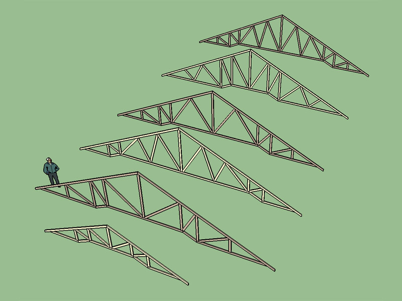
Various sizes and configurations of a symmetric cathedral truss:

truss_su130_800.jpg


View model here:

https://3dwarehouse.sketchup.com/model.html?id=2755897d-3855-447a-bc13-d4478cf99355
 
OP
M

Medeek

Well-known member
Joined
Jan 13, 2013
Messages
550
Location
Copalis Beach, WA
My trusses are 72" OC, but your Calculator only goes to 48". Are they special for that type of spread?

I'm going to assume that this is some sort of pole barn or post frame structure in which case you would usually double up two trusses per post. In that case you can analyze it as half your on center spacing since each truss has a tributary length of half the on center spacing. In this case I would use 36".
 
OP
M

Medeek

Well-known member
Joined
Jan 13, 2013
Messages
550
Location
Copalis Beach, WA
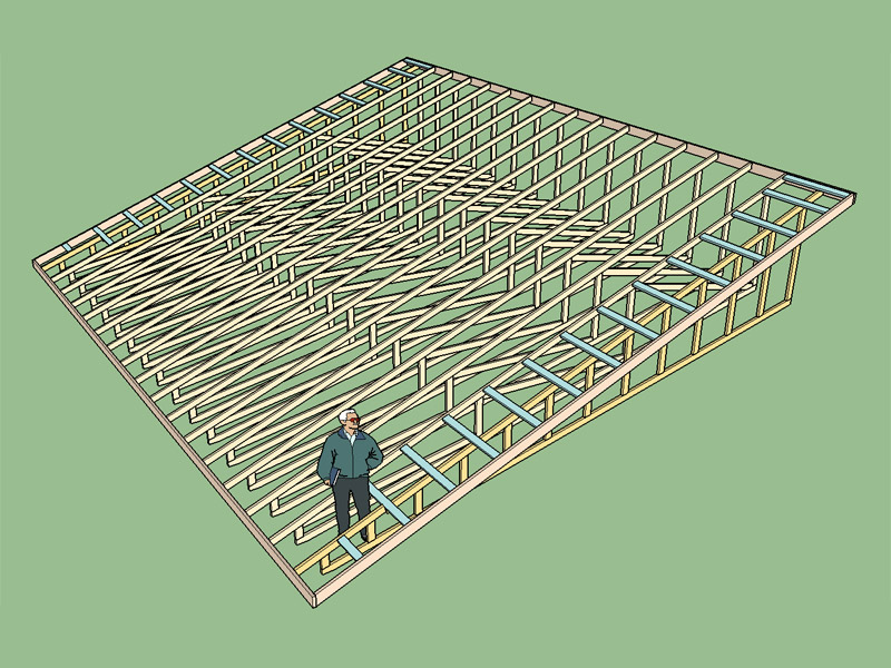
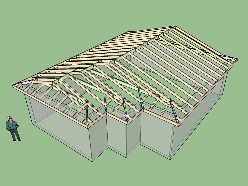
Modified an existing truss roof to make it a half hip truss set:

truss_su131_800.jpg


View model here:

https://3dwarehouse.sketchup.com/model.html?id=6e2633ca-ebb2-4597-87e9-ba41b47a636f

This will be my first venture into more complex truss systems. I figured I would cut my teeth on the half hip (Jerkin Head, Tudor Hip) truss set first before attacking the more complex full hip variants of which there are many.

After sketching this model up and examining the geometry I now have a number of questions:

1. Are my roof planes correct? Note that I have drawn the apex of the hip roofs at the edge of the last full truss and not at its centerline. Not entirely sure what is common practice in this regard.

2. I've shown some non-structural outlookers along the rake. What would the outlookers along the half hip portion look like?

3. If I use structural outlookers how would those be framed in over the hip section?

4. Does the apex of the half hip typically coincide with the next truss or could it land somewhere between trusses? ie. the half hip length is some multiple of the truss spacing.

5. Is the hip section usually the same pitch as the rest of the roof? There is really no reason why it has to be.

6. As the length of the half hip increases the depth of the gable end truss decreases as does the first inboard truss. What is the practical limit for the minimum depth of the first inboard truss?

7. Does anyone have some shop drawings of this type of truss set that I can study?
 
To avoid these ads, REGISTER NOW!
Top Bottom