bczygan
Well-known member
It's funny. A long time ago, in my work in an Architectural office, I did the same thing. Wondered if there was a program I could use to design trusses. Designing by hand was too time consuming. And modern high end houses have too many different conditions, so you are designing dozens of different ones for each house. So, while dissatisfied at the status-quo, I realized things were the way they were, for a reason. Actually, for a lot of reasons. When you get the program finished, I will play with it just for fun. It will be free on the net, right?
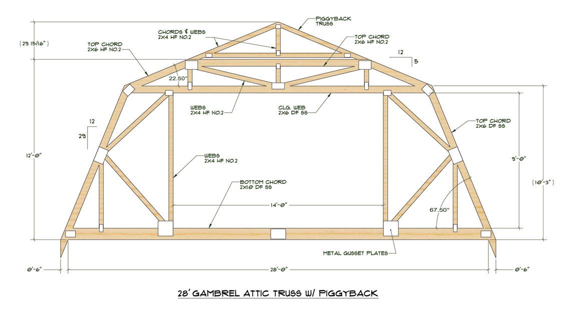
The one truss design I would like to see you address is the gambrel. It gives such volume, which for our shops and garages, with lifts, and the height restrictions on residential zoning, would be ideal. Also, if you can address rebuilding trusses in existing buildings, to provide additional height, that would be of value for the same reason.
I'd like to see a truss design calculator where the ceiling joists were raised and calculations done to reinforce the top chord between the raised joist and top plate.
Lots of conditions you could address that would be useful for us here.


")