To avoid these ads, REGISTER NOW!

Urethane: Materials and Methods

dladcock

Well-known member
Joined
Jan 29, 2010
Messages
855
Location
North Carolina
I had posted in the "What did you do in your garage" thread a couple of weeks ago. Post #7391 http://www.garagejournal.com/forum/showthread.php?p=3595889#post3595889 There was some interest in the process of using Castable Urethane, as promised, here's a walk-thru of the process and materials.


I'll add, to do this correctly, it's going to take more than one post. I'll do this post, then add-on until we've made the journey just to keep it all together.


I've been using castable Urethane materials for a bit over 10 years. It started as a want, later becoming a need. I had been researching methods and materials for a couple of years to fill a void in the supply of NOS and aftermarket rubber seals and the like for the Classic Car hobby.


Some of the applications I've encountered, are low production, with no hope of being reproduced by any of the major suppliers. Traditional method tooling costs alone for some of the parts I've reproduced can exceed $20,000. With that kind of overhead, the 3 major players in the U.S. restoration rubber and weather strip business just can't afford to invest that kind of money in tooling for low volume repop parts.


Now, NOS parts for Classics, are well........ you know what they are. Hard to find, very expensive and even if stored in the best of conditions, probably won't last once put into service. I mean, if you should replace a fan belt or radiator hose every 4 years, what can be expected of a 43 year old part?


The upper and lower shifter boots for 1968/69 Impalas (GM refers to them as "Seals") are very hard to come by NOS or used. I gave 500 bucks for this set. As a rule they sold around 1200.00 a set and up...... when you can find them. I might add that since these have become available the price of a NOS boot has dropped dramatically.


Here's one I made:

KGrHqIOKj4E5hZyZI6BOlzEYhYg60_57_zpsec1e0b45.jpg


And here is a cowl extension rubber for 1968-69 Impala, Caprice, Belair and Biscayne in the same foam type rubber as original.

KGrHqVpsE-zm-pQYBP7z4WJEw60_57_zpseaa230b4.jpg


So, that's the why.


The how is, done correctly, a longer story. The actual process is really not a difficult one. The materials are hazardous and just like anything else, deserve the same respect as painting or handling any chemicals. READ THE MSDS!!!


All the research I've done has been online. Just about anything you want to know regarding mold making and casting urethane is online...... then again, the stuff you can't find online you learn the hard way. I can help with that up to a point. I learn something new every part I cast. Each part is different in it's own way, it may have heavy under cuts, thick/thin sections, or cast-in inserts. Maybe they have any combination of all the above.


Some can be simple one-part molds and there are multi-part molds. I'll try to show what I've done with those as we go along.

The process also has another positive.... It's cost effective. I do have a tidy sum invested in equipment, although it's not prohibitive, I would have not purchased some of this equipment if this was a one-shot venture for me. I have something of a part-time mold shop going on here.


Some of the equipment you would need to do a one time project would include:

Electronic Gram Scale

Mold Forms

Glue Gun

Mold Release


A simple mold will consist of a containment field made from sulfur free clay, Masonite, Lexan or just about anything that will contain the liquid material until cured. I normally use Delrin and/or Lexan due to the fact that's what is easiest for me to access.


The mold form serves to hold the model in place and stable while the mold is being formed. I try to make the molds in two parts, simply because that's the easiest way to go. Some parts require multiple part molds and the complexity increases with every section that's added.

Here's the mold used for the 1969 Chevrolet clutch rod boot posted elsewhere:

IMG_0536_zps74bb4ade.jpg


And the reproduction boot:

IMG_0541_zps5ac97d24.jpg


So, this is the first installment. I'll leave a link to a preferred supplier who has a ton of information and videos showing their products in use.

http://www.smooth-on.com/

What ever the part may be I study the part and determine basically three things. Weight, Durometer and how I'll approach the mold configuration.

Weight is straight forward, simply weighing the part tells me how much material is required to cast the item. Most of the material I'm using is 1:1 and can be mixed by volume. However using an accurate gram scale helps maintain closer ratios and at the bottom of the bucket, there is no unused A or B component.

Durometer of the original part is critical if you're interested in reproducing an accurate representation of your part. I have Durometer Testers for both A and D Shore materials. "A" Shore material will be your softer, rubber type material and "D" Shore is for the harder, plastics. While not totally necessary, a tester will provide the best measurement of the hardness/softness of a given material.

As a rule, a rubber band is 25-30 Duro, a car tire is 55-60 Duro. Here's a chart the will give some insight regarding Durometer:

http://www.smooth-on.com/Durometer-Shore-Ha/c1370/index.html

Now, mold configuration is sort of a learned process and can take a fair amount of time to accomplish. It's two fold with a lot of preparation involved, but it's like painting..... You get what you put into it.

Look at almost any cast, injected molded part. Try to envision what the MOLD looks like, not the part. Try to see what's not there. That is what the mold looks like. The mold is a reverse of the part. At first, I had to look at parts a VERY long time to see the mold, now I can see it almost immediately unless it is a complex part.

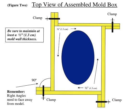
The simple part is the containment field or mold box. Here's a better description than I can give:
http://www.smooth-on.com/pages.php?pID=53&cID=11

Here is a tutorial that got my attention early on. The intricate detail in reproduction of a given part is unbelievable. This is also an example of a very simple project using the most basic techniques. Check it out.

http://www.smooth-on.com/gallery.php?galleryid=157

2-4-2014

Still Waiting for materials. In the meantime, here is the project so far. Doing a few things different than I have in the past, so if this turns to do-do, we'll all see it at the same time.

I made a leveling plate to rest the mold form on during the casting of the form. It's 12"x24"x3/4" Delrin with 4 3/8-24 socket head Allen bolts for leveling legs. All I'm shooting for here is a level surface that's easy to move around the shop. A couple of machinists levels and a couple of minutes, it's done.

IMG_0581_zps1e228ae1.jpg


IMG_0582_zps89bf105b.jpg


This is the part. Obsolete and very expensive when available from the original vendor. We could CNC this part out of Delrin, but there are some contours that are challenging. The bigger issue is that in Delrin, the fingers tend to snap off when put into a bind. 80-85 Durometer urethane is hard enough to maintain the shape and has enough flex to prevent breakage.

IMG_0583_zps79454508.jpg


IMG_0584_zpsb18bfec6.jpg


IMG_0585_zps1655dc2b.jpg


This is the inner structure of the mold form. It's purpose is to support the original part inside the containment field during the casting of the mold material. BTW, this time I'll be using a 30 Duro Silicone material. The mold material should be softer than the part or harder than the part to facilitate removal. If both sides (mold or part) are the same Durometer, it is difficult, if not impossible to remove the mold halves or part. You should be able to "peel" either the mold from the part or the part from the mold.

IMG_0586_zps44190ec2.jpg


IMG_0587_zps0e997072.jpg


Here's the part in place on the inner form.

IMG_0588_zps2c6d072b.jpg


IMG_0589_zpsc1548057.jpg


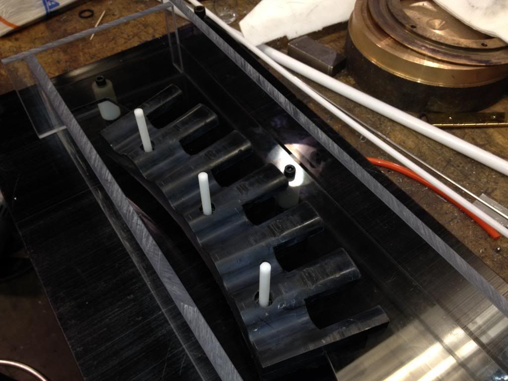
The part, inner form with the containment field walls.

IMG_0590_zpsca8205ab.jpg


IMG_0591_zps13d1d13c.jpg


Here the white Delrin pins will serve to form the holes for the mounting bolts. We could just drill these after the casting, but it will save that step later. Since these parts will be ongoing for some time to come, it's just smart to "mold in" as many machining steps as possible.

IMG_0592_zpsc52fdaf0.jpg


dla
 
Last edited:
To avoid these ads, REGISTER NOW!

TruckJunkie

Well-known member
Joined
Jun 3, 2010
Messages
144
Location
northern lower peninsula of MI
Thanks for starting this thread, I have been looking for some urethane tires for the idler wheels on a snowcat without much success. Have been thinking about trying to cast them myself, but did not know where to even begin looking as all the different formulations are very confusing.
 
OP
D

dladcock

Well-known member
Joined
Jan 29, 2010
Messages
855
Location
North Carolina
Thanks for starting this thread, I have been looking for some urethane tires for the idler wheels on a snowcat without much success. Have been thinking about trying to cast them myself, but did not know where to even begin looking as all the different formulations are very confusing.

Just curious here, what do these snowcat idler wheels look like, diameter, etc?

dla
 

A_Pmech

Well-known member
Joined
May 8, 2007
Messages
8,002
Location
IL
Good looking work dladcock.

I've made quite a bit of plastic tooling. I'd enjoy seeing how you go about making yours.
 
OP
D

dladcock

Well-known member
Joined
Jan 29, 2010
Messages
855
Location
North Carolina
What's your solution when you don't have a complete original or even a partial original to use to shape your molds?

Wes

You can build up a mold form from scratch if an original is non existent, of course it won't be an exact copy of an original. It can be as functional as an original part. If you have a partial, it is possible to repair the part to the point it can be used as an acceptable model. I've done repairs to boots, cast the mold, then worked out the unacceptable and undesirable flaws after the fact.

The idlers look like a 12" dia X 3' wide caster with
an aluminum wheel. I am on my phone currently or wouid attach a liink to a thread I atarted about them last summer.

Yes, do post the link. I'm always interested in seeing different projects, if only to broaden my perspective.

dla
 

Streetbu

Well-known member
Joined
Jan 7, 2014
Messages
3,082
Location
Central NY
Very interesting. Heard of a few people doing this for a small run of parts but I didn't know what was involved in the process. Keep'em coming!
 
OP
D

dladcock

Well-known member
Joined
Jan 29, 2010
Messages
855
Location
North Carolina
Very interesting. Heard of a few people doing this for a small run of parts but I didn't know what was involved in the process. Keep'em coming!

I'm currently working on a mold at work that will be utilized long term. It's an obsolete part and the mold will be semi-permanent. The part is one that will be needed on an ongoing basis. I'll be able to "rebuild" the mold as normal wear and tear occurs. The molds I've been doing for the boots are reusable, but when they wear out, that's it. They'll have to be recast. The life span depends on the care taken when using the molds and type of material used to construct them.

I'm documenting the work project with pictures so I can do an A to Z write up on the process. Material was ordered today and will take a couple of days to arrive. (usually, sometimes it takes forever:dunno:)
 

tc-cad

Well-known member
Joined
Jan 15, 2012
Messages
270
Location
Mequon, WI
This is the exact type of item that I think a 3-D scanning and 3-D printing business could thrive. I am very CAD/Design oriented and have some work with molding some check fixtures in my day job.

The original item could be scanned (potentially using a Kinect sensor) and then creating in CAD a upper and lower mold then 3-D printing the mold then you could pour as many as you could sell. I think there is a big future in 3-D scanning and 3-D printing.

TC-CAD
 
OP
D

dladcock

Well-known member
Joined
Jan 29, 2010
Messages
855
Location
North Carolina
So, I see I've exceeded the character limit. Here's the continuation from post #1.


Well, that's it for now. Next I'll walk through applying the mold release, sealing the containment field and securing the side walls of the box. Hopefully the material will be in and we can pour the lower half of the mold.
 
OP
D

dladcock

Well-known member
Joined
Jan 29, 2010
Messages
855
Location
North Carolina
Here is the link to my earlier thread about the urethane idler wheels - http://www.garagejournal.com/forum/showthread.php?t=203045&highlight=TruckJunkie

O.K. got it now.

How many idlers are required? Just the two in front or are there two more out back as well?

This wouldn't be a hard project to accomplish. I'd use the best condition idler to make measurements from and calculated the material required. You could either make a single mold to cast all the parts from or make 2-4 molds to cast all at one time.

Your mold construction options would be Smooth Cast 380, it's a hard tooling resin. Wood/MDF, a series of rings and flats or plastic, pvc in a similar configuration.

As for the actual tire material, I'd consider VytaFlex 60 urethane or maybe an epoxy if a harder material is needed. UV stabilizer can be added if there is the need for additional protection.
 
To avoid these ads, REGISTER NOW!

TruckJunkie

Well-known member
Joined
Jun 3, 2010
Messages
144
Location
northern lower peninsula of MI
Yes, there are just two idlers on the front, the remainder of the bogey wheels are pneumatic, though the sprockets on the rear also have cast urethane covers. From what I've gleaned so far, the tires need to be bonded to the rims, which are basically flat across the top, to keep them in place against the forces exerted by the track grousers. The one company who used to cast them advertised they used a 12 step method to bond them and they cast the tires directly to the rims. They also advertised their tires as being very UV resistant, which seems like a good idea because UV degradation is supposed to be the prime culprit which causes chunking of the tires as these had happen. I do have a small machine shop available to help make molds and/or forms as may be needed.
 

ChevyEFI

Well-known member
Joined
Sep 2, 2012
Messages
8,735
Location
Phoenix, AZ
They also advertised their tires as being very UV resistant, which seems like a good idea because UV degradation is supposed to be the prime culprit
if there is reading anyone could suggest for selecting an extremely UV resistant material for an automotive window, I'd appreciate it.
 
OP
D

dladcock

Well-known member
Joined
Jan 29, 2010
Messages
855
Location
North Carolina
So, I see I've exceeded the character limit. Here's the continuation from post #1.


Well, that's it for now. Next I'll walk through applying the mold release, sealing the containment field and securing the side walls of the box. Hopefully the material will be in and we can pour the lower half of the mold.

2-12-2014

Finally received the MOLD STAR 30 material to pour the mold halves for the sorter scallop. This material suits our needs in that it cures in 6 hours, and being silicone, will not require mold release. I'll still use some release, but normally silicone does not require release agent.

Here's the part in question just to refresh:

IMG_0592_zpsc52fdaf0.jpg


Today I started with turning a couple of sprues to pour the urethane material into and one that serves as a vent. Venting is required on most parts to allow air to escape and fill the mold cavity.

I turned Delrin rod stock to a 10 degree taper so it would form a funnel in the mold.

IMG_0601_zps26106f3f.jpg


Next, a 10 degree angle is milled in the end of the sprue form that matches the radius of the part. Scheme here is to have both sprues vertical when the mold is sitting upright in the pouring position.

IMG_0602_zps1a8c7fef.jpg


The sprues are hot glued to the part, the excess glue is trimmed away. This step is not necessary, but if left it will be reflected in the mold cavity and need to be removed later.

IMG_0603_zps54e3fa97.jpg


IMG_0604_zps38f548d0.jpg


I didn't take a picture of the next step, but I made a block with a 1" diameter radius to support the glue on sprue and cut the excess flush with the bottom mold form on the vertical bandsaw.

With all the parts of the form tended to, it's time to apply mold release. I'm using paste wax and Silicone spray. Apply a couple of coats of paste wax, let dry and buff with a soft cloth and assemble the mold with the core in place.

IMG_0600_zps1e505e8e.jpg


The leveling plate is set on a stable surface and leveled.

IMG_0599_zpsb9479f9a.jpg


The containment field walls are hot glued to the leveling plate, working all around to get the best seal and stabilize the form. I used DOW High Vacuum Grease to seal some of the joints, but Vaseline works well, too. Before the walls are put in place I wiped down the pieces with a paste wax rag and buffed. Here's the form with the lower half poured with the MOLD STAR 30.

Pouring the material in this manner will form a parting line in the same location as the original part.

IMG_0605_zpsdb0b93b7.jpg


IMG_0607_zps64508232.jpg


IMG_0608_zps29e9011f.jpg


Here's one of the sprues before the upper half is poured.

IMG_0609_zps41f227c2.jpg


The upper half of the mold being poured. Didn't have enough hands to pour and take the picture, but the trick is to pour slowly in the lowest part of the mold and allow the material to flow over the form.

IMG_0610_zps633c5f56.jpg


The pins serve two purposes. First, they form the hole for the mounting bolts, second, they are used as registration keys to help align the mold halves when the mold is assembled.

IMG_0611_zps1f43e554.jpg


IMG_0612_zps5878ab6f.jpg


Next time, we'll take it all apart, trim up the flashing, reassemble and pour the part in urethane.


dla
 
Last edited:
OP
D

dladcock

Well-known member
Joined
Jan 29, 2010
Messages
855
Location
North Carolina
How long to you wait between pouring the bottom half and the top half? Is skin over enough or do you wait until the first pour has set up?

I waited 4+ hours before pouring the top. Also used silicone spray between the halves to inhibit any bonding of the layers. The best scenario would be to allow for full cure, but in a production environment like ours, the ideal scenario is seldom seen.

I've found that if the material doesn't take a fingerprint when lightly touched it's close to handling cure. That's not cured enough for service, but can be de-molded.

dla
 

mikegt4

Well-known member
Joined
Sep 12, 2005
Messages
3,269
Location
sw ohio
Excellent work DLA

About 25-30 years ago I worked in Composites R&D at an aircraft engine company and did a huge amount of just what you are doing. We would mix silicone or urethane in 5 gal buckets much like mixing drywall mud. For our use, we would always degas our mix as well. A small batch of 12 oz would blow up to the size of a sponge cake as the entrapped air would escape then collapse down to a small size again. We did a lot of oven or autoclave cures so air would be bad.

At the same company, I also worked in a Photoelastic Stress Analysis Lab (a 1960s precursor to computer stress analysis) where epoxy models of metal parts are made using techniques just as you are using. We would make a plexiglass containment box in which our mold was made. The molding material was clear electrical grade silicone, degassed and oven cured. We would use little cubes of silicone cut from scrape cured material to hold the object off of the bottom of the plex box and encapsulate the object in one pour. After the mold hardened we would remove it from the box and carefully, very carefully, cut the mold with a scalpel to within 1/16" or less of the (usually metal) object almost forming the two mold parts (common Isopropyl Alcohol is a great lubricant for this procedure). Then we would tear the two mold halves completely apart which would leave a clean break along the object resulting in NO discernible parting line. After removing the object and carving one or more sprues in the mold halves we would "glue" the two mold halves back together with a very thin film of the mold material and then post cure the in an oven.

For our Photoelastic models we would use a special epoxy that we would heat to a temperature that would yield a consistency near that of water. After the epoxy cured we would cut the mold open to remove the finished part. The molds were generally for one use only, that is all we needed.

Continuing a bit off of the molding topic, the epoxy models where at a "no stress" state at room temperature. A test rig was made to bend, spin or compress the model depending on type of stress was being studied. Often the rig was put into a vacuum chamber to eliminate any atmospheric effects on the models. If, for instance, you were studying the effects of centrifugal forces on a compressor blade you would not want to have aerodynamic factors influencing the results. In this case we would slowly spin the blade on a rig that would represent a compressor disc while the temperature was increased to the point where the epoxy started to soften. We would then evacuate the air, increase the rotation to the test speed to where the model would stretch from centrifugal force. Once the deformation was achieved we would slowly lower the temperature so that the "stretch" was locked in resulting in a model with internal stress. When removed from the test rig the model was studied by passing light through (it was translucent) and viewing it with polarized lenses. The light would have a rainbow effect with each color indicating a level of strain which through calculations could be scaled to a real world engine part. The shape of the rainbow showed how the strain flowed through the part. Less complex parts such as beams or sheet metal could be tested at room temperature by merely loading them while passing light through. The link below has a short video showing how the stress builds inside a part as it is loaded/unloaded. We also made parts using rapid prototyping methods (absolute leading edge in the 1980's) that have become what is today know as 3D printing.

It has been a long time since I did this work, I hope I remembered it correctly.

http://stresstechlabs.com/photoelastic.html
 
OP
D

dladcock

Well-known member
Joined
Jan 29, 2010
Messages
855
Location
North Carolina
2-13-2014

Today I broke down the mold, cleaned up the flashing and parting lines then opened up the sprue ports. This mold is only split on one side. It is a "clam shell" configuration.

IMG_0617_zps30b7e70d.jpg


IMG_0616_zpsdcc33e8d.jpg


IMG_0615_zps7d8778d3.jpg


IMG_0614_zpsb666ef5b.jpg


After prepping the mold, ECON-80 http://www.smooth-on.com/Urethane-Rubber-an/c6_1117_1379/index.html was mixed and poured into the mold. ECON-80 may or may not be the best choice of materials for this particular application, but it's a reasonable starting point for the money. We may find that a harder material will be a better fit.

I started by removing the containment walls, pulled the pins and removed the 1/4-20 bolts that hold the inner form in place. The white Delrin stand offs will remain in place and the bolt heads will serve as registration keys. The form base plate is reused along with a new plate on the opposite side to support the mold. 30 Durometer Silicone is soft and will allow the mold to move, sagging or twisting unless supported. The urethane part will set in any configuration that it's held. We need the part to be perfectly flat.

IMG_0618_zpsd0326826.jpg


Tomorrow we'll open the mold and pull the part out. Hopefully, (fingers crossed) we'll have a good part. Once we have the part we can determine if the part is the correct hardness, fitment and what, if any adjustments need to be made.


dla
 

A_Pmech

Well-known member
Joined
May 8, 2007
Messages
8,002
Location
IL
Looking good!

Now, about that poor rotary table sitting on it's handle...
 
OP
D

dladcock

Well-known member
Joined
Jan 29, 2010
Messages
855
Location
North Carolina
Looking good!

Now, about that poor rotary table sitting on it's handle...

If you were preaching, you would be preaching to the choir. I can't even keep the chuck keys out of the lathe chucks or Bridgeport draw bar handles off the draw bars..... Well I can, but I've been cautioned about my lack of tact.:mad:

dla
 
OP
D

dladcock

Well-known member
Joined
Jan 29, 2010
Messages
855
Location
North Carolina
Excellent work DLA

About 25-30 years ago I worked in Composites R&D at an aircraft engine company and did a huge amount of just what you are doing. We would mix silicone or urethane in 5 gal buckets much like mixing drywall mud. For our use, we would always degas our mix as well. A small batch of 12 oz would blow up to the size of a sponge cake as the entrapped air would escape then collapse down to a small size again. We did a lot of oven or autoclave cures so air would be bad.

At the same company, I also worked in a Photoelastic Stress Analysis Lab (a 1960s precursor to computer stress analysis) where epoxy models of metal parts are made using techniques just as you are using. We would make a plexiglass containment box in which our mold was made. The molding material was clear electrical grade silicone, degassed and oven cured. We would use little cubes of silicone cut from scrape cured material to hold the object off of the bottom of the plex box and encapsulate the object in one pour. After the mold hardened we would remove it from the box and carefully, very carefully, cut the mold with a scalpel to within 1/16" or less of the (usually metal) object almost forming the two mold parts (common Isopropyl Alcohol is a great lubricant for this procedure). Then we would tear the two mold halves completely apart which would leave a clean break along the object resulting in NO discernible parting line. After removing the object and carving one or more sprues in the mold halves we would "glue" the two mold halves back together with a very thin film of the mold material and then post cure the in an oven.

For our Photoelastic models we would use a special epoxy that we would heat to a temperature that would yield a consistency near that of water. After the epoxy cured we would cut the mold open to remove the finished part. The molds were generally for one use only, that is all we needed.

mikegt4,

Very interesting and informative post. I do degas certain material types, but mostly try to use material that doesn't require degassing. An example is the ECON-80, it has a low viscosity so, it doesn't trap and hold air bubbles, plus it cascades well in the funky mold configuration we're working with. I do degas the material I've used for the shifter boots. Although degassing is not normally required, I had an issue with small bubble entrapment.

I've never attempted to pressure cure any materials, simply because I don't have a pressure vessel. We should probably explore the options regarding air bubble entrapment.

I really like that idea of using silicone blocks for part support. That one will be added to any future projects for sure.

dla
 
OP
D

dladcock

Well-known member
Joined
Jan 29, 2010
Messages
855
Location
North Carolina
Here's the construction process for a basic mold box. Copied from the Smooth-on site, with a link as well. http://www.smooth-on.com/pages.php?pID=53&cID=11

Thought it might be easier to reference.


Constructing a Simple Mold Box


The purpose of a mold box is to contain the liquid rubber (after it is poured over and around a model) until the liquid turns to a solid. A mold box does not have to be a complex structure –depending on the size and configuration of your model, often a coffee can, cake pan or plastic bucket will suffice. If you make molds of flat – two dimensional models on a regular basis and require a mold box there are a number of advantages in constructing your own mold box.

Advantages of Constructing A Mold Box


•Easy To Construct

Minimal Assembly Required


Reusable


Adjustable (to adapt to different size models)


Materials Needed:

Original Model Used In This Presentation: Terra Cotta Cameo Decorative Plate.

Dimensions: 15" long x 10.5" wide x 1" tall (38 cm x 27 cm x 2.5 cm)

Flat Baseboard -- (Plywood or Acrylic Sheeting)
Dimensions: 20" long x 16" wide x ½ " thick (51 cm x 41 cm 1.3 cm)

Retaining Pieces— (4) 2" x 3" (5 cm x 7.6 cm pieces of wood or acrylic)

(4) 2" x 22" (5 cm x 56 cm pieces of wood or acrylic)

Screws: 1" (2.5 cm) Clamps

Modeling Clay or hot melt glue gun,
Smooth-On Super Instant Epoxy.

Assembly :

Step 1. Cut and Assemble Retaining Walls
To accommodate our model, we have constructed retaining walls out of ½" (1.3 cm) thick acrylic strips. We selected acrylic because most mold rubbers release easily from acrylic. Wood can also be used. Four pieces measuring 2" x 3" (5 cm x 7.6 cm) were cut for the shorter side of the retaining wall and four 2" x 22" (5 cm x 56 cm) pieces were cut for the longer side of the retaining
wall. These pieces were then assembled together in an "L" shape with 1" (2.5 cm) screws. (See Figure One Below).

Step 2. Secure Model To Baseboard
The baseboard should be at least twice the size of the original model to allow enough "working space". Secure the model to the backboard by applying a bead of hot melt glue around the perimeter of the reverse side of the model. Press model firmly onto baseboard and create a tight seal where the model meets the baseboard. This will prevent liquid rubber from leaking underneath the model.

Step 3. Assemble Retaining Walls Around Model
Place retaining pieces around the model, making certain there is at least a ½" (1.3 cm) clearance (gap) between the cameo and retaining wall. This ½" (1.3 cm) gap will equal the wall thickness of the cured rubber mold. (Figure Two)

Step 4. Clamp Retaining Walls Together
Fasten the retaining walls together with C-clamps and apply hot melt glue to any seams where the liquid rubber may leak out. This includes seams where the retaining walls meet the baseboard and also where retaining walls meet one another. Important: Mold box seams not properly sealed will result in rubber leakage — which equals lost time, dollars and material. (Figure Three)

Step 5. Apply Sealer To Model: Smooth-On SUPERSEAL.
Being made of terra cotta, the cameo and any other porous model must be sealed. Models made of water/sulfur based clays must also be sealed as well. Apply 2 coats of SuperSeal to entire model and surrounding forms (let first coat dry 7 minutes before applying next coat, letting final coat dry for at least 1 hour).

Step 6. Apply Release Agent – Smooth-On Universal Mold Release.
For easiest release, apply Universal Mold Release after SuperSeal is dry. Spray a light mist coating over surface of model and surrounding forms. Brush over surface and into areas of detail. Follow with another light mist coating and let dry for 15 minutes before applying rubber.

Step 7. Pour Mold Rubber
Mix and pour mold rubber onto model and let cure. Be certain that the liquid rubber levels off at least ½" (1.3 cm) above the highest point on the model. Let rubber cure overnight.

Step 8. Removal of Retaining Walls.
Finally, after rubber has cured, remove the retaining walls away from the cured mold and flex rubber mold to remove original model. (Figure Four)

Step 9. Demold.
Remove cameo from the cured rubber.


retaining_wall_web_580_zpsbfc4bfef.jpg


top_view_web_580_zpse61f506a.jpg


sealing_seams_web_580_01_zpsbc1229a0.jpg


proper_clearance_web_580_zps51d3096c.jpg
 

mikegt4

Well-known member
Joined
Sep 12, 2005
Messages
3,269
Location
sw ohio
Excellent work DLA


Very interesting and informative post. I do degas certain material types, but mostly try to use material that doesn't require degassing. An example is the ECON-80, it has a low viscosity so, it doesn't trap and hold air bubbles, plus it cascades well in the funky mold configuration we're working with. I do degas the material I've used for the shifter boots. Although degassing is not normally required, I had an issue with small bubble entrapment.

I've never attempted to pressure cure any materials, simply because I don't have a pressure vessel. We should probably explore the options regarding air bubble entrapment.

I really like that idea of using silicone blocks for part support. That one will be added to any future projects for sure.

dla

Just make some blocks from what ever your mold material is, they will become one with the mold.

We degassed because we cured under pressure and didn't want the mold to dimensionally deform in later use.

That was the most interesting job that I ever had. I made parts for the B-2, F-117 and the GE YF120 engine for the YF-22, all secret projects. When GE didn't win the contract everyone lost their jobs, such is life in the aviation industry.
 

A_Pmech

Well-known member
Joined
May 8, 2007
Messages
8,002
Location
IL
If you were preaching, you would be preaching to the choir.

I didn't figure it was you, you're too careful with your work for such things. The rotab on it's handle and the broken arbor press plates did catch my attention though. Every shop has it's gorillas.

They'll only leave the drawbar wrench on the nut once in top gear.

"whiiiRRRRRRR WHizzzz! BAM! tinkle tinkle"

:willy_nil
 
OP
D

dladcock

Well-known member
Joined
Jan 29, 2010
Messages
855
Location
North Carolina
2-16-2014

The 80 Durometer urethane was poured and cured over night. I did NOT get the results that I hoped for regarding surface finish. Urethane is notorious for absorbing moisture and humidity from the atmosphere and contact surfaces. I THINK this played a part in the surface finish on these parts. Another factor is the age of the product. The product I received was packaged 5-14-2013, it's 9 months old, so I'm figuring this in the equation. Tomorrow I'll have a different formula, one that cures more quickly. SIMPACT 85 http://www.smooth-on.com/Urethane-Rubber-an/c6_1117_1407/index.html

Although the molded parts have a poor surface finish, they are very functional. The machine in question sorts caps and by using a very hard plastic material, the fingers snapped off when jams occur. There are 14 of these sections, if 30% are damaged, the sorting process is handicapped and can't keep up with the average line speed. Another note, outside cost to replace the sections is 800.00-1000.00 each. We're doing this for around 300.00 TCI.

Since the mold is made from Silicone, it could be dried in a vacuum oven. This procedure would dry and degas any moisture from the mold that would be introduced into the uncured urethane. As stated, the surface finish has no affect on the parts performance, but it irritates the urine out of me.:eyecrazy: I'm working on it.

Here's the first part out of the mold (on left vs. original on right) . Ugly, but the new part immediately brought the performance up on the machine in question.

IMG_0619_zps688fa5d4.jpg


IMG_0620_zps2fa916f7.jpg


IMG_0621_zpsfc6b46ac.jpg


IMG_0622_zps8f61680f.jpg


This is the second pour, just a little better. BTW, the images actually made the finish more graphic. In real life they don't look quite so bad. The goal is NOT ONE SINGLE BUBBLE!

IMG_0624_zps83320595.jpg


IMG_0626_zpsee184cef.jpg


IMG_0627_zps877de759.jpg


dla
 
OP
D

dladcock

Well-known member
Joined
Jan 29, 2010
Messages
855
Location
North Carolina
Here's an excerpt from Reynolds Advanced Materials website FAQ's. http://www.reynoldsam.com/faq_display.php?faq_id=11


Why are there bubbles on the surface of my rubber mold?


Bubbles that show up on the working surface of a cured rubber mold can ruin detail and result in a mold that is unusable.

Bubbles can come from different sources and there are different variables (most controllable) that will affect the size and quantity of bubbles generated.

Urethane Rubber Mold

FAQ: I made a mold using urethane rubber. I mixed the rubber as directed, but when I demolded next day, my mold had a lot of air bubbles throughout including (worst of all) on the working surface . . . ruined all of my detail and the mold is unusable. What went wrong?

Answer: Urethane mold rubbers are moisture sensitive, and often bubbles found in cured urethane rubber are a result of a reaction between the rubber in its liquid state and moisture coming from somewhere. A moisture reaction can be severe (cured rubber will look like foam), depending on the amount moisture introduced to the urethane rubber mix..

Common sources of moisture that might react with liquid urethane rubber;

1. Humidity – urethane rubbers generally have a long pot life, which gives plenty of time for a moisture reaction in a humid environment.

Remedy: work in a humidity-controlled environment (air conditioning) with as low a relative humidity as possible.

2. Wet Model – If liquid urethane rubber is applied over a model that contains moisture (such as newly cast plaster/gypsum or concrete), you will experience a moisture reaction.

Remedy: when using urethane rubber to make your mold, seal a model containing moisture with high quality spray shellac followed by a release agent before applying mold rubber.

3. Mixing containers and mixing sticks – mixing containers made of wood or paper as well as wooden mixing utensils (paint stirrers) stored in a humid environment may absorb moisture that will react with urethane rubber.

Remedy – use mixing containers made of plastic, metal or glass. Also, use mixing utensils made of plastic or metal.

4. Repeated opening and closing of parts A and B can introduce moisture from the air to the unused material.

Remedy: After dispensing place the lids back on the containers as soon as possible and store in a dry cool place. Also, try using Smooth-On’s Xtend-it, a dry gas blanket designed to extend the shelf life of moisture sensitive polyurethane products by displacing the air in the container. If using larger quantities of urethane rubber or plastic, you might want to consider buying dririte tubes to attach to your 5 gallon or 55 gallon containers, or a tank of nitrogen to cap your container after dispensing material.

Urethane Rubber Mold – Over Applying Release Agent

FAQ: I’ve noticed tiny “champagne” bubbles on the working surface of my finished mold, which are now being reflected in my castings. What causes these bubbles?

Answer: The description of bubbles as “pinholes” or “champagne” is an indicator that too much mold release was applied to the rubber mold prior to casting resin. People tend to get carried away, thinking that more release agent is better. This is not only a waste of release agent; it will cause “pinhole bubbling” to occur in the plastic.

Remedy: use the “Spray-Brush-Spray” technique for applying mold release agent. 1. Spray a light mist coating to the mold surface, 2. Use a soft bristle brush to spread release agent over all surfaces including deep detail and undercuts and 3. Apply another light mist coating and let dry for 15 minutes before mixing and applying mold rubber.

FAQ: After demolding a one piece block mold (poured), I noticed a single large air bubble on the working surface of the mold. What caused it, how do I avoid it in the future and can I repair the bubble?

Answer: As noted before, air bubbles can come from different sources. In this case, the air could be coming from a few places:

1. When you poured rubber over the model, Liquid Rubber Found Its Way Underneath The Model, thereby displacing air that ended up as one or more large bubbles in your cured rubber. Remedy: the model must be tightly secured to a platform or base and a bead of hot melt glue or modeling clay material should be applied at the interface between the model and the platform, providing an airtight seal.

Remedy: The goal is to prevent the liquid rubber from going underneath the model. Most liquid rubbers (even high viscosity silicones) will find there way into the smallest holes (even pin holes)

2. Highly Porous Models - Models that are highly porous (made from such materials as dry plaster, concrete or limestone) contain a lot of air. When liquid rubber is poured over these models, the air contained in these models has to go somewhere. If nothing is done, the only place the air can go is up through the liquid mold rubber and occasionally; the air becomes trapped in the mold rubber as it is curing. This air is reflected in the cured mold as air bubbles of different sizes located in different areas in the mold.

Remedy: Drill an air vent up the back of the base or platform on which the model will be mounted. Elevate the base slightly in all four corners with modeling clay or wood pieces – make sure the base is level. Then, secure the model to the base as usual. When the liquid rubber is mixed and poured over the model, the air will escape through the vent hole underneath the model rather than go up through the liquid rubber and possibly be trapped.

Silicone Rubber Mold - Bubbles In

Silicone rubbers are thick and most have a high viscosity. Silicones do not de-air themselves as readily as urethane rubbers and need to be vacuumed.

Consequently, if you mix and pour silicone rubber that has not been vacuumed over a model, air may be trapped in the mixture as it turns from liquid to solid and these bubbles may show up on the working surface of the mold.
 
OP
D

dladcock

Well-known member
Joined
Jan 29, 2010
Messages
855
Location
North Carolina
and one more.....

How can I avoid bubbles in my casting?


Bubbles experienced while casting urethane resins are the nemesis of casters everywhere. As you may know, urethane resins are moisture sensitive, and often bubbles found in cured urethane plastic are a result of a reaction between the plastic in its liquid state and moisture coming from somewhere.

Common sources of moisture that might react with liquid urethane plastic;

1. Humidity – urethane plastic will react with moisture in the air, especially if the plastic has a long pot life / working time.

2. Adding Fillers To Urethane Resins – many people will mix fillers (play sand, calcium carbonate, Urefil fillers, micro balloons, metal powders, etc.) with urethane resins to achieve different effects, lower the cost of their castings, etc. Many fillers absorb moisture and, when mixed with the moisture sensitive urethane, cause the resin to bubble or even foam. Remedy; spread your filler out on a cookie sheet to a depth of 3/8” (1 cm) and bake in an industrial oven at 150°F/60°C for at least four hours. Let cool before using. This will allow moisture to evaporate.

3. Mixing sticks and mixing containers, depending on what they are made of can introduce moisture. Stirring sticks made of wood can absorb moisture and will transfer that moisture into polyurethane rubber or plastic. Paper buckets will also absorb moisture. Remedy: A humidity-controlled environment (air-conditioned) will help minimize moisture absorption by these elements. Better yet, use only plastic or metal mixing tools and plastic or metal buckets. These do not absorb moisture that could be introduced to your mix.

4. Repeated opening and closing of part A and B container can introduce moisture from the air to the unused portions, especially on humid days. Remedy: After dispensing place the lids back on the containers as soon as possible and store in a dry cool place. Also, try using Smooth-On’s Xtend-it, a dry gas blanket designed to extend the shelf life of moisture sensitive polyurethane products by displacing the air in the container.

5. Layer casting: casting in thin sections using a slow setting liquid plastic (SC 310) gives the plastic time to absorb ambient moisture. Remedy: Cast slow setting resins in a temperature and humidity controlled environment. Or, try using a faster setting casting compound (SC 300 or 305). This way the material will cure before it has a chance to react with the moisture


dla
 
OP
D

dladcock

Well-known member
Joined
Jan 29, 2010
Messages
855
Location
North Carolina
2-18-2014

SIMPACT 85 arrived yesterday. It was too cold to pour, so I let the material acclimate to ambient temperature. Since the surface bubble issues with the previous pours, I decided to take a few proactive measures to rectify the problem.

The silicone mold was put in a Vacuum Oven for 4 hours to degas and burn off any possible moisture. It was cleaned with 70% isopropyl alcohol prior to the oven, due to the fact that alcohol is well, diluted with water. Drying the mold this way drives out the moisture from both the atmosphere and cleaning process.

The SIMPACT 85 product cures to handling in about 2 hours. That's better for our needs for two reasons. One, the faster cure rate won't allow the liquid material to absorb moisture the way the longer cure material does and secondly, we need to turn around these parts a better rate than one a day.

Here's the SIMPACT 85 parts. A lot smoother finish for sure. BTW, this is the natural color of this particular material. I chose not to pigment these parts only to identify the different materials we're using.

IMG_0630_zps73bec20c.jpg


IMG_0631_zpsc1fcdd3f.jpg


IMG_0629_zpsf3374161.jpg


IMG_0632_zpse87e8de3.jpg


IMG_0628_zpsf2d847e9.jpg
 
To avoid these ads, REGISTER NOW!
Top Bottom