To avoid these ads, REGISTER NOW!

Craftsman Drill Press

OP
F

FrankLee

Well-known member
Joined
Sep 13, 2010
Messages
3,616
Location
seMI, 48317
DP#152 - Part 16.4

Installing

Why was the pulley the last sub-assembly I installed into the head casting?

I find it much easier to allow the spindle to align the pulley bearings into the head casting rather than manually fiddling with the pulley to seat the bearings. It also eliminates fiddling with the spindle when trying to install the quill/spindle sub-assembly after the pulley is installed.

The first step was to liberally apply Super Lube grease to each spline and spread down.
full
full

Then I applied some grease to the female splines in the pulley.
full
full

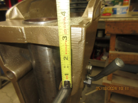
Next, I slipped the pulley onto the spindle splines and fully seated the assembly into the head casting. The pulley is fully seated when the top sheave is ~3/4" below the rim of the head casting.
full
full

The last step is to install the two pulley retaining screws.
full
 
To avoid these ads, REGISTER NOW!
OP
F

FrankLee

Well-known member
Joined
Sep 13, 2010
Messages
3,616
Location
seMI, 48317
DP#152 - Part 17.1 Model Badge and Head Trim Panel

full

Cleaning and Repairing

Many times, the badges and trim panels have dings and dents. DP#152 is no exception.
full
full

Often, the panel screws make the worst dents.
full
full
full

Because these components are thin aluminum, dings and dents can be easily bumped out. The key is to use a hammer with a convex face and a hard flat surface. I use this body hammer and this piece of solid-surface countertop material.
full

My first step is to clean both sides of these parts with mineral spirits. Do not use acetone or lacquer thinner to clean printed parts.
full
full

Then, gently bump out the dents. Notice how the sound changes when bumping out the larger dents.

Next, cleaner wax removes the remaining grime.
full
full
full

full
full
full

Lastly, buff off the wax.
full
full


DP#152 - Part 17.2

Installing

Earlier, I mentioned that I drilled and tapped the mounting holes for the badge and panel. Installation starts with buffing the head of the brass screws for the head trim panel.
full
full

The holes in the badge and panel had to be enlarged slightly for the machine screws.
full
full
full

The head trim panel and the model badge were installed.
full
full

full
full

full
full


OP
F

FrankLee

Well-known member
Joined
Sep 13, 2010
Messages
3,616
Location
seMI, 48317
DP#152 - Part 18.1, The Pivoting Motor Mount

This is the third and final version of the pivoting motor mount of this style. It has a clip and stud that threads into the head casting. The motor support base is very rusty and will require new paint.
full
full


Dismantling

First, I removed the shoulder screw, spring washer, latch and guide. With the screw back in place, I hammered out the threaded insert.
full
full
full

Next, I removed the nut and bumper from the stud.
full

Lastly, I removed the roll pins for the motor support rods with a press.
 
Last edited:
OP
F

FrankLee

Well-known member
Joined
Sep 13, 2010
Messages
3,616
Location
seMI, 48317
DP#152 - Part 18.2

Cleaning and Painting

The small parts and the rods were sonic cleaned. All except the stainless steel clip parts were soaked in citric acid.
full
full

full
full

The motor support base was cleaned with Grez-Off, rinsed and soaked in citric acid.
full
full


This morning, all parts were pulled from the CA, rinsed and dried.
full
full
full

The small parts were wire wheeled.
full
full
full

full
full

I started wire wheeling the motor support base on the bench grinder, but decided the angle grinder outdoors was a better idea. I finished wire wheeling the inside corners with a dremel.
full
full
full

The next steps were a wipe-down with acetone, then primed, then topcoat.
full
full

full
full

full
 
OP
F

FrankLee

Well-known member
Joined
Sep 13, 2010
Messages
3,616
Location
seMI, 48317
Frank,
On the 100 and 150 drill presses where do you prefer to install a power switch when you don’t have an original motor with the installed switch?
I do have an original 115.6962 motor with the built-in switch, but I also have, prefer and highly recommend a foot switch.


Cruzan80

Well-known member
Joined
Jul 22, 2015
Messages
4,262
Location
Denver, CO
Frank (or others), I may have asked this before, but (hopefully soon) getting to the point where I am thinning down a herd ad deciding which to keep. Any easy way to determine the best spindle/quill/combo amongst a few? Not sure if removing the spindle and sticking it in V-blocks on a surface plate would have the least variables, or if leaving it installed in the quill wouldn't really matter too much.
 
OP
F

FrankLee

Well-known member
Joined
Sep 13, 2010
Messages
3,616
Location
seMI, 48317
Frank (or others), I may have asked this before, but (hopefully soon) getting to the point where I am thinning down a herd ad deciding which to keep. Any easy way to determine the best spindle/quill/combo amongst a few? Not sure if removing the spindle and sticking it in V-blocks on a surface plate would have the least variables, or if leaving it installed in the quill wouldn't really matter too much.
I replaced all the unique internal 100 parts with 150 parts. IMO, a quill with the retaining ring is probably the most important upgrade. Also, you should keep a Jacobs 633C chuck if you have one.

You should be able measure run-out using a dial indicator with a magnetic base without removing anything.

I like the rapid-adjust feed stop, the pivoting motor mount and the feed handle hub/rods with the 1/2-13 threads.
 

Cruzan80

Well-known member
Joined
Jul 22, 2015
Messages
4,262
Location
Denver, CO
Yes, I was just referring to multiple spindles/quills and trying to select the "best" one. It will have a 633C on there, with locking ring. IIRC, I have a three 100 and a 150 combined to sort thru. I am aware of the differences for the other parts, and will swap as needed.
 
OP
F

FrankLee

Well-known member
Joined
Sep 13, 2010
Messages
3,616
Location
seMI, 48317
DP#152 - Part 19.1, The Motor

This motor is an Emerson Electric model 113.12120 with a date code of K66, October, 1966. It is a split phase, sleeve bearing motor and is probably the simplest and easiest motor to refurbish.
full

full
full

full
full


Dismantling

The first step is to run the motor and clean the pulley shafts. This may sometimes help the shaft slide through the sleeve bearing.
full
full

Next, remove the terminal cover plate and the ground screw.
full
full

At this point, It's a good idea to take a photo of the wiring.
full

Then, with needle nose pliers, pull the power cord spade connectors off the terminal board.
full
full

Remove the cradle clamps.
full
full

Next, remove the four nuts and the through-bolts.
full

Remove the motor from its cradle base.
full

With a blunt chisel or screwdriver and hammer, loosen the fan-side end frame and pull it off.
full
full
full

Pull out the rotor assembly.
full
full

With a blunt chisel or screwdriver and hammer, loosen the switch-side end frame, pull it off and turn it sideways.
full
full
full

Remove the two screws for the terminal bar.
full
full
full


Remove the two oil plugs.
full

This stator is remarkably clean!
full
full


Back to the rotor assembly... remove the three washers and the retaining ring from each end. Note the order of parts.
full
full

full
full


full
full

 
Last edited:
OP
F

FrankLee

Well-known member
Joined
Sep 13, 2010
Messages
3,616
Location
seMI, 48317
DP#152 - Part 19.2

Removing the Motor Badge


It's not always possible or practical, but IMO, a refurb is not complete if the badges are not removed. The panel screws for the motor badge on Emerson motors are installed into blind holes. There's no way to drive them out from the back side. Cutting a slot in the panel screw head is a common technique to remove them and is often effective. Here's how I do it...

I tape a large 1/4" washer over the panel screws to prevent damage to the badge. The washer on the left is one I used in the past. I apply wide tape over the new washer and cut out the hole. I then taped the washer over the panel screw head.
full
full

Below is my setup. I have a piece of plexiglass in a slot cut into a piece of wood for a face shield. I clamp the end frame onto the bench and cut the slot in the panel screw head with a Dremel. A 3/16" slotted screwdriver removes the panel screw.
Sometimes the head will break off. Check this post to see how I deal with that.
 
Last edited:
OP
F

FrankLee

Well-known member
Joined
Sep 13, 2010
Messages
3,616
Location
seMI, 48317
DP#152 - Part 19.3, Cleaning the End Frames

Clean the inboard and outboard metal rings and the area surrounding the oil port with acetone.
full
full
full

full
full

Mask the inboard and outboard metal rings and the area around the oil ports with tape. I use Dr Shrink tape. It's very tacky and sticks very well to make the sleeve bearings water tight. Trim the tape.
full
full
full

full
full
full

Spray on Grez-Off, scrub with small brushes rinse and dry.
full
full
full

full
full
full
full

Peel off the tape and admire your work.
full
full

Lastly, wire wheel the cradle rings and paste wax.
full
full

 
Last edited:
OP
F

FrankLee

Well-known member
Joined
Sep 13, 2010
Messages
3,616
Location
seMI, 48317
DP#152 - Part 19.4, Cleaning the Rotor Assembly

Except for the fan, the rotor assembly is in great shape.
full
full


I didn't want the governor assembly getting wet during cleaning, so I covered everything below the fan in plastic wrap.
full

Then I spayed the fan with Grez-Off and scrubbed the fins with a tooth brush. It was nasty! I followed up with a rinse, dry and compressed air. It's not perfect, but so much better.
full
full
full

full
full
full


Last edited:
OP
F

FrankLee

Well-known member
Joined
Sep 13, 2010
Messages
3,616
Location
seMI, 48317
DP#152 - Part 19.5, Cleaning the Stator Assembly

The top of the windings and the top inside edge of the stator case were dirty like the fan above. I just used a dry brush, a vacuum and compressed air to clean as much as possible.
full
full
full

full
full
full

I cleaned the top of terminal bar with WD-40 contact cleaner and cotton swabs. (I like CRC QD cleaner better.)
full

I wiped down the outside of the stator case with mineral spirits and finished cleaning with cleaner wax and buff.
full
full
full

full
full


DP#152 - Part 19.6, Cleaning the Motor Base

The motor base was particularly nasty with a thick layer of oily grime on the horizontal surfaces.
full
full
full

I started with a copper wire brush to remove the heavy dirt followed with a scrubbing with Grez-Off, rinse, dry and paste wax.
full
full
full

full
full
full


DP#152 - Part 19.7, Cleaning the Motor Small Parts

The terminal cover and badge were cleaned with mineral spirits and then cleaner wax.
full
full
full

The brackets, screws, bolts and nuts went a couple rounds in the sonic cleaner and then wire wheeled.
full
full

full
full
full
 
Last edited:
OP
F

FrankLee

Well-known member
Joined
Sep 13, 2010
Messages
3,616
Location
seMI, 48317
DP#152 - Part 19.8, Assembling the Motor

Because I detest panel screws so much, my first step is to drill (#36) and tap (6-32) the switch-side end frame for machine screws to reattach the model number badge. Then, I ran a tap through all other tapped holes to clean them out.
full
full
full

full
full
full

Then, I enlarged the holes in the badge to 5/32" for 6-32 x 1/4" button head socket screws. It's easy with a step bit by hand.
full

Next, install the badge.
Tip: When installing rectangular badges with two screws, bend the badge slightly concave between the screws and slightly convex on the ends. This ensures a flat installation.
full
full

full
full


About the stator and terminal bar wiring...

My swag is that the blue and yellow wires are attached to the start windings and the black and red wires are attached to the run windings.
full

There are two clusters of three terminals. The three terminals in each cluster are connected to each other. I found it puzzling as to why the blue and yellow spade connectors were installed perpendicular to the end frame and required sharp bends to be routed to the stator. I moved the blue and yellow connectors to the parallel spades (last photo). My new cord will utilize the threaded posts with ring terminals.
full
full

full
full

The next step was to reattach the terminal bar to the switch-side end frame.
full
full

Then, stand the stator on end, align the thru-bolt holes in the end frame with the slots in the stator and tap the end frame onto to the stator case.
full

Back to the rotor assembly...
Install the retaining ring onto the pulley shaft.
full
full

Then, install the steel cup washer. Verify that the tab is not sitting on the ear of the snap ring (I did that once). Then, install the rubber washer and the fiber washer. It's possible that the thicknesses of the fiber washers are different on each side. Because rotor spacing is critical, install the washers on the same side in which they were removed.
full

Repeat retaining ring and washer installation on the other end of the rotor.
full

Next, set the stator/end-frame assembly on its side, apply a drop of oil on the shaft near the washers and slide in the governor side of rotor assembly. There is a rubber washer inside the end frame. You will need to align the washer with the pulley shaft.
full
full
full

Next, set the motor upright. A jig or blocking will be required. Apply a drop of oil to the rotor shaft.
full

Slide the fan-side end frame onto the rotor shaft. Orient the oil port to align with the oil port on the switch-side end frame. Align the thru-holes with the stator slot and the thru-holes in the switch-side end frame. a flashlight is helpful to set the alignment. Tap the end frame onto the stator.
full
full
full

Lay the motor on its side and insert the thru-bolts. I insert the bolts from the switch side so the extended threads will be pointing down when the motor is installed on a drill press. Install and tighten the nuts.
full
full
full

Next, add oil to the oil ports. I usually apply about 8 drops in each side. Then, insert the oil plugs.
full
full

Next, insert the motor into the cradle base. Loosely assemble the clamps and install one on each side. Adjust the motor in the cradle and tighten the clamp screws.
full
full
full

The cord...
Set the cord next to the terminal opening and mark the insulation where the ground will reach the screw hole. Crimp on a strain relief hog ring on the mark. Trim the outer casing of the cord near the hog ring; about 1/4".
full
full
full

Trim the ground wire only long enough to reach the ground screw hole and attach a ring terminal. Install a short piece of shrink tube.
full

Repeat for the hot and neutral wires. Note that the hot wire goes to the copper terminal post and the neutral wire to the silver terminal post. Install nuts and ground screw.
full
full
full

Plug in the cord and test. Let it run for a minute, Look for smoke, smell for overheating, feel for heat and listen for the click during shutdown.


Lastly, install the screws and cover plate. Install the shaft guard.
full


full
full


Last edited:
OP
F

FrankLee

Well-known member
Joined
Sep 13, 2010
Messages
3,616
Location
seMI, 48317
DP#152 - Part 18.3, Assembling the Pivoting Motor Mount

The motor mount paint has been curing for eight days. It's time to reassemble.

This is the third and last version of the pivoting motor mounts of this style. It has the stud that threads into the head casting and a clip on the motor plate.
full

Because I removed the tiny threaded insert, I wanted to make sure it will stay put after reinstalling. I cleaned out its bore in the motor mount plate with a small wire brush to remove any paint. The insert was still a good friction fit, but I added a bit of retaining compound and drove it into the plate with a punch.
full
full

full
full

If that wasn't enough, I peened the other side with a center punch and verified the threads were okay with a 1/8-40 tap.
full
full

Next, I applied a bit of thread locker to the shoulder screw, installed the clip assembly and adjusted the screw for a good friction slide.
full
full

On to the motor support rods...
I tapped the roll pins into the rods just to get them started. I then pressed the roll pins with a vise so the end of the pin just barely protruded into the slot. This allowed the rod to be easily aligned with the hole in the motor plate. Notice that the rod mount is slightly bent. I straightened that after the pin was fully installed.
full
full
full

Next, with a c-clamp. I fully pressed the pin into the rod.
full
full

full
full

I repeated for the other rod and then test fit the mount into the head casting. The rods needed just a slight tweak for the mount to slide in and out smoothly and straight.
full
full

The last thing to do was to install two new rubber bumper washers onto the stud and replace the original pressed steel nut with a solid jam nut.
full
 
Last edited:
OP
F

FrankLee

Well-known member
Joined
Sep 13, 2010
Messages
3,616
Location
seMI, 48317
DP#152 - Part 20, Cleaning and Installing the Motor Pulley

full
full

Cleaning
First, I wire wheeled the key.
full

Next, the pulley was scrubbed with Grez-Off. It was so nasty, it took a few times to remove all the grime. Then a rinse and dry.
full
full

full
full

Then, each sheave and the edges were wire wheeled.
full
full
full

Installation
The first step was to run a tap through the female set screw threads to remove any dirt. Then, I sprayed the threads with electronic cleaner to remove any residual oil.
full
full

Next, I wire wheeled the set screw and dunked it in acetone to remove any residual oil.
full
full

Then, I applied some anti-seize to the pulley shaft. That looks like a lot, but I slid the pulley on and off and cleaned off the excess.
full

Next, I applied a drop of thread locker into the female threads in the pulley and a drop onto the set screw threads. Then, I started the set screw into the pulley.
full
full
full

The pulley was installed onto the shaft, the key was inserted and the set screw was tightened.
full
full

full
full


OP
F

FrankLee

Well-known member
Joined
Sep 13, 2010
Messages
3,616
Location
seMI, 48317
DP#152 - Part 21, Installing the Motor on the Motor Mount

First, about the geometry of the spindle pulley and the head casting...

The bottom plane of the spindle pulley is just slightly above the top plane of the rear plateau of the head casting.
full
full

The bores for the motor support rods on this head casting are ~3-1/4" below the rear plateau of the head casting.
full
full

I've seen slight variances of this measurement. Below is an early 150 that measured closer to 3-3/8".
1782243186331.png

On a properly assembled drill press, the spindle and motor shaft should be parallel to each other and the v-belt should be perpendicular to both. This reduces the wear on both pulleys and the v-belt. The only adjustable component is the height and pitch of the motor/pulley. Therefore, the motor/pulley should be installed so that the v-belt is as close to the rear plateau as possible without rubbing. I will install the motor onto the motor plate so that the belt will be ~3-3/8" from the motor support rods.

Installing the Motor onto the Motor Mount Plate

I prefer to install the motor with the motor mount off the head casting. I set the motor with base up and loosely attach the mount plate with two bolts. I attach a rule with a magnet. The rule is at the bottom of the pulley.
full
full
full

Then, I measured 3-3/8" from the top edge of the rod to the top edge of the rule. I centered the mount horizontally with the motor base, hand tightened the two upper bolts and installed and hand tightened the two lower bolts.
full
full
 
Last edited:
To avoid these ads, REGISTER NOW!
OP
F

FrankLee

Well-known member
Joined
Sep 13, 2010
Messages
3,616
Location
seMI, 48317
DP#152 - Part 22, Installing the Motor/Mount onto the Head Casting

First, I installed the stud all the way into the head casting and installed the two motor mount lock bolts into the head casting. Notice the lock bolt were ground to a bevel at the end of the threads. This will prevent the bolt from mushrooming.
full
full

I placed the v-belt in position and installed the motor and mount into the head casting. The v-belt is important here. It will prevent the motor with the pivoting mount from falling out of the head casting.
full


I pulled out the motor until the v-belt was taught and the motor plate was parallel to the back of the head casting.
full

I hand tightened the lock bolts and checked the belt for clearance. Perfect!
full

Next, I adjusted the stud and the jam nut by hand.
full
full

At this point, the nuts and bolts are mostly still hand tightened. There's always some tweaking required to square-up the motor mount and tighten the v-belt. When I was satisfied with the final adjustments, everything was tightened down.
full
full

full
full

full
full

It's time to test.

The v-belt will settle in to the pulleys and usually needs an adjustment after the drill press is used some.
 
Last edited:

Outlawmws

Well-known member
Joined
Aug 9, 2011
Messages
39,291
Location
The Badlands
Frank,

Seeing the centered holes in the motor plate at the bottom, I had a thought for using the table clamp screw(s) from a Craftsman RA saw to take the vertical load for adjusting the motor height. possibly even use 2; at the bottom of the bottom slots?

This type clamp screw

1782325627403.png

Here:

1782325734204.png
 
OP
F

FrankLee

Well-known member
Joined
Sep 13, 2010
Messages
3,616
Location
seMI, 48317
Frank,

Seeing the centered holes in the motor plate at the bottom, I had a thought for using the table clamp screw(s) from a Craftsman RA saw to take the vertical load for adjusting the motor height. possibly even use 2; at the bottom of the bottom slots?

This type clamp screw

1782325627403.png

Here:

1782325734204.png
That is interesting. I'm glad to see new ideas.

This morning, I started building a jig from plywood, but there were too many complicated variable dimensions using the bottom sheave of the motor pulley. I had to give up on that design. Even the way I did it above was somewhat awkward.

I ultimately want to make a universal jig that would work for all size Craftsman models from the 12-1/4", 13-1/2" and 15-1/2" 100s and 150s. I've got another idea I'm mulling over that I'll have to work on.
 

BSWS

Well-known member
Joined
Jun 2, 2019
Messages
360
Location
Tucson AZ
Notice the lock bolt were ground to a bevel at the end of the threads. This will prevent the bolt from mushrooming.

That's a simple thing I never thought of. Thanks again for sharing all of this. I really don't need a 3rd DP but it's making me want to do another one.
 
OP
F

FrankLee

Well-known member
Joined
Sep 13, 2010
Messages
3,616
Location
seMI, 48317
DP#152 - Part 23, Cleaning and Installing the Feed Handles

The feed handles are usually the last parts I install.

full
full

Dismantling

The first step is to remove the knobs from the rods. I clamped a coupling nut in a vise, tightened the rod with a jam nut and turned off the knob by hand.

full
full

full
full

Next, the rods spent some time in a hot citric acid bath.
full

Then, I installed the knobs on a mandrel in a drill and cleaned them with cleaner wax.
full
full


Next, I pulled the rods from the citric acid, dried and scrubbed each with steel wool. I put them back in the CA for another while. After, I chucked each rod, sanded with 1200 grit sandpaper and cleaner waxed with #0000 steel wool. These are not perfect, but they cleaned up much better than I expected... good enough for me.
full
full
full

Assembling and Installing

I used the same coupling nut/jam nut technique to reinstall the knobs. I installed only one feed handle in the hub at this time. I'll install the others after tensioning the spring.
full
full


Last edited:

y'sguy

Well-known member
Joined
May 1, 2010
Messages
1,331
Location
Tulsa, Oklahoma
As I was watching the knob polishing part, I was thinking to myself, when I do this type of thing, I always get it caught in the drill. :eek:
 
OP
F

FrankLee

Well-known member
Joined
Sep 13, 2010
Messages
3,616
Location
seMI, 48317
DP#152 - Part 24, Tensioning the Feed Return Spring

There is currently zero torsion on the spring. When tightening the spring, always rotate the hub/pinion in the counter-clockwise direction.
full

Tightening in the wrong clockwise direction will deform the spring.

1782470077803.png


Below are steps I take to tension the feed return spring on later Craftsman drill presses without the tension knob,
  1. Lock the quill.
  2. Draw out the hub to the right until the pinion gear disengages with the quill gear rack
  3. Rotate the hub counter-clockwise 1-1/2 revolutions.
  4. Unlock the quill and test feed return.
  5. Repeat if necessary
  6. I always have one handle facing forward/horizontal. This provides plenty of room around the chuck for installing and tightening bits.
full
full
full
full


I like a softer feed return. There is no need to have the quill slam up so hard. Also, IMO, letting go of the handle for a normal quill return is a bad practice.

The seller of this machine mentioned that the spring is not oem. This hub was rotated two full turns, but all springs/machines are different.


I installed the other two feed handles and consider this drill press is done.
full
full

 
OP
F

FrankLee

Well-known member
Joined
Sep 13, 2010
Messages
3,616
Location
seMI, 48317
DP#152 - Epilogue

DP#152 was an interesting machine. It had several typical and a few uncommon issues:
  • very grimy
  • moderately rusted
  • stuck column
  • oem rapid-adjust feed stop collar missing
  • oem spring replaced
  • fubar spindle retaining screw
  • burr on spindle pulley bearing shaft
When I first started this machine, I had no idea I'd be posting so much detail. In hindsight, I should have taken and posted more photos about dismantling for transporting and dismantling the head frame.

This drill press was a borderline candidate for a repaint, but I always lean toward saving original paint when possible. As is, it would still drill the same straight hole as if it were beautifully repainted.

I've never refurbished a machine in this sequence. I normally dismantle the entire machine and each sub-assembly, then clean all parts, then assemble the sub-assemblies, then finally assemble the machine.

Below are links to each post during the overhaul.
Part 1, Acquisition, Assessment, Disassembly Overview
Part 2, Extracting the Column
Part 3, Removing the Chuck from the Spindle
Part 4, Extracting the Pulley Retaining Screw
Part 5, Cleaning the Base
Part 6.1, De-Rusting the Column
Part 6.2, Cleaning the Column
Part 6.3, Turning the Column
Part 6.4, Installing the Column
Part 7.1, Cleaning the Table Lock
Part 7.2, Cleaning the Table
Part 7.3, Installing the Table
Part 8.1, Cleaning the Head Frame
Part 8.2, Cleaning the Head Frame
Part 9, The Outer Retaining Ring
Part 10.1, Dismantling the Hub, Pinion, Spring & Pin Assembly
Part 10.2, Cleaning the Hub, Pinion, Spring & Pin Assembly
Part 10.3, Assembling the Hub, Pinion, Spring & Pin Assembly
Part 10.4, Installing the Hub, Pinion, Spring & Pin Assembly
Part 11.1, Dismantling the Quill & Spindle Assembly
Part 11.2, Cleaning the Quill & Spindle Assembly
Part 11.3, Assembling the Quill & Spindle Assembly
Part 11.4, Installing the Quill & Spindle Assembly
Part 12.1, Dismantling the Quill Lock Assembly
Part 12.2, Cleaning the Quill Lock Assembly
Part 12.3, Assembling and Installing the Quill Lock Assembly
Part 13.1, Dismantling and Cleaning the Feed Stop Assembly
Part 13.2, Assembling the Feed Stop Assembly
Part 13.3, Installing the Feed Stop Assembly
Part 14.1, Dismantling the Chuck
Part 14.2, Cleaning the Chuck
Part 14.3, Assembling the Chuck
Part 14.4, Installing the Chuck
Part 15, Installing the Head Frame Assembly
Part 16.1, Dismantling the Spindle Pulley Assembly
Part 16.2, Cleaning the Spindle Pulley Assembly
Part 16.3, Assembling the Spindle Pulley Assembly
Part 16.4, Installing the Spindle Pulley Assembly
Part 17.1, Cleaning and Repairing the Model Badge and Head Trim Panel
Part 17.2, Installing the Model Badge and Head Trim Panel
Part 18.1, Dismantling the Pivoting Motor Mount
Part 18.2, Cleaning and Painting the Pivoting Motor Mount
Part 18.3, Assembling the Pivoting Motor Mount
Part 19.1, Dismantling the Motor
Part 19.2, Removing the Motor Badge
Part 19.3, Cleaning the End Frames
Part 19.4, Cleaning the Rotor Assembly
Part 19.5, Cleaning the Stator Assembly
Part 19.6, Cleaning the Motor Base
Part 19.7, Cleaning the Motor Small Parts
Part 19.8, Assembling the Motor
Part 20, Cleaning and Installing the Motor Pulley
Part 21, Installing the Motor on the Motor Mount
Part 22, Installing the Motor/Mount onto the Head Casting
Part 23, Cleaning and Installing the Feed Handles
Part 24, Tensioning the Feed Return Spring


One last thing...
IMO, once the head casting is installed on the column, it is very rare that it needs to be moved. When I sell a machine, I replace the head lock handle/bolt with a standard bolt. I will provide the buyer with the original head lock handle/bolt, but strongly recommend he use the standard bolt. I've seen too many accidental head crashes caused by loosening the original handle.
full
full

To make a new zinc plated bolt look old, soak it in vinegar for several days to remove the plating.
full
full

 
Last edited:

Outlawmws

Well-known member
Joined
Aug 9, 2011
Messages
39,291
Location
The Badlands
To make new zinc plated hardware look old, soak them in vinegar for several days to remove the plating.

If the goal is to remove the zinc plating, you can also soak it just minutes in muratic acid and it will completely strip the zinc.

Do enough zinc (it will stop reacting when its saturated) and the muraitic acid becomes zinc chloride, and is used as a soldering acid/flux for brass and copper. (I learned this little science experiment from the guy that taught me to de-solder and solder radiator tanks - RIP Carl)
 

y'sguy

Well-known member
Joined
May 1, 2010
Messages
1,331
Location
Tulsa, Oklahoma
@FrankLee

This reminds me, I can't recall, but my drill press version has the lever on the head. Which, as you said, isn't something I would adjust. Is it transferable to the table instead of a bolt, like mine has?

If so, I will switch them out.
 
OP
F

FrankLee

Well-known member
Joined
Sep 13, 2010
Messages
3,616
Location
seMI, 48317
If the goal is to remove the zinc plating, you can also soak it just minutes in muratic acid and it will completely strip the zinc.

Do enough zinc (it will stop reacting when its saturated) and the muraitic acid becomes zinc chloride, and is used as a soldering acid/flux for brass and copper. (I learned this little science experiment from the guy that taught me to de-solder and solder radiator tanks - RIP Carl)
I've used muriatic acid in the past. It also works great for removing rust in seconds, but it is very nasty stuff.
 
OP
F

FrankLee

Well-known member
Joined
Sep 13, 2010
Messages
3,616
Location
seMI, 48317
@FrankLee

This reminds me, I can't recall, but my drill press version has the lever on the head. Which, as you said, isn't something I would adjust. Is it transferable to the table instead of a bolt, like mine has?

If so, I will switch them out.
On a 100/150, the head lock lever can be used on a table with probably a slight modification.

The bolt portion for a head lock is ~4". The bolt portion of the table lock is ~3". You will likely need to extend the threads of the head lock with a 1/2-13 die for it to work for a table lock. The extra length should not be a problem on the table, but could be cut down.
 
OP
F

FrankLee

Well-known member
Joined
Sep 13, 2010
Messages
3,616
Location
seMI, 48317
I'm already missing my daily FrankLee training :)
Not much going on now. Maybe I should have assigned homework. LoL!

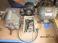
I am slowly working on the GE motor from logical. it's 1/2 hp 1725 rpm. I believe this motor is heavier than the common Packard motors. I have it torn down and have the end frames soaking in Purple Power to strip the three(?) layers of paint. The bearings are very stiff... especially the fan-side bearing.
IMG_1429.JPG IMG_1428.JPG

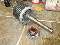
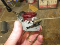
I found this very interesting... There are two screws that attach the governor assembly to the rotor; It comes off in one piece. I've had twelve GE motors and never saw this before.
IMG_1426.JPG IMG_1427.JPG
 
OP
F

FrankLee

Well-known member
Joined
Sep 13, 2010
Messages
3,616
Location
seMI, 48317
This is the Packard Craftsman motor I got from logical. It is a model 115.6963, 1/2 hp, 3450 rpm with a date code of March 1954. Based on the amount of sawdust inside, I'm presume it came off of a table saw.

It is virtually identical to a model 115.7429, which is also a 1/2 hp, 3450 rpm and a model 115.6962, which is a 1/2 hp, 1750 rpm.

full
full


Packard Craftsman Motor 115.6963 - Part 1, Disassembly

I think I take a rather uncommon approach when refurbishing these motors. Because the insulation on the original wiring is so brittle, I dismantle and reassemble them while disturbing the original internal wiring as little as possible. I've used this technique from the beginning when I didn't know what I was doing and I stuck with it, so it's not unusual to me.

This technique is somewhat more difficult, but IMO, it's easier than re-soldering in all new wiring. I will repair or replace wiring only when needed. This method has worked well for me.
  1. Run the motor, sand off the rust from the pulley shafts and mark the rotation direction.

  2. Remove the fillister-head machine screws, the felt retainer, the bearing felt, the end cap, the end cap gasket and the bearing spring from the fan-side frame
    full
    full


  3. Remove the fillister-head machine screws, the felt retainer, the bearing felt, the end cap, the end cap gasket from the switch-side frame,
    full
    full


  4. Remove the machine screws and terminal box cover.
    full
    full


  5. Cut the cord near the base.
    full


  6. Remove the acorn nuts and through bolts.
    full


  7. Remove the switch nut and ON/OFF plate.
    full


  8. Remove the machine screws and condenser/capacitor shield.
    full
    full


  9. Pull the remaining cord stub and the toggle switch from the base.
    full
    full


  10. Vacuum out some of the sawdust to find and remove the two base bolts.
    full
    full


  11. Feed the toggle switch, cord stub and capacitor through the base.
    full
    full


    This is the original power cord. It will be replaced.
    full


  12. Use a punch to loosen the fan-side end frame off the stator.
    full
    full


    The fan-side end frame will normally slide off the rotor bearing leaving the rotor inside the stator. This time, the rotor slid out of the switch-side bearing. Normally, a puller is required to push the rotor through the switch-side bearing and frame.
    full
    full
    full
    full


  13. Tap the rotor out of the fan-side end frame.
    full


  14. Remove the machine screws for the air cone.
    These screws are often very tight. Use the largest screwdriver that fits in the slotted screw head and use heavy downward pressure to loosen the screws.
    full
    full
    full


  15. Bend open the folds on the ends of the stator cover band.
    full
    full


  16. Twist the ends of the stator band against each other to separate the ends.
    full
    full
    full


  17. Slide the stator band out from underneath the stator.
    full


  18. Use a punch to loosen the switch-side end frame off the stator.
    full
    full


    A long cabinet screwdriver is very helpful for the following steps.
    full


  19. Stand the motor up on its end and remove the two screws for centrifugal switch and the one visible screw for the thermal switch.
    full
    full


  20. Insert the screwdriver into the gap between the end frame and the stator and remove the two screws for the terminal bar. A small flashlight is helpful here.
    full
    full
    full


  21. Reposition the statoe and end frame and remove the second screw for the thermal switch. The end frame is now free.
    full
    full


  22. Remove the fiber washers and screws from the terminal bar.
    full
    full


  23. Retrieve the remaining screws, switch shield and switch insulator.

  24. Remove the bearing from the end frame.
    full
    full


  25. Punch out the panel screws for the thermal switch badge.
    full
    full


    The stator and end frame are completely dismantled. All internal motor wiring is intact an unbroken.
    full
    full
    full


  26. Pull the bearing off the fan-side of the rotor. Use caution to pull on the outer race only
    full
    full
    full


  27. Slice the cord grommet off the base. A new, more appropriately sized grommet will be installed.
    full


  28. Drill off motor badge rivets.
    full
    full

full

full
 
Last edited:
OP
F

FrankLee

Well-known member
Joined
Sep 13, 2010
Messages
3,616
Location
seMI, 48317
Packard Craftsman Motor 115.6963 - Part 2, Cleaning the Stator and Rotor

full
full
full


  1. Use compressed air to blow sawdust off the stator.
    full


  2. Use compressed air to blow sawdust off the rotor.

  3. Use dry brushes, if necessary, to clean any residual sawdust from the stator assembly.
    full
    full

    full
    full


  4. Use dry brushes and steel wool, if necessary, to clean any residual dirt or sawdust from the rotor shaft segments between the bearings.
    full
    full
 
Last edited:
To avoid these ads, REGISTER NOW!
Top Bottom