To avoid these ads, REGISTER NOW!

#FabSpace

zmotorsports

ALLIANCE MEMBER
Joined
Oct 20, 2009
Messages
21,312
Location
Northern Utah
Stance looks great Matt. I know you wanted to keep low COG but I think that little extra lift will make a bigger difference off road and for the better.

I like your nail trick with filling holes. I've always used my Roper/Whitney punch to make a small slug and then place it in the hole to be filled, backed with a body dolly and hammered to expand or swell the plug then TIG weld the slug autogenously before metal finishing. It works well to make the hole invisible but your nail trick is much faster.

I've also used your trick to add metal back to brackets and such as things have to be "re-calibrated" from time to time. I've always said I prefer to working with metal over wood because if (when) I screw up and I can always add metal back in.:lol_hitti

Great job as usual Matt. Keep it up.:beer:
 
To avoid these ads, REGISTER NOW!
OP
L

lilscorpion

Well-known member
Joined
Mar 15, 2010
Messages
3,599
Location
Colorado
I've always used my Roper/Whitney punch to make a small slug and then place it in the hole to be filled, backed with a body dolly and hammered to expand or swell the plug then TIG weld the slug autogenously before metal finishing.


I know nails aren’t the the right way. Slugs make sense. How do you hold the little slugs in place? A magnet? With the nails I can easily hang on to the shank. Do you use the same thickness material for the slug or slightly thicker?

When I use the nails and fill with spot welds, there typically ends up some pinholes in the welds after metal finishing. I would think TIG would be much better for that purpose. I don’t have one at the moment but someday.
 
Last edited:

neilc

Well-known member
Joined
Jan 17, 2014
Messages
94
Location
Chicagoland
What a build! So you will undercoat the entire body when you are finished I guess?

Thanks for the great details and photos! Masterful!

neil
 
OP
L

lilscorpion

Well-known member
Joined
Mar 15, 2010
Messages
3,599
Location
Colorado
What a build! So you will undercoat the entire body when you are finished I guess?

Thanks for the great details and photos! Masterful!

neil

Thank you for the compliments, much appreciated. We will undercoat at least the wheel wells front and rear. It yet sure if we want to bother with the rest of the underside of the rub or not.
 
OP
L

lilscorpion

Well-known member
Joined
Mar 15, 2010
Messages
3,599
Location
Colorado
Wires everywhere. Difficult to view a build as a quality if there’s wires everywhere. Part of the problem is the sheer amount of wires that need to go through the firewall and no good way to do it. Typically you run the wires through a grommet that the factory has left for accessory upgrades but it’s not usually big enough to handle the dozens of wires which feed accessories like off road lights, a compressor, lockers, etc.

While working on the master cylinder upgrade I noticed a block-off on the firewall.

dc1bc68e4f7c1063e9866f1c5924936c.jpg

Looked it up and it’s a block off plate for where the clutch master cylinder would go for manual transmission equipped jeeps. Since I’ll never need it, I can use it to mount a bulkhead-like fitting for all of the auxiliary wires.

A peek behind the dash revealed it’s easily accessible and only held on with two 15mm nuts.

994d3095797c29e20c9925a8cf66f3d0.jpg

After popping the plate off, I got a better look at it. Two studs embedded in the plate, nothing special.

25ada60345f475f61f726a53a123aa8d.jpg

Backside has some kind of spray-on foam that serves as the seal against the firewall. I’ll have to use a gasket.

283b8dbdb9785fe10b6b87df88f987c7.jpg

Hole is big enough for a significant plug and/or grommet but, if enlarged, it’s plenty big enough to run more than one.

1ff1018044ae8f1d4b58bbce0a8fe544.jpg

Also browsed around and found there are aftermarket options do re-use the block off plate for the same purpose. Here’s one that’s available via Quadratec - https://www.quadratec.com/c/howto/how-run-wires-through-jeep-wrangler-tj-firewall

It’s simple really, you use a hole saw to cot through the block-off plate and then insert their grommet.

f60517d564f7d92c681ce0b9d05163f7.jpg

901017ef56ea9d3725182e0c7ced0a6b.jpg

Though that would be really easy, I kinda want something more like a bulkhead which I can pre-wire the inside of the vehicle for what we intend to run accessory-wise and then add them under the hood as we go. Here’s what I‘m thinking. I was going to use 2 bulkhead Deutsch connectors for that reason already anyway. This plate is almost perfectly sized for 2 to sit side by side.

82758db55daae727109e6c65103214a7.jpg

Took some basic dimensions

318da57acfc3dea664466f5ae5ccde39.jpg

4716bd3fcb86e27be227807874e85338.jpg

The plate is about 1/8th inch narrower than the plug. But there was enough room on the firewall to make the plate a little larger so I should be good.

3bb7a3e2e5199256542bfa89b1266f0d.jpg

Pulled down some 3/8” 6061AL off the shelf and marked some over-sized pieces to rough cut.

b6a437380565a850081c9d08100933af.jpg

Quick check for bolts. These were metric but I think I’ll convert them to something that’s more common in my shop - 3/8ths.

71b46cef7ef710f3f1400b94c39c445b.jpg

Cut to rough length on the bandsaw and then pre-drilled and tapped the holes.

8396e661d08e05d312578888993c3528.jpg

We’ll fake the studs using two button head screws like so and the rough out the profile.

e024469fbc2e4487d5531367f08371b0.jpg

Plan is to recess the profile of this flange into the plate and set 2 side by side. This will allow 24 wires to pass through the firewall and absolutely seal.

0ba8f4dd1d99bed25ab00e4f3d4b27ff.jpg

Cut in the shape of two of the flanges side by side into the plate first.

6679490b721def469aef9be54f2088f6.jpg

Then the through-holes for the body of the connector.

0c4f4bd7bbe76400503ee70a452733e9.jpg

A snug fit of the two next to each other while recessed, eliminates the need to screw them individually into the plate.

c323756e36febcdf549ee4b0330474ae.jpg

The side you can see will be what goes towards the firewall and will have a rubber gasket between.

26fef72c3e10b07bb231e17c9d4ae9aa.jpg

Side by side comparison new and old. Though I’m impartial, I think mine looks cooler.

1f3021e624ef6a2020397eb9b179e74d.jpg

Front-side of the new plate is what you’ll see inside the engine compartment.

110adc150270c7a2005eb4fb34c0e45f.jpg

I’ll have it powder coated with the remaining brackets and we’ll get it installed when we get back under the hood.
 

Attachments

  • f60517d564f7d92c681ce0b9d05163f7.jpg
    f60517d564f7d92c681ce0b9d05163f7.jpg
    418.3 KB · Views: 0
  • dc1bc68e4f7c1063e9866f1c5924936c.jpg
    dc1bc68e4f7c1063e9866f1c5924936c.jpg
    357.6 KB · Views: 0
  • 1f3021e624ef6a2020397eb9b179e74d.jpg
    1f3021e624ef6a2020397eb9b179e74d.jpg
    285.7 KB · Views: 0
  • 110adc150270c7a2005eb4fb34c0e45f.jpg
    110adc150270c7a2005eb4fb34c0e45f.jpg
    291.6 KB · Views: 0
  • 26fef72c3e10b07bb231e17c9d4ae9aa.jpg
    26fef72c3e10b07bb231e17c9d4ae9aa.jpg
    341.2 KB · Views: 0
  • c323756e36febcdf549ee4b0330474ae.jpg
    c323756e36febcdf549ee4b0330474ae.jpg
    340.2 KB · Views: 0
  • 0c4f4bd7bbe76400503ee70a452733e9.jpg
    0c4f4bd7bbe76400503ee70a452733e9.jpg
    341.7 KB · Views: 0
  • 994d3095797c29e20c9925a8cf66f3d0.jpg
    994d3095797c29e20c9925a8cf66f3d0.jpg
    309.5 KB · Views: 0
  • 25ada60345f475f61f726a53a123aa8d.jpg
    25ada60345f475f61f726a53a123aa8d.jpg
    293.2 KB · Views: 0
  • 283b8dbdb9785fe10b6b87df88f987c7.jpg
    283b8dbdb9785fe10b6b87df88f987c7.jpg
    292.7 KB · Views: 0
  • 1ff1018044ae8f1d4b58bbce0a8fe544.jpg
    1ff1018044ae8f1d4b58bbce0a8fe544.jpg
    66.9 KB · Views: 0
  • 901017ef56ea9d3725182e0c7ced0a6b.jpg
    901017ef56ea9d3725182e0c7ced0a6b.jpg
    412.6 KB · Views: 0
  • 82758db55daae727109e6c65103214a7.jpg
    82758db55daae727109e6c65103214a7.jpg
    315.3 KB · Views: 0
  • 318da57acfc3dea664466f5ae5ccde39.jpg
    318da57acfc3dea664466f5ae5ccde39.jpg
    321.3 KB · Views: 0
  • 4716bd3fcb86e27be227807874e85338.jpg
    4716bd3fcb86e27be227807874e85338.jpg
    305.7 KB · Views: 0
  • 3bb7a3e2e5199256542bfa89b1266f0d.jpg
    3bb7a3e2e5199256542bfa89b1266f0d.jpg
    329 KB · Views: 0
  • b6a437380565a850081c9d08100933af.jpg
    b6a437380565a850081c9d08100933af.jpg
    307.6 KB · Views: 0
  • 71b46cef7ef710f3f1400b94c39c445b.jpg
    71b46cef7ef710f3f1400b94c39c445b.jpg
    299.2 KB · Views: 0
  • 8396e661d08e05d312578888993c3528.jpg
    8396e661d08e05d312578888993c3528.jpg
    344.4 KB · Views: 0
  • e024469fbc2e4487d5531367f08371b0.jpg
    e024469fbc2e4487d5531367f08371b0.jpg
    371 KB · Views: 0
  • 0ba8f4dd1d99bed25ab00e4f3d4b27ff.jpg
    0ba8f4dd1d99bed25ab00e4f3d4b27ff.jpg
    306 KB · Views: 0
  • 6679490b721def469aef9be54f2088f6.jpg
    6679490b721def469aef9be54f2088f6.jpg
    370.8 KB · Views: 0

zmotorsports

ALLIANCE MEMBER
Joined
Oct 20, 2009
Messages
21,312
Location
Northern Utah
Fantastic work on the bulkhead fitting plate Matt.

We used the same manual clutch master cylinder hole in my son's LJ when we wired in some accessories but not as fancy as your connector setup.
 

90roadster

Well-known member
Joined
Jan 14, 2010
Messages
188
Location
Chicago Burbs
Fantastic work on the bulkhead fitting plate Matt.

We used the same manual clutch master cylinder hole in my son's LJ when we wired in some accessories but not as fancy as your connector setup.

Turned out awesome, good job! I like how you sunk them to be flush with the face. Was this on a CNC mill?
 
OP
L

lilscorpion

Well-known member
Joined
Mar 15, 2010
Messages
3,599
Location
Colorado
Thanks guys, we’re getting amped to drive this thing again! Little bling process after work. Got the Trail Gate for up.

756fa2905b8e3c405fc967d8e0b81aff.jpg

Closed. Now from the rear you can’t tell a color difference between the yellows because the whole rear end is the same. Sweet.

6bd5c32fba636a490a1fe64f6f0169b8.jpg

Andrew dropped on the tire carrier and started booting on the different pieces and parts.

73a8f5de17377c465453a05da79c171d.jpg

Working through rhetoric pics, this struck me as funny - notice how he’s still bolting stuff on and the sun went down completely in about 15 minutes. That’s Denver this time of year.

c50861ffb273d006bb163fd34082dbe4.jpg

After getting to stand back and see the tire carrier fully installed, I gotta say, Andrews idea of color matching the tire carrier to the body was pimp. Once we get the tires mounted I’m not so sure someone following the Jeep will easily be able to tell the tire isn’t floating.

a7c5be366ddfede62517b3e17a2af84b.jpg

Next we got the tail light bezels installed. So sweet.

04696a13b0049c6828043f282a6b912e.jpg

Fully assembled.

803d00b2d1c43a15f64a33dcb42eaa20.jpg

Andrew wasn’t feeling like the pics were truly showing the scale of the Jeep so here’s a Poser shot to put things into perspective. Andrew is 5’10”.

4a8095806335b99b1064c28fa6c948c1.jpg
 

Attachments

  • 756fa2905b8e3c405fc967d8e0b81aff.jpg
    756fa2905b8e3c405fc967d8e0b81aff.jpg
    374.6 KB · Views: 0
  • 6bd5c32fba636a490a1fe64f6f0169b8.jpg
    6bd5c32fba636a490a1fe64f6f0169b8.jpg
    374.8 KB · Views: 0
  • 73a8f5de17377c465453a05da79c171d.jpg
    73a8f5de17377c465453a05da79c171d.jpg
    371 KB · Views: 0
  • c50861ffb273d006bb163fd34082dbe4.jpg
    c50861ffb273d006bb163fd34082dbe4.jpg
    357.4 KB · Views: 0
  • a7c5be366ddfede62517b3e17a2af84b.jpg
    a7c5be366ddfede62517b3e17a2af84b.jpg
    375.5 KB · Views: 0
  • 04696a13b0049c6828043f282a6b912e.jpg
    04696a13b0049c6828043f282a6b912e.jpg
    342.3 KB · Views: 0
  • 803d00b2d1c43a15f64a33dcb42eaa20.jpg
    803d00b2d1c43a15f64a33dcb42eaa20.jpg
    375.5 KB · Views: 0
  • 4a8095806335b99b1064c28fa6c948c1.jpg
    4a8095806335b99b1064c28fa6c948c1.jpg
    389.6 KB · Views: 0

csp

Well-known member
Joined
Mar 23, 2010
Messages
5,719
Location
Franktown, CO
First time visitor to this thread Matt, 2+ months after you started it. I seem to never find free time these days. While scrolling through the first page the glint of yellow made me think you were going to show some build pictures of your old CJ5, lol.

The pics from TNT brought back some memories too. I have the very first set of sliders that Bob had bent many years ago, still in operation on my CJ5.

Shoot me a PM next time you need a box truck. I have pickups, flatbed trailers, and enclosed trailers that might be useful to you vs a rental.

It's a sweet build for sure! My soon to be 15yo thinks that the '73 CJ5 Super Jeep I found six months ago should be hers. It's the last thing I want her to drive and she may be 18 before I can find time to do anything to it, unfortunately. I picked it off the ground for the first time since bringing it home and found the left front wheelbearing hub flops all over the place. Yeah, it's far from being drivable.
 
Last edited:
OP
L

lilscorpion

Well-known member
Joined
Mar 15, 2010
Messages
3,599
Location
Colorado
First time visitor to this thread Matt, 2+ months after you started it. I seem to never find free time these days. While scrolling through the first page the glint of yellow made me think you were going to show some build pictures of your old CJ5, lol.

The pics from TNT brought back some memories too. I have the very first set of sliders that Bob had bent many years ago, still in operation on my CJ5.

Shoot me a PM next time you need a box truck. I have pickups, flatbed trailers, and enclosed trailers that might be useful to you vs a rental.

It's a sweet build for sure! My soon to be 15yo thinks that the '73 CJ5 Super Jeep I found six months ago should be hers. It's the last thing I want her to drive and she may be 18 before I can find time to do anything to it, unfortunately. I picked it off the ground for the first time since bringing it home and found the left front wheelbearing hub flops all over the place. Yeah, it's far from being drivable.


Yo! Man it’s been a while, glad you’re still doing well. Funny it reminded you of the CJ, it’s happened to me a time or two In the past few months too. Seems so long ago now. Seems to me to be an oldie now by today’s standards.

c00c851a9e373e970329faa615b52413.jpg

The earliest design of sliders we had were different that what most of the ones they have today. Do yours look like these? This was the earlier design.

494cd8ee57dc308d2d8a6c2202744ad1.jpg

I don’t blame your daughter for wanting it. From what Andrew is saying, jeeps are the rage in school for both boys and girls. I get it, they like them for the same reasons as we do. Can’t get it running?...come awn dad!! [emoji41]

Thanks for the offer, I might just take you up on it. Honestly I’ve had a few moments lately that make me want a truck. Like yesterday. Snow is piling up and the snow blower Sh*ts the bed. Wanted to buy another but no way to get it home. Turns out shoveling is easy for a 16 year old so I didn’t need one after all...though the idea of a Jeep/pickup hybrid (JT) is becoming interesting to me.

Matt


Sent from my iPhone using Tapatalk Pro
 

Attachments

  • c00c851a9e373e970329faa615b52413.jpg
    c00c851a9e373e970329faa615b52413.jpg
    69.5 KB · Views: 0
  • 494cd8ee57dc308d2d8a6c2202744ad1.jpg
    494cd8ee57dc308d2d8a6c2202744ad1.jpg
    66.1 KB · Views: 0

csp

Well-known member
Joined
Mar 23, 2010
Messages
5,719
Location
Franktown, CO
Front wheel bearings sound like a perfect daddy daughter project for a future Jeeper.:bounce:

I wish it were as easy as just new bearings. The snap ring at the end of the outer axleshaft is what kept the entire wheelbearing assembly from coming off the spindle. There was nothing left of the outer bearing, the race on that one had to be cut off of the spindle. Inner bearing took a puller to remove from the spindle. Wheelbearing hub is trashed and I'm hoping the spindle nut threads on the spindle aren't beyond re-using it.

Good thing I hoard old CJ parts!
 
To avoid these ads, REGISTER NOW!
OP
L

lilscorpion

Well-known member
Joined
Mar 15, 2010
Messages
3,599
Location
Colorado
The stock braking system will be no match for the new one ton axles so I’ve been researching upgrades. I found a few different versions of master cylinder upgrades but what appeared to be the easiest involves swapping in a master cylinder off of a ’99 Dodge 2500 which is a direct bolt-in with only a little fabrication. Sourcing one at the local parts store was easy and I think I have just enough time after work tonight to knock it out.

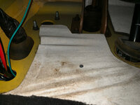
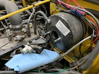
Started with draining and removing the factory unit. Believe it or not it’s empty here, that’s just how dirty the brake fluid was.

4f3b5a7fa45832cd06f408aae7d4f802.jpg

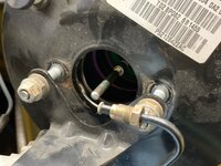
Brake lines removed then pop off the nuts that retain the proportioning valve and then the retention lock nuts.

3164917047bfc43bb865ea937343d487.jpg

f2d0e22b2e7b03b6b4e9a0c491d88274.jpg

After so many involved aspects of this project, a less complicated mod like this one is a nice change. I’m a minute and a half in and I’m ready to start in on the conversion. The most significant fabrication is to solve a problem with this little guy. This 1/4-inch diameter rod depresses the master cylinder and, based on the articles, is just short enough that it doesn’t have enough adjustment to support and will need to be replaced.

d35da86d369fecbadc643099898dbfe2.jpg

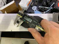
Here’s where a little planning makes a mod so much easier. Goal is to take measurements so I know exactly where the rod is set now, how much it needs to grow, make a new one exactly the right length, and then install it exactly where it (should) need to be for the new master cylinder.

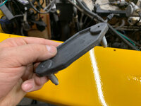
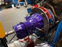
Here’s the two side-by-side. The factory unit is top left, Dodge unit lower right. The casting and piston on the base appears to be maybe half again larger which should make a significant difference in braking power.

674b11eb373d02971e1a9b6ca72a392b.jpg

That being said, the business end doesn’t appear to be all that different except for the new one doesn’t have a guide tube for the rod.

6bba4ccc84320f254e25aef08cd28241.jpg

I worked back and forth between the units taking offset measurements for the depth of the guide tube

41c4a482a509577d3cab6e4b2fd2dd58.jpg

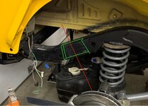
And the distance that the casting sits inside the booster.

0228ff144fe25a03c4e74bbeeed71683.jpg

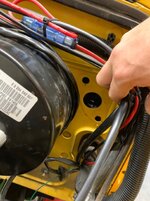
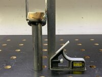
Then took a reference measurement to see how far inside the booster the rod was. After I do the math, I should be able to use this measurement to check my work.

4d5c216d72116ff800ac28818dd6fff7.jpg

With the basic measurements jotted down on a notepad, I removed the rod from the booster. I then took one final measurement of where the retaining shaft was in relationship to the face of the booster. This allowed me to figure out how much adjustment was possible with this little guy.

143d6f71efd8401b756daf8dce96a2ab.jpg

The rod was set fairly deep, about 4 threads in.

bf81bb6ceb393b22bc5dbb2891f261d3.jpg

Which leaves me with likely less than a half inch of adjustment.

3815c9ac60b4517d352fbd70ffc367a5.jpg

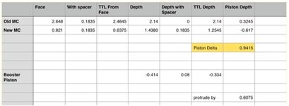
Now to figure out what is actually needed. I created a numbers worksheet that handled the math for me after entering the data points. The “piston depth” in the far right column is where the piston was/will need to be in relationship to the face of the booster (same as the flange on the master cylinder). For this master, I need a rod that is almost an inch longer so the one I have won’t work.

04cd6a71433e629ebccc35223ec05d7b.jpg

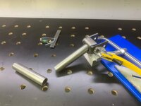
As luck would have it, the rod has 1/4-28 threads and is dimensionally the same as a 1/4” bolt. Quick trip to the hardware store to pick up a 3” grade 8 bolt as a starting point (get 2 because, well you know).

98c47597089a1e23520fef00e1a52313.jpg

Believe it or not, I cut this one handed while looking through my cell phone so I could take this picture. Remember I had a second bolt (no I didn’t need to use it).

aba63cf7c42c051cd0ec206b629b9f2d.jpg

Nice thing about Grade 8 hardware, I know that the thread length on this bolt is 1” so I can easily determine if where I cut makes sense.

54a71c89603400b20a0271f299beb3e1.jpg

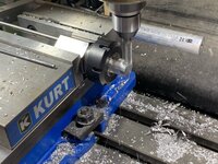
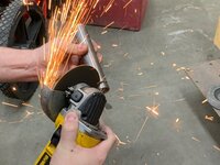
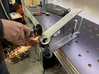
Now to the lathe. I’m going to flatten and then round the nose of this bolt shaft to match the profile of the factory rod. I chuck it up in an ER32 Collet chuck so I can get at it a little better without risking the chuck jaws.

7f62e3b3da4835114fb8eb45622a554e.jpg

This really is maybe a minute or so activity. I barely touch the part while making a half radius motion. Notice the cardboard below the chuck. That’s to prevent the dust and sparks from landing on the ways of the lathe. They’re no good for it.

1c5b81804f90ebaab8ce65bf0132c253.jpg

Close enough I’d say.

e3d3f67cd48ec6de34b7db39f2a242aa.jpg

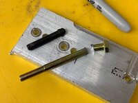
Not bad for spit ballin it. Black line signifies where the screw was adjusted previously and the new rod is just shy of .900 longer.

db54bcfba3b3b290b123099ce6de70b2.jpg

Hand threaded it into the retainer and set it approximately .600 extruded from the face.

9b282e93f901494117cedc6cdf9c7b14.jpg

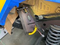
And adjusted it to be sticking out exactly the .6075 that my spreadsheet indicated as the new adjustment length. As I started putting it all back together, I found that the proportioning valve bracket didn’t fit well around the new master cylinder housing which makes sense given the difference in housing size.

44f3b181edda55c07ed36b79e524e773.jpg

So out comes the carbide burr to touch it up.

1481bbe1da21e067ee23c40d5953ecf3.jpg

And we’re moving on again.

4658437d0b7471cda2cb59ba31d1dfd2.jpg

I had read that the brake lines between the master and the proportioning valve may not be long enough to reach but I wanted to wait and see before buying lines. Unfortunately the write-ups were completely correct though, there’s no way they’ll make it no matter how I bend the lines. I’ll have to stop and get some tomorrow or figure out another way.

4f5bc7689341537fe22e0ddb6da6f5c2.jpg

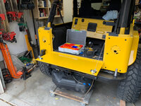
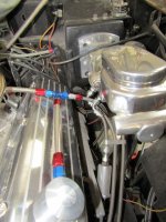
Brake lines for the calipers are on order and I’ll bleed the system as soon as they arrive. The setup looks so similar, it almost doesn’t look like I did anything.

c95d226d20a1b66b1657af749e43d7f8.jpg

Wait…there’s one more thing I should do. I’m not a huge fan of letting peepers easily be able to see all of the mods I do to vehicles. I prefer to give them things to find and it’s those things that typically uncover the enthusiasts who really know their stuff. In this case, I don’t really want the master to look aftermarket so swapping the factory cap back on is preferred.

2b7a6275fd0474baff93a54d1070f22a.jpg

There, now that looks better.

87efb61652100a45ea2f716b936e1bd4.jpg

Now to deal with the brake lines. The new master cylinder is now mis-aligned with the brake lines by almost exactly 1 1/2-inches. There’s two ways i came up with to solve this problem - (1) cutting the bracket and moving the proportioning valve forward 1 1/2” y adding In some material or (2) making new brake lines.

Though I can flare brake lines, I’ve been known to mess up occasionally so I figured I’d go
The metal fab route. Right about as I was about to cut the bracket so I could weld in a 1 1/2-inch spacer it occurred to me that I wouldn’t even need to make an adapter if the stud was, say, 1 1/2-inches longer and I could simply use a spacer to set it forward just enough...hmm.

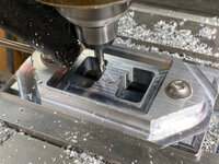
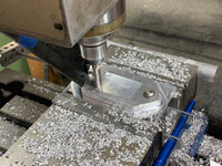
Concept is to make a spacer that threads on to the existing stud that has a stud of its own. I started with a piece of aluminum faced off square and chucked it in an ER40 6-sided block.

1de29e72cb236836a25f2f631d3c928a.jpg

To get a hex it’s really kinda easy, machine a flat and then rotate it and machine another...6 total times.

e9a91383aae3cba2cc67759c3e771d73.jpg

With the hex machined, I moved the entire assembly to the lathe and chamfered then square edges.

59434f7b7f8c45cabd9b9b35434589f3.jpg

Next step is to drill and tap to match the studs on the master cylinder. In this case, pre-drill to .266 and tap to 8mm x 1.25.

2e1d53f17c19a6baabd41dd074b87f18.jpg

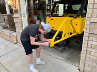
Now to test fit mocking bolts as the studs.

d2bf64ef1a126850307815320ba5bc38.jpg

The the stand-off moves the entire assembly forward enough now so the brake brake lines match up to the new master cylinders holes. Proof.

6c8b27088084ebb533e1fb778864a037.jpg

The the stand-off moves the entire assembly forward enough now so the brake brake lines match up to the new master cylinders holes. Proof.

41c134c6e3549719c7eff62fb630c764.jpg

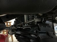
And with the threaded studs in place, the. It’s can now hold the proportioning valve bracket where it needs to be.

f8cc7f2724169e5c10afca83e830bfd6.jpg

And the brake lines can now be threaded into the master cylinder factory-ish. Hindsight I wish I would have thought about machining the stand-off so it would have a pocket on the back so it could conceal the nut behind it. Too much work to do it now so good enough.

716324f30e9b10051ee6848345890230.jpg

Thanks for following along.
 

Attachments

  • 4f3b5a7fa45832cd06f408aae7d4f802.jpg
    4f3b5a7fa45832cd06f408aae7d4f802.jpg
    77.2 KB · Views: 0
  • 1c5b81804f90ebaab8ce65bf0132c253.jpg
    1c5b81804f90ebaab8ce65bf0132c253.jpg
    28.2 KB · Views: 0
  • e3d3f67cd48ec6de34b7db39f2a242aa.jpg
    e3d3f67cd48ec6de34b7db39f2a242aa.jpg
    24.4 KB · Views: 0
  • db54bcfba3b3b290b123099ce6de70b2.jpg
    db54bcfba3b3b290b123099ce6de70b2.jpg
    33.1 KB · Views: 0
  • 9b282e93f901494117cedc6cdf9c7b14.jpg
    9b282e93f901494117cedc6cdf9c7b14.jpg
    84.8 KB · Views: 0
  • 44f3b181edda55c07ed36b79e524e773.jpg
    44f3b181edda55c07ed36b79e524e773.jpg
    34.6 KB · Views: 0
  • 1481bbe1da21e067ee23c40d5953ecf3.jpg
    1481bbe1da21e067ee23c40d5953ecf3.jpg
    89.6 KB · Views: 0
  • 4658437d0b7471cda2cb59ba31d1dfd2.jpg
    4658437d0b7471cda2cb59ba31d1dfd2.jpg
    39.2 KB · Views: 0
  • 4f5bc7689341537fe22e0ddb6da6f5c2.jpg
    4f5bc7689341537fe22e0ddb6da6f5c2.jpg
    81.1 KB · Views: 0
  • c95d226d20a1b66b1657af749e43d7f8.jpg
    c95d226d20a1b66b1657af749e43d7f8.jpg
    57.5 KB · Views: 0
  • 2b7a6275fd0474baff93a54d1070f22a.jpg
    2b7a6275fd0474baff93a54d1070f22a.jpg
    39.3 KB · Views: 0
  • 87efb61652100a45ea2f716b936e1bd4.jpg
    87efb61652100a45ea2f716b936e1bd4.jpg
    52 KB · Views: 0
  • 1de29e72cb236836a25f2f631d3c928a.jpg
    1de29e72cb236836a25f2f631d3c928a.jpg
    99.7 KB · Views: 0
  • e9a91383aae3cba2cc67759c3e771d73.jpg
    e9a91383aae3cba2cc67759c3e771d73.jpg
    102.8 KB · Views: 0
  • 7f62e3b3da4835114fb8eb45622a554e.jpg
    7f62e3b3da4835114fb8eb45622a554e.jpg
    45.9 KB · Views: 0
  • 54a71c89603400b20a0271f299beb3e1.jpg
    54a71c89603400b20a0271f299beb3e1.jpg
    39.6 KB · Views: 0
  • aba63cf7c42c051cd0ec206b629b9f2d.jpg
    aba63cf7c42c051cd0ec206b629b9f2d.jpg
    76 KB · Views: 0
  • 3164917047bfc43bb865ea937343d487.jpg
    3164917047bfc43bb865ea937343d487.jpg
    96.1 KB · Views: 0
  • f2d0e22b2e7b03b6b4e9a0c491d88274.jpg
    f2d0e22b2e7b03b6b4e9a0c491d88274.jpg
    106.5 KB · Views: 0
  • d35da86d369fecbadc643099898dbfe2.jpg
    d35da86d369fecbadc643099898dbfe2.jpg
    95.3 KB · Views: 0
  • 674b11eb373d02971e1a9b6ca72a392b.jpg
    674b11eb373d02971e1a9b6ca72a392b.jpg
    72.4 KB · Views: 0
  • 6bba4ccc84320f254e25aef08cd28241.jpg
    6bba4ccc84320f254e25aef08cd28241.jpg
    67 KB · Views: 0
  • 41c4a482a509577d3cab6e4b2fd2dd58.jpg
    41c4a482a509577d3cab6e4b2fd2dd58.jpg
    83.1 KB · Views: 0
  • 0228ff144fe25a03c4e74bbeeed71683.jpg
    0228ff144fe25a03c4e74bbeeed71683.jpg
    84.6 KB · Views: 0
  • 4d5c216d72116ff800ac28818dd6fff7.jpg
    4d5c216d72116ff800ac28818dd6fff7.jpg
    88.7 KB · Views: 0
  • 143d6f71efd8401b756daf8dce96a2ab.jpg
    143d6f71efd8401b756daf8dce96a2ab.jpg
    67.8 KB · Views: 1
  • bf81bb6ceb393b22bc5dbb2891f261d3.jpg
    bf81bb6ceb393b22bc5dbb2891f261d3.jpg
    69.7 KB · Views: 1
  • 3815c9ac60b4517d352fbd70ffc367a5.jpg
    3815c9ac60b4517d352fbd70ffc367a5.jpg
    72.6 KB · Views: 1
  • 04cd6a71433e629ebccc35223ec05d7b.jpg
    04cd6a71433e629ebccc35223ec05d7b.jpg
    25.4 KB · Views: 0
  • 98c47597089a1e23520fef00e1a52313.jpg
    98c47597089a1e23520fef00e1a52313.jpg
    75.7 KB · Views: 0
  • 59434f7b7f8c45cabd9b9b35434589f3.jpg
    59434f7b7f8c45cabd9b9b35434589f3.jpg
    57.1 KB · Views: 0
  • 2e1d53f17c19a6baabd41dd074b87f18.jpg
    2e1d53f17c19a6baabd41dd074b87f18.jpg
    63.9 KB · Views: 0
  • d2bf64ef1a126850307815320ba5bc38.jpg
    d2bf64ef1a126850307815320ba5bc38.jpg
    79 KB · Views: 0
  • 6c8b27088084ebb533e1fb778864a037.jpg
    6c8b27088084ebb533e1fb778864a037.jpg
    69.3 KB · Views: 0
  • 41c134c6e3549719c7eff62fb630c764.jpg
    41c134c6e3549719c7eff62fb630c764.jpg
    67.9 KB · Views: 0
  • f8cc7f2724169e5c10afca83e830bfd6.jpg
    f8cc7f2724169e5c10afca83e830bfd6.jpg
    70.8 KB · Views: 0
  • 716324f30e9b10051ee6848345890230.jpg
    716324f30e9b10051ee6848345890230.jpg
    81.1 KB · Views: 0

zmotorsports

ALLIANCE MEMBER
Joined
Oct 20, 2009
Messages
21,312
Location
Northern Utah
Excellent work and fantastic write-up Matt.

I couldn't agree more about doing homework and having a solid plan when it comes to mods. They turn out so much better and look less "half-assed" when you do that and yours looks factory. I too prefer to have things hidden in plain site when it comes to mods, especially on certain vehicles. A street rod or custom bike I'm ok with having the mods in your face but on a daily driver that I'm trying to keep OEM looking yet is heavily modified, like you I prefer to keep things hidden and only the true enthusiasts can tell the difference.

Great job Matt.:bowdown::bowdown:
 

Bob Heine

ALLIANCE MEMBER
Joined
Oct 24, 2009
Messages
10,703
Location
Boca Raton, Florida
Matt, that's a very nice modification. Much better than the fool who replaced the vacuum power brakes with hydroboost to install tall valve covers on a big block Corvette.
attachment.php
 

Attachments

  • Hydroboost.jpg
    Hydroboost.jpg
    95.3 KB · Views: 1,467
OP
L

lilscorpion

Well-known member
Joined
Mar 15, 2010
Messages
3,599
Location
Colorado
Matt, that's a very nice modification. Much better than the fool who replaced the vacuum power brakes with hydroboost to install tall valve covers on a big block Corvette.
attachment.php


Tho I too have wanted tall valve covers on a bbc with limited space, I could not have brought myself Togo hydro-boost to get there...though he did choose to polish the turd so there’s that. [emoji16]
 
OP
L

lilscorpion

Well-known member
Joined
Mar 15, 2010
Messages
3,599
Location
Colorado
Trying to get a dozen things ******* enough such that I can post an update.

...and with much disappointment - my son was driving my JK and it appears the trans is smoked. Just about ruined my inertia. It’s moments like this that not having a bigger garage kills me. Now we have 2 undriveable jeeps. [emoji107]


Sent from my iPhone using Tapatalk Pro
 

zmotorsports

ALLIANCE MEMBER
Joined
Oct 20, 2009
Messages
21,312
Location
Northern Utah
Trying to get a dozen things ******* enough such that I can post an update.

...and with much disappointment - my son was driving my JK and it appears the trans is smoked. Just about ruined my inertia. It’s moments like this that not having a bigger garage kills me. Now we have 2 undriveable jeeps. [emoji107]


Sent from my iPhone using Tapatalk Pro

That ***** Matt. Sorry to hear that and hope you can get your drive revigorated. I know what it's like to be in the middle of one project and something else on another vehicle pop up that just ***** the energy out of ya and causes you to lose steam.

I have to tell myself in order to eat an elephant it has to be one bite at a time so prioritize tasks and take one on at a time. I know it's much easier said than done though.

Best of luck and keep plugging along.
 
OP
L

lilscorpion

Well-known member
Joined
Mar 15, 2010
Messages
3,599
Location
Colorado
We’re continuing to pick away at fine-tuning activities today on the front end. As we were working towards finalizing the front suspension we noticed that the front end wasn’t tracking the same on the driver and passenger side. Now in a radius arm setup, this is a ridiculous thing to see because the differential is connected to the chassis in 3 places. Either control arm at the chassis side (just under the seats) and one is the trac-bar which cycles perpendicular to the chassis. As we cycled the suspension we realized that the driver’s side upper link on the radius arm was coming in contact with the Dynatrac bridge at ride height. As the driver’s side tire begins to stuff in the wheel well, the radius arm cannot twist in the housing side upper bushing which caused the axle to go into bind. The driver’s tire pushes forward in the wheel well and the passenger’s side goes hard into the rear fender.

0692fa3878b6f8b7a71dfbe702842177.jpg

Gave Bob a call up at TNTCustoms and he shipped me out a set of deconstructed upper links. What I’ll do is rotate the link end so it runs parallel to the upper bridge. Simple triangle math allowed me to figure out how to mock it up on the bench so I could think less.

0ef929c2f75ce1fb4413170aa7ce0164.jpg

I like to use higher-tech tools and processes whenever possible but sometimes doing so just makes a basic mod take way too long. Using a sharpie I mark the angle I’m looking for.

68513f09d39da406fa5fc84c5f8e3a7d.jpg

And free-cut the tubing along the angle with the 4.5” grinder wearing a cut-off wheel. Sparks are cool.

b2494b279853718bc466c8d9b82c3990.jpg

Something like this should do the trick. The tubing fits inside the hole and I’ll weld around the outside and the inside to make sure it fuses into a single assembly. Kinda hard to believe that a piece of .120 DOM and a bracket made out of 3/16” steel plate will be strong enough to withstand the torque applied to it when the radius arms go into bind.

92287eb0e0237dcc60686337584d0156.jpg

The bracket didn’t come out of the brake perfect, it’s left slightly under bent by design. This allows it to fit inside a fixture which pulls the sides into perfect square with the bolt holes right before welding. Since I’m finishing on the bench, I have to do so a little more caveman like. I start by squaring one side and burning it in. Then I tac the bracket to the tube and use a square to pull it into squareness with the tubing. Here you can see it needs just a tweak.

dd4b480c8cc3e342bfca0ae7125f361b.jpg

Fiddle fiddle, putz putz…and I’m able to burn it home.

027ea2982d9d4b85fa728a9c0733ed3e.jpg

After a little clean up on the arm, I get it all back together and get it installed.

4d31f1c8cd2533280d82270193e739b8.jpg

Now we have plenty of space between the control arm end and the housing bridge.

bc50a88beb404c4c66ea01263bcfab84.jpg

With the corrected uppers in place, we again cycle the front suspension to see if we’ve solved the problem. The passenger’s side now has room to breathe and the driver’s side matches. Fixed.

10044fe88f6482e021f2885f1f51dd57.jpg

Thanks for following along.
 

Attachments

  • 0692fa3878b6f8b7a71dfbe702842177.jpg
    0692fa3878b6f8b7a71dfbe702842177.jpg
    78.8 KB · Views: 1
  • 0ef929c2f75ce1fb4413170aa7ce0164.jpg
    0ef929c2f75ce1fb4413170aa7ce0164.jpg
    56.6 KB · Views: 0
  • 68513f09d39da406fa5fc84c5f8e3a7d.jpg
    68513f09d39da406fa5fc84c5f8e3a7d.jpg
    62.6 KB · Views: 0
  • b2494b279853718bc466c8d9b82c3990.jpg
    b2494b279853718bc466c8d9b82c3990.jpg
    77.5 KB · Views: 0
  • 92287eb0e0237dcc60686337584d0156.jpg
    92287eb0e0237dcc60686337584d0156.jpg
    42.2 KB · Views: 0
  • dd4b480c8cc3e342bfca0ae7125f361b.jpg
    dd4b480c8cc3e342bfca0ae7125f361b.jpg
    51.7 KB · Views: 0
  • 027ea2982d9d4b85fa728a9c0733ed3e.jpg
    027ea2982d9d4b85fa728a9c0733ed3e.jpg
    73.9 KB · Views: 0
  • 4d31f1c8cd2533280d82270193e739b8.jpg
    4d31f1c8cd2533280d82270193e739b8.jpg
    65.1 KB · Views: 0
  • bc50a88beb404c4c66ea01263bcfab84.jpg
    bc50a88beb404c4c66ea01263bcfab84.jpg
    56.4 KB · Views: 0
  • 10044fe88f6482e021f2885f1f51dd57.jpg
    10044fe88f6482e021f2885f1f51dd57.jpg
    71.9 KB · Views: 0

zmotorsports

ALLIANCE MEMBER
Joined
Oct 20, 2009
Messages
21,312
Location
Northern Utah
Excellent recovery Matt.

I worried about that on my son's WJ as well so when we mocked the front suspension up to build the upper links we angled the upper axle end so it wouldn't contact the center section. Even during mock up we still cut it a bit to close as we noted when off-road in Moab in October at stuff on the driver's side it was still quite close to contacting the cast housing.

Great work as usual Matt.

How's the transmission issue coming on the JK? Did you get that sorted out yet?
 
OP
L

lilscorpion

Well-known member
Joined
Mar 15, 2010
Messages
3,599
Location
Colorado
Excellent recovery Matt.

I worried about that on my son's WJ as well so when we mocked the front suspension up to build the upper links we angled the upper axle end so it wouldn't contact the center section. Even during mock up we still cut it a bit to close as we noted when off-road in Moab in October at stuff on the driver's side it was still quite close to contacting the cast housing.

Great work as usual Matt.

How's the transmission issue coming on the JK? Did you get that sorted out yet?


Thanks Mike. Always good to get the inertia back.

The Jk - well “we” did in fact smoke the trans. Not sure how honestly because I really don’t think Andrew was beating it yet it’s a NAG so it should have been able to handle quite a bit they tell me. What ever, forward. I was going to pull it but a local shop called ATSDiesel apparently is kinda ninja with the NAG and I happened to get Black Friday prices so I’m going to have them build one and do the install. Figured it was easier than attempting to straddle 2 torn apart jeeps in the garage at once. I dropped it off Saturday and the owner happened to be there and walked me through their process. As luck would have it, they were just about to run a NAG on their dyno...super cool.

622f13670d277ae37a3862e40e9c2632.jpg

Im hoping they can get me the Jeep back before Christmas but I’ll know more when I check in tomorrow. Hopefully good news. As they say, I'm making every attempt to let it be a good thing and attempt to enjoy the process along the way.

Matt
 

Attachments

  • 622f13670d277ae37a3862e40e9c2632.jpg
    622f13670d277ae37a3862e40e9c2632.jpg
    98.8 KB · Views: 2
Last edited:
OP
L

lilscorpion

Well-known member
Joined
Mar 15, 2010
Messages
3,599
Location
Colorado
Since we cut out the mid-bed crossmember to re-located the gas tank, we no longer have the factory upper shock mounts. A common mod in jeep builds is to move them outboard which allows the use of a much taller shock mount (which enables the use of taller shocks). TNT Customs makes a fab kit that’s designed specifically for this reason. This is one of the rear upper shock mounts.

97e6f991b913502ae8fbcebec231bad6.jpg

The shock mounts get frenched into the frame. To get them lined up, there’s a sequence of steps you go through to get the installed at the correct angle in reference to the rear axle but it’s nearly dummy proof as long as you have a large square, which of course we do.

ac30d7597fa0cfd3db13bdafb4132586.jpg

With the square you pencil in a line perpendicular to the sloped part of the frame using the fat side of the ruler on the differential side. That width of the square is how far off the diff the shock brackets sit so it’s almost a no-braininer. Good thing, this activity has to be a cut once affair.

856e52c9b2b3ee5c75e84c84dcc82178.jpg

With measurements taken, I mock the bracket mocked up to get an idea of where it’s going to sit. It’s this moment that we now need to think about shocks. It’s really really easy to just cut the shock mounts in and assume that there are shocks out there that will work but experience has proven that finding shocks in the length you need isn’t always easy. Narrowing in on shocks can be challenging so I like to make it as easy on myself as possible. All I really care about is the collapsed length and usable travel length. The only measurement I need to take then is the collapsed length which means I need to cycle the suspension and take a few measurements. Measuring from just below the axle tube (assumed location of the lower shock mount) to the mock location of the upper I get ~14.625”.

8555c2df3b266f75b6a27a1ed3ecd66e.jpg

Front differential is easy since we’ve finalized all of the brackets and the upper shock mount is stock. A front shock can have a minimum length of 16.5” (collapsed).

99284664805e86ec5f73db7d2836dad7.jpg

Front shocks are easy to locate. Based on some charts on the web I found that the JK front “Factory Fox Shocks” were nearly an ideal match and have the upper stud we need for the factory upper shock mount. Based on the chart, the Shock designed for my Jk with (oddly) my exact lift height is the shock we need - FOX-883-26-015 shock has a collapsed length of 15.93”. That’s just half an inch shorter than the ideal collapsed length (ideal is where the shock would bottom out) which gives us the 1/2” fudge factor I like to have…perfect.

961aeb6ae564bcace48d9eec3c104b29.jpg

Based on my measurements, the rear shocks need to be 14” compressed which makes for a limited selection and constrains me to 8” travel shocks in the 2 1/2” diameter shock class. That’s no bueno. Given the length of the wheelbase, we should be targeting a 10” - 14” shock. Though many on the web say a 14” shock will work, it really won’t if you have any plans of running the factory evaporative canister in it’s stock location which we need/want to so we need access/clearance into this hole which means we’d need something taller BUT we also must be able to finagle the eval canister around it.

4ade279e1c4347a5619282307ec032b2.jpg

A little perplexed, I couldn’t believe that this outboard kit was designed to run (only) an 8” travel shock. Andrew figured it out fairly quickly - the rear stretch screwed us. The upper shock mounts were designed to outboard shocks on a stock-ish ride. If the diff were 4” closer, then the shocks would be elevated 2”…enabling the use of a 10” shock. On the shorter wheelbase of the TJ, a 10” travel shock is nearly perfect.

67ac756887c06a81f601222dc661ad21.jpg

Ok, now I know what needs to be fixed. I gave Bob a call at TNTCustoms and shared a few measurements. If the shock mounts were to stretch by 4”, we’d be able to run a 11” - 12” travel shock. Bob got after it quickly and brought them down to the Toy’s for Tots event a few days later where we connected. While at the event we had a chance to see what TNT has been working on. As luck would have it, it’s also a later model LJ but with a safari twist/theme.

7ba7500ad04ecd3397d5dc44045b1e53.jpg

This LJ has many more hours fabrication in it than our LJ does. It has an internal cage and this external safari rack. It’s fully LineX’d blue and the frame, the accessories are powder coated black, an the interior cage and wheels are powder coated a dark-ish blue. It’s running the same suspension as ours and, though I didn’t get a shot under the hood, it also has an LS motor.

31d529626ff1b6cb01299ad73daac7b2.jpg

Here’s an old Bruiser Chassis. This was a full tube chassis production chassis that Poison Spyder Customs built back when Clifton Slay was the owner. It’s super clean though it’s so clean that Andrew thinks they’ve never wheeled it. I was skeptical as well but having removable body panels does comes with it’s benefits.

524035fe040b3a3ec39e763b9159068b.jpg

Andrew got a kick out of seeing some of the buggies they had on display. Now that he’s worked on his own jeep and is learning, his awareness of things is much different than it was back when I had the business. To be fair, at that time he was 5. He was most drawn to the buggies. So much fabrication.

76e2626213cd16bf0ca733b75214925b.jpg

He spent a lot of time ducking in and around looking at the suspensions, welding, and tube work. External bypass shocks, coil-overs, rear mounted motors, and rear steer captivated his attention for quite some time.

d074a0bbd37127fc30be0bace14a0249.jpg

We’d been talking about limit straps recently and he was quick to notice that this buggy had them attached exactly like we had discussed.

5bd94028b9068bb23a774b4bc13f56d2.jpg

We ended up hanging out and chatting with Bob, Mary (wife), Jason (son), and the TNT team until they shut it down. It was good to catch up and time well spent but wrecked our plans to make progress today. Once we got home, we quickly mocked up the new upper shock mounts. Much better. Painful progress is to realize you’ve spent a week and a half to get back to where you started.

858874393ce8dd15395c2cb1e68bd638.jpg
 

Attachments

  • 856e52c9b2b3ee5c75e84c84dcc82178.jpg
    856e52c9b2b3ee5c75e84c84dcc82178.jpg
    69.4 KB · Views: 3
  • ac30d7597fa0cfd3db13bdafb4132586.jpg
    ac30d7597fa0cfd3db13bdafb4132586.jpg
    77 KB · Views: 4
  • 97e6f991b913502ae8fbcebec231bad6.jpg
    97e6f991b913502ae8fbcebec231bad6.jpg
    42 KB · Views: 2
  • 8555c2df3b266f75b6a27a1ed3ecd66e.jpg
    8555c2df3b266f75b6a27a1ed3ecd66e.jpg
    73.8 KB · Views: 1
  • 99284664805e86ec5f73db7d2836dad7.jpg
    99284664805e86ec5f73db7d2836dad7.jpg
    92.9 KB · Views: 1
  • 961aeb6ae564bcace48d9eec3c104b29.jpg
    961aeb6ae564bcace48d9eec3c104b29.jpg
    18.1 KB · Views: 2
  • 858874393ce8dd15395c2cb1e68bd638.jpg
    858874393ce8dd15395c2cb1e68bd638.jpg
    77.9 KB · Views: 2
  • 5bd94028b9068bb23a774b4bc13f56d2.jpg
    5bd94028b9068bb23a774b4bc13f56d2.jpg
    101.3 KB · Views: 2
  • d074a0bbd37127fc30be0bace14a0249.jpg
    d074a0bbd37127fc30be0bace14a0249.jpg
    91.6 KB · Views: 0
  • 76e2626213cd16bf0ca733b75214925b.jpg
    76e2626213cd16bf0ca733b75214925b.jpg
    106.3 KB · Views: 0
  • 524035fe040b3a3ec39e763b9159068b.jpg
    524035fe040b3a3ec39e763b9159068b.jpg
    93.5 KB · Views: 0
  • 31d529626ff1b6cb01299ad73daac7b2.jpg
    31d529626ff1b6cb01299ad73daac7b2.jpg
    89.9 KB · Views: 0
  • 7ba7500ad04ecd3397d5dc44045b1e53.jpg
    7ba7500ad04ecd3397d5dc44045b1e53.jpg
    90.7 KB · Views: 1
  • 67ac756887c06a81f601222dc661ad21.jpg
    67ac756887c06a81f601222dc661ad21.jpg
    63.5 KB · Views: 1
  • 4ade279e1c4347a5619282307ec032b2.jpg
    4ade279e1c4347a5619282307ec032b2.jpg
    62.2 KB · Views: 1
Last edited:
OP
L

lilscorpion

Well-known member
Joined
Mar 15, 2010
Messages
3,599
Location
Colorado
With the taller upper shock mounts in place we’re now ready to figure out the shocks. Initial measurements indicate a shock with a 18” collapsed length which means we’ll now be able to run an ~12” shock. Fox makes a Factory Shock for the Jeep JL (front) that is perfect for use in the rear of our LJ - FOX-883-26-054 has a collapsed length of 17.43” which gives us the 1/2” error factor.

1ffbe03912a1edfc351a08c95be9e3a2.jpg

Though they’re EXACTLY what Bob and I discussed, what I had missed was that by stretching the shock mounts taller by 4”, I was creating a new challenge - the shock tower now blocks the evaporative canister. When the tower is frenched into the frame, the green channel will be clear but the top ear of the tower will prevent the canister from being removed or installed.

6543f1d8fdab9812338b534ccfdaf122.jpg

So as much as I hat the idea If hacking up these towers, I need to clearance the upper ear but I’ll only trim off the bare minimum while trying to keep it looking somewhat normal.

cfd16f883099ba5535175a5fdfc9b06d.jpg

Out comes the cutoff wheel for all delicate precision work.

e761b018edcd393809a35539247eaf3e.jpg

With the angle cut, I also round off the ear so it looks half-way not crappy.

4ce153cf6cd7fc883850755b02ee1113.jpg

Hate it when I have to scavenge sheer metal from Home Depot angle iron. Ghetto. The missing piece will be welded on as the new cap.

a375cf7f450c826cea2f93cd8c4c661d.jpg

Before I can test to see if there’s enough clearance for the canister, I need to prep the frame so I can make sure the clearance is right and adjust now as necessary if it isn’t.

507cceaee9539e1953ebdb4258487723.jpg

And a test fit. Though the evap canister will just barely fit, it does fit. Good to go.

11a85260c7b68c55b0be08c84e90ea90.jpg

Get the new cap welded in.

3032e1ecac4ab8a22b6ee9aabf912659.jpg

Left is drivers, right passengers. They kinda look like something out of the movie Monsters Inc.

8d92024fa5cb2ef4597f81ac19c726bf.jpg

Now to clean up the frame where I’ll be welding.

8d3ff33ffcf57b0bf2b4a90e7dead74b.jpg

And since the shock mount will make undercoating behind it extremely difficult later, I’ll give it 2 coats before welding it in.

8e857de885a377bb55f4ccb56111c42d.jpg

Left handed, right handed, overhead, and cramped neck welds done...it’s in there.

e661ee294bf5ce2a5372f963f5ec7872.jpg

And wrap up with some etching primer.

25cbc0b2c06f50001be2980c2f459efb.jpg

Then the other side, done..money.

ab4d84cf5df838d7920b146c2ad94bac.jpg
 

Attachments

  • cfd16f883099ba5535175a5fdfc9b06d.jpg
    cfd16f883099ba5535175a5fdfc9b06d.jpg
    63.7 KB · Views: 0
  • ab4d84cf5df838d7920b146c2ad94bac.jpg
    ab4d84cf5df838d7920b146c2ad94bac.jpg
    78.3 KB · Views: 0
  • 25cbc0b2c06f50001be2980c2f459efb.jpg
    25cbc0b2c06f50001be2980c2f459efb.jpg
    70.7 KB · Views: 0
  • e661ee294bf5ce2a5372f963f5ec7872.jpg
    e661ee294bf5ce2a5372f963f5ec7872.jpg
    78.2 KB · Views: 0
  • 6543f1d8fdab9812338b534ccfdaf122.jpg
    6543f1d8fdab9812338b534ccfdaf122.jpg
    72.2 KB · Views: 0
  • 3032e1ecac4ab8a22b6ee9aabf912659.jpg
    3032e1ecac4ab8a22b6ee9aabf912659.jpg
    59.5 KB · Views: 0
  • e761b018edcd393809a35539247eaf3e.jpg
    e761b018edcd393809a35539247eaf3e.jpg
    83.3 KB · Views: 0
  • 11a85260c7b68c55b0be08c84e90ea90.jpg
    11a85260c7b68c55b0be08c84e90ea90.jpg
    78.7 KB · Views: 0
  • 507cceaee9539e1953ebdb4258487723.jpg
    507cceaee9539e1953ebdb4258487723.jpg
    77.9 KB · Views: 0
  • a375cf7f450c826cea2f93cd8c4c661d.jpg
    a375cf7f450c826cea2f93cd8c4c661d.jpg
    76.9 KB · Views: 0
  • 8e857de885a377bb55f4ccb56111c42d.jpg
    8e857de885a377bb55f4ccb56111c42d.jpg
    70 KB · Views: 0
  • 8d3ff33ffcf57b0bf2b4a90e7dead74b.jpg
    8d3ff33ffcf57b0bf2b4a90e7dead74b.jpg
    75.6 KB · Views: 0
  • 8d92024fa5cb2ef4597f81ac19c726bf.jpg
    8d92024fa5cb2ef4597f81ac19c726bf.jpg
    68.2 KB · Views: 0
  • 4ce153cf6cd7fc883850755b02ee1113.jpg
    4ce153cf6cd7fc883850755b02ee1113.jpg
    72.8 KB · Views: 0
  • 1ffbe03912a1edfc351a08c95be9e3a2.jpg
    1ffbe03912a1edfc351a08c95be9e3a2.jpg
    45.2 KB · Views: 0

WoodsTruck

Well-known member
Joined
Jan 12, 2013
Messages
1,019
Nice work.

Will the shocks have heim ends or standard rubber bushings?

Seems like there will be some lateral movement through the given travel at least at the upper mounts.
 
OP
L

lilscorpion

Well-known member
Joined
Mar 15, 2010
Messages
3,599
Location
Colorado
Looks great, Matt!

Thanks!

Nice work.

Will the shocks have heim ends or standard rubber bushings?

Seems like there will be some lateral movement through the given travel at least at the upper mounts.

Fox factory shocks do have poly-like bushings in them as opposed to the heim sale that the Fox Race shocks have in them. There will need to be some deflection in the bushing throughout the suspension cycling however the bushing should be able to handle it. If it can't, I'll figure out how to adapt them to use heim-style.

Thanks for following along and Merry Christmas.

Matt
 
To avoid these ads, REGISTER NOW!
Top Bottom