To avoid these ads, REGISTER NOW!

#FabSpace

OP
L

lilscorpion

Well-known member
Joined
Mar 15, 2010
Messages
3,599
Location
Colorado
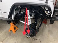
I haven’t even cycled the suspension and I’ve identified a few problems with the orientation of the lower shock mount I’ll need to address before I can. First, the way the mid-arms cycle the diff create a subtle clearance issue for the coil spring and the coil bucket at ride height.

03bd7b73d76b12f5acdb57abfb01c347.jpg

Second, the shock sits almost perpendicular to the ground in all regards at ride height which is ok, but not ideal. I’d prefer to have the coils angled slightly out at the bottom so that when the suspension cycles, they never are angled in. Doing so aids in stability on the trail.

62b9137858cfd468cb0ee86ce01b5c5a.jpg

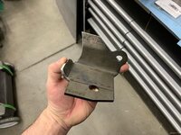
These are lower shock brackets that came with the Evo kit. They’re to convert the stock shock mounts to double sheer. Think I can tweak and use them.

1551d9b206d1e298e28a06a6db3481c4.jpg

Modified the brackets so they’d fit the tube

1f2239bde85b5461a201f761e65635fa.jpg

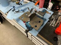
Added a few brakes so they’d tuck up along side the original shock mounts.

8f0dfeed7ac5e6e7b07d91bffd13ef19.jpg

With a little trimming, it now lays up against the knuckle nicely. Now the shock mount will be in triple sheer.

1417d1b7123f33ee158952aa556061c2.jpg

Burned it home with a stack of dimes.

a02516c5381a010e0371d062c33d1a86.jpg
Now the shock can outboard 2” correcting the geometry issue. In its furthest outboard position it’s about 1/2” award fro the caliper. Perfect.

c298908cd7c1cabb5f4fbe9ecbc7604a.jpg
 

Attachments

  • c298908cd7c1cabb5f4fbe9ecbc7604a.jpg
    c298908cd7c1cabb5f4fbe9ecbc7604a.jpg
    28.6 KB · Views: 4
  • a02516c5381a010e0371d062c33d1a86.jpg
    a02516c5381a010e0371d062c33d1a86.jpg
    26.9 KB · Views: 0
  • 1417d1b7123f33ee158952aa556061c2.jpg
    1417d1b7123f33ee158952aa556061c2.jpg
    27.4 KB · Views: 0
  • 8f0dfeed7ac5e6e7b07d91bffd13ef19.jpg
    8f0dfeed7ac5e6e7b07d91bffd13ef19.jpg
    29 KB · Views: 0
  • 1f2239bde85b5461a201f761e65635fa.jpg
    1f2239bde85b5461a201f761e65635fa.jpg
    38.5 KB · Views: 0
  • 1551d9b206d1e298e28a06a6db3481c4.jpg
    1551d9b206d1e298e28a06a6db3481c4.jpg
    20.5 KB · Views: 0
  • 62b9137858cfd468cb0ee86ce01b5c5a.jpg
    62b9137858cfd468cb0ee86ce01b5c5a.jpg
    30.6 KB · Views: 0
  • 03bd7b73d76b12f5acdb57abfb01c347.jpg
    03bd7b73d76b12f5acdb57abfb01c347.jpg
    21.2 KB · Views: 2
Last edited:
To avoid these ads, REGISTER NOW!
OP
L

lilscorpion

Well-known member
Joined
Mar 15, 2010
Messages
3,599
Location
Colorado
With the bolt going through both mounts like that, are you going to run a solid spacer on the side without the shock?

yes, absolutely. Otherwise it will collapse and the bolt will continue to loosen over time repeatedly. I'm out of the material I usually use but it should be here before the weekend.

Matt
 
OP
L

lilscorpion

Well-known member
Joined
Mar 15, 2010
Messages
3,599
Location
Colorado
Where I left off previously I was wrapping up the front end install. Got the suspension and steering in and was moving to the rear. 5 years of usage has the rear-end looking haggard.

IMG_8232.JPEG

Just about every bolt was giving me fits. In many cases, the bolt had rusted to the steel sleeve that runs through the factory polymer bushings.

IMG_8306.JPEG

this condition ***** too. When the polymer bushing sleeve and bolt is that rusty, an impact cant break the bolt free because the bushing defeats the blows of the impact. Totally *****. A few of them ended up like this - more or les I cut the outer housing so I can get inside and grab the sleeve with a set of pliers.

IMG_8287.JPEG

In the end tho, old ones were off, and the new ones were mocked up...

IMG_8302.JPEG
 
OP
L

lilscorpion

Well-known member
Joined
Mar 15, 2010
Messages
3,599
Location
Colorado
With the arms mocked up, the next step was to pull the axle and clean it up. Figured I was past the hard part but rust still wanted to give me fits. These retainer bolts help keep the springs seated when the suspension unloads but they also create a really nice pocket for water to sit anytime there's any moisture. It took some work mostly because there was no good way to get an impact directly on them anywa given the spring fully contains access. LAME.

IMG_8247.JPEG

Ultimately, I ended up more stubborn than the bold and I got it out. Best part is I won't need to use these again since I'm going to coil-overs. Nice up-side. ACOS upper coil mounts/spacers/bump also can be ditched. It's always interesting to remove something you installed years ago and have memories of the install (maybe they're flash-backs) come to you during the process. I recall how difficult I thought it was to get to one of the 5 bolts that attach the assembly to the cross-member. Interestingly enough, it came out with no fight.

IMG_8248.JPEG

Factory calipers and stand-off brackets cant go on without a coating. With the learned tricks from the front calipers, I was able to move along a little more quickly.

IMG_8254.JPEG

I didn't futz around with trying to mask the piston holes this time, went directly to machining a silicone plug to fit perfectly.

IMG_8256.JPEG

Since I'm using silicone plugs, I can use them both for sand blasting and powder. When I used tape before, I had to mask, remove, and remask which took a significant amount of time.

IMG_8263.JPEG

I also took a little time to smooth out the casting a bit with a DA where the flashing was rough or heavy. It's not necessary but it will help improve the finish quality of the coating.

IMG_8265.JPEG

And in the oven they go. Same Red Wheel color as the fronts.

IMG_8271.JPEG

There's an admiration moment on the cooling rack. When they come out, they come out a very deep red due to the temp. As they cool, the color switches to a more vibrant red.

IMG_8279.JPEG

A little hack I learned after doing the fronts. Instead of trying to use existing casting holes in the calipers to hang them during the coating process, I drilled two very small holes and made some custom triangular ended hangers out of wire.

IMG_8288.JPEG

Because the hanger wedges within the hole, it leaves almost no imperfection when removed.

IMG_8289.JPEG
 
OP
L

lilscorpion

Well-known member
Joined
Mar 15, 2010
Messages
3,599
Location
Colorado
When I had the diffs built for my son's jeep, I had them use the exactly same parts as mine so anything I do to mine would directly translate to his down the road fabrication and/or customization-wise. So these plugs will get stored away until I get time to do a run-through of his axles.

IMG_8297.JPEG

Plugs work so much better and faster than tape. Look at the edges of the finish after removed. The seal surface is perfect as well as the internal pocket where the piston rides.

IMG_8296.JPEG

While I was waiting for things to cool, I did a quick run-through of the hardware for the calipers. Noticed that the bleeders were fairly plugged up.

IMG_8323.JPG

Blowing them out didn't get 'em clean but a micro-drill bit did the trick nicely.

IMG_8351.JPEG

5 years is all it took for brand new diffs to get all cruddy. I'm now thinking that I might need to do a complete dis-assemble and inspection every 3 or so years in order to keep things working tops. Cleaned up the threads and then dug into my drawer and found an even smaller drill bit to clean out the top bleeder hole (whatever it's called).

IMG_8428.JPG

Grabbed the thread pitch so I can lean the caliper side of the equation before re-assembly. Here's a pro-tip. Not only can I document this on GJ, but I now have pictures in my album (on my phone) so in the future I know what the bleeder screw pitch is if I get into a bind. I may not always have the necessary tools with me on the trail but my phone always is. Pitch is 1.0 (obviously metric)

IMG_8379.JPG

Measure OD of threads with calipers in MM and round up...so 10mm x 1.0 pitch.

IMG_8393.JPG
 
OP
L

lilscorpion

Well-known member
Joined
Mar 15, 2010
Messages
3,599
Location
Colorado
Now it's just re-assembly. Little grease (elbow and actual) and they're likely now in better working order than when they were assembled at the beginning of their life.

IMG_8442.JPEG

Look a hell of a lot better too.

IMG_8449.JPEG

For now, these need to be set off to the side so I can shift my focus on the main axle assembly.

IMG_8461.JPG
 

Cruzan80

Well-known member
Joined
Jul 22, 2015
Messages
4,158
Location
Denver, CO
What were you making the plugs out of and shaping them with? Casting them, CNC, or...? Maybe I missed it upthread.
 
OP
L

lilscorpion

Well-known member
Joined
Mar 15, 2010
Messages
3,599
Location
Colorado
Before I pull out the rear axle and clean it up, I want to make sure I can get the alignment right with the control arms I built. I'm a little nervous actually because of decisions I made during the machining process. At the time, I was unable to find (or get quickly) a left hand tap so I decided to thread both ends with rights and buy only right Johnny Joints. Those of you who've built control arms before just likely cringed...it was a dumb idea. Not only does a RR arm make it really hard to tighten the jam nuts, they have no micro-adjustment. You can only dial them in to within 1/12 of an inch...one full rev in or out (plus the error factor associated with the variability of where a thread starts it's cut).

IMG_8304.JPEG

And as it turns out, my problem wasn't that I didn't have enough adjustment, it turned out that the arms were too long by just that much.

IMG_8274.JPEG

Easy to fix but doing so did damage the coating.

IMG_8276.JPEG

Back on the vehicle however, now adjustability is a problem. I can get close but I don't have the necessary fine-adjustment to get it right where I want it. So, new arms. If I'm going to do it again, I'm not going to machine them out of DOM tubing, I'm going all in and will machine them out of 1 3/4 7075 Aluminum. Yeah, there's the beef.

IMG_8595.JPEG
 
OP
L

lilscorpion

Well-known member
Joined
Mar 15, 2010
Messages
3,599
Location
Colorado
What were you making the plugs out of and shaping them with? Casting them, CNC, or...? Maybe I missed it upthread.
Nothing fancy (or even appropriate for that matter). I turned them on the lathe using a positive rake insert. It doesn't cut smoothly or well even kinda and, as you can see above, the finish quality *****. But it was just good enough to fit in and seal the hole.
 
OP
L

lilscorpion

Well-known member
Joined
Mar 15, 2010
Messages
3,599
Location
Colorado
Some of my favorite pictures are of aluminum being machined...chewing into the 1 3/4" 7075 rod, I need a pilot so that the larger bits go in centered.

IMG_8639.JPG

No need to step drill, going all in to final dimension. At the right RPM, the drill bit pulls out beautiful chips even in this gummy 7075.

IMG_8685.JPG

And a little chamfer to give a nice lead-in for the tap.

IMG_8700.JPG

Nice edge finish

IMG_8717.JPEG

To make it easier to differentiate the left threads from the right, I'll drop a little grove 1/2" in from the end maybe .100 deep.

IMG_8722.JPEG

All that's left it to power tap one shot (with some cutting oil of course)

IMG_8741.JPG

Ah, and a hack from back when I used to make arms all day long. All I do is mark the tap with the depth so I don't have to think (or more accurately, think less).

IMG_8760.JPEG

a thing of beauty once finished.

IMG_8754.JPEG
 
OP
L

lilscorpion

Well-known member
Joined
Mar 15, 2010
Messages
3,599
Location
Colorado
After running drilling and taping a lot of aluminum, I clean up my taps to make sure they're ready for the next go. Cutting aluminum creates a lot of heat and as a result, drill bits and taps can develop buildup on all friction edges. To get it off, I soak them in Lye. To be clear, it's nasty stuff. Read up on it before trying it at home.

IMG_8813.JPEG

Here's what a quick google finds for a description:

Lye is an alkali chemical- sodium hydroxide, also known as caustic soda. ... Lye can burn the skin and damage the eyes in the dry or wet form. It also releases fumes, when mixed with water, that can harm the lungs. If swallowed, lye will burn the esophagus and can cause death.

Good stuff. I put a few table spoons into a stainless container and then drop the bits in and let them soak for about 30 minutes.

IMG_8814.JPEG

The stuff works awesome at cleaning up tooling tho. Like new.

IMG_8818.JPEG

Final step on the arms is to machine wrench flats in them. To make them all the same, I'll add the flats to the left side. It's a 2 step process, I use a 3 flute end mill to cut the width and then go back and machine a 45 on both sides to give it a smooth finished look.

IMG_8798.JPEG

and the finished profile.

IMG_8804.JPEG
 
OP
L

lilscorpion

Well-known member
Joined
Mar 15, 2010
Messages
3,599
Location
Colorado
Thought I'd pause to answer a question that was bugging me. Exactly how much weight savings will I get with these new spiffy 7075 arms? While the wife was busy doing something else, I did a little comparison in the kitchen. Steel 1/4" wall DOM - 3lbs 14 5/8 oz.

IMG_8585.JPEG

Aluminum Arms 1 lb 9 5/8 oz.

IMG_8586.JPEG

So about 2 3/8 lbs lighter per arm. That's 60% lighter.

Finally, we test all of the threads left and right to make sure we're good before powder.

IMG_8581.JPEG
 

Monza Harry

Well-known member
Joined
Dec 29, 2018
Messages
1,433
Location
Windsor ON
Final step on the arms is to machine wrench flats in them. To make them all the same, I'll add the flats to the left side. It's a 2 step process, I use a 3 flute end mill to cut the width and then go back and machine a 45 on both sides to give it a smooth finished look.

IMG_8798.JPEG
Matt I would suggest you consider a fly cutter like one these:
or:
I have an apparently now discontinued one like above in a 5/8" min. Dia./ 1" max. Dia. that I use the $#!+ out of on my own projects, the companies I have worked for won't buy me replacement inserts they lose! Those are KBC Canada prices so look just a little for less than 1/2 in the US, If you hit up a couple of swap meets with a new tooling section you should be able to grab a 3 Pc. set with a round insert a square core and the 45* one for about $100 US pre Covid smackers. If I were to this purchase over the first one I listed would get a real close look see as it will c'fer the inside of a slot or an overhanging edge in one set up, I have worked a shops with those and they have had myriad of uses worth your consideration especially for wrench flats. Harry

Here is that set on Amazon Canada:
Sorry our search engines tend to select .ca (Canada) first so the US set should be even cheaper
Sorry I had a case of premature hot-linking! LOL!
 
OP
L

lilscorpion

Well-known member
Joined
Mar 15, 2010
Messages
3,599
Location
Colorado
Matt I would suggest you consider a fly cutter like one these:
or:
I have an apparently now discontinued one like above in a 5/8" min. Dia./ 1" max. Dia. that I use the $#!+ out of on my own projects, the companies I have worked for won't buy me replacement inserts they lose! Those are KBC Canada prices so look just a little for less than 1/2 in the US, If you hit up a couple of swap meets with a new tooling section you should be able to grab a 3 Pc. set with a round insert a square core and the 45* one for about $100 US pre Covid smackers. If I were to this purchase over the first one I listed would get a real close look see as it will c'fer the inside of a slot or an overhanging edge in one set up, I have worked a shops with those and they have had myriad of uses worth your consideration especially for wrench flats. Harry

Here is that set on Amazon Canada:
Sorry our search engines tend to select .ca (Canada) first so the US set should be even cheaper
Sorry I had a case of premature hot-linking! LOL!
I have a bunch of different chamfer mills and tooling, I tend to use the thing that's closest and easiest (which quite frequently also ends up to be the one closest). On the lathe I do like to use a internal threading bar too...probably because I almost never use it for internal threads. The one I used is actually dummy proof too because it won't cut much deeper than you see unless you lay into it fairly hard.

...and on the chance you didn't notice, the chuck is stopped and the tool is spinning. I had the chamfer tool chucked in a cordless drill. Faster (or non-existent) tool change. ;)
 
Last edited:
OP
L

lilscorpion

Well-known member
Joined
Mar 15, 2010
Messages
3,599
Location
Colorado
With the tools out, I also knocked out the tie rod and drag link...the ends are way beefy 2 1/2 ton units.

1FE6607F-B448-4CB5-ACAF-08B2229F7295.jpg

pulling some measurements. In this case, the ends are so long, the tie-rod doesn't really need to be.

IMG_8528.JPEG

Parts are starting to pile up..

IMG_8793.JPEG

Drag Link will fit in the oven just barely on the angle, Tie Rod is too long. Gonna need a bigger oven.

IMG_8806.JPEG
 
Last edited:
To avoid these ads, REGISTER NOW!

JonBoehman

Well-known member
Joined
Oct 7, 2011
Messages
364
Location
Philpot, Ky
Man, how have I missed so much on this thread? Was the progress in another post? Great work on the jeep by the way. Hoping to get mine in the shop for some upgrades as soon as i get done gathering materials.
 
OP
L

lilscorpion

Well-known member
Joined
Mar 15, 2010
Messages
3,599
Location
Colorado
Great progress Matt. Love seeing the Jeep's suspension come together. I'm jealous.
Thanks Mike. It's coming a long nicely now but there's still so much work left to do!
Man, how have I missed so much on this thread? Was the progress in another post? Great work on the jeep by the way. Hoping to get mine in the shop for some upgrades as soon as i get done gathering materials.
I did do an update on my Son's jeep in another thread -> see my Tooling(Re)Organization thread in my signature. Other than that, there's been not much to update. I'm getting after it now so that my son and I can wheel this spring when the mountains thaw out. Gotta hustle.
 

csp

Well-known member
Joined
Mar 23, 2010
Messages
5,719
Location
Franktown, CO
Nice work Matt, as usual.

You wouldn't happen to know anyone with bent/broken JK D44 rear shafts by chance? I have an empty housing and want broken/bent shafts to bolt on to the ends of the housing just for mockup purposes. I'm putting a CJ6 body on a shortened JK frame and suspension. Having tires and wheels mounted to junk axles would sure make tub placement easier to visualize.
 
OP
L

lilscorpion

Well-known member
Joined
Mar 15, 2010
Messages
3,599
Location
Colorado
This is going to be an interesting segway into a parallel project which is necessary in order to finish the jeep...remember I have a Tie-Rod that won't fit in my oven so I'm unable to powder coat it. Super annoying to run aground during a build like this but it is what it is, have welder, can solve.

About a year ago I was doing some upgrades to my air system for my sand blast cabinet which required I remove my oven from it's cabinet. When I put it back, I was in a hurry and wired it up wrong...up in smoke. I was able to find another one just like it locally for like $100. No biggie. The fried one went out back to be disposed of when I get my next roll-off dumpster sometime this year. I've done some crusin around the inter-webs and found that some guys are taking double in-wall ovens, cut out the middle part, and make that double into one bigger/larger oven so you can coat bigger parts. The math don't like, I need an oven that can coat a 46-inch tall part and a double oven will only get me into the mid 36-inch-ish range. I need a tripple oven. Since I have the fried one on the side of the house, all I need is a double.

I didn't get a lot of pics of the first steps on this one, I'm trying to move kinda fast...I located a double oven in my area and bought it for about $125. Last night I started dis-assembling it and the fried single oven. It went a lot faster than I had anticipated. In almost no time, I had it down to the skin, made some strategic cuts, stacked it up, and screwed it back together.

IMG_9167.JPEG

It's far from rocket science. All I'm doing is using some of the scrap pieces to act as braces between the upper, mid, and lower assemblies. They're tied together with nothing more than sheet metal screws. Eventually I'll seal the assembly with high temp caulk to to help keep the heat on the inside.

IMG_9168-1.JPEG

Tiny little tweaks/taps with a body hammer, a few little welds to permanently fuse the pieces together, and it's now just one big oven with fully functioning grooves down the entire inside which enables racking to be added anywhere. The sheet metal screws ill have to be replaced with rivets tho, they do interfere with the racking in just those specific grooves. Not a now thing tho.

IMG_9169.JPEG

Feelin' really good with myself, I then shifted focus on the doors. Figuring out how to turn 3 doors into a single door is likely where the most work is at. Gonna have to think about it a bit and take some measurements. Maybe I'll have a great idea.

65438480687__DE40B658-DA14-4B64-99CC-801E4307EC35.JPEG
 
OP
L

lilscorpion

Well-known member
Joined
Mar 15, 2010
Messages
3,599
Location
Colorado
Arrived yesterday

D685EDEA-0C4A-47B5-ADDC-A736EBADDBE0.jpeg

the Power Tank mounting bracket. The Power Tank is a CO2 tank that off-roaders carry in their rig so they can add air to their tires and/or run tools on the side of the road. The bracket comes in 2 variants - black and in shiny aluminum. I wanted something custom so the shiny aluminum is the easiest starting point.

50DB2E06-D665-4695-9F72-A6D9B704F6A4.jpeg

and since I can’t leave nothing alone, I started to disassemble it. Removed the rivets that hold the straps on

33715827-CA13-441B-839A-7D8D8EA10C9B.jpeg
BF9C2703-22B2-47FC-A7CA-B9DDF20C5432.jpeg

Pulled off the logo/sticker gonna need that later.

236C2F9A-AC7C-43CC-9677-05EDC8C82500.jpeg

Sand blasted it so it had a nice etch for coating.


1BF16D4A-0432-4BE8-ACB8-A274BF8BAFF9.jpeg

ready for coating

C292BE26-75CF-40A9-BC94-E1746D461EE4.jpeg
 
Last edited:
OP
L

lilscorpion

Well-known member
Joined
Mar 15, 2010
Messages
3,599
Location
Colorado
Coating the bracket with the factory Bright White.

IMG_7804.JPEG

IMG_7809.JPEG

In the oven it goes

IMG_7810.JPEG

About 20-ish minutes later the bracket's got a new shine. 😁

IMG_7812.JPEG

Re-install the tank bumpers/isolators and, of course, the sticker.

IMG_7813.JPEG

Rivet the stainless straps back on.

IMG_7916.JPEG

And just like that - custom.

IMG_7917.JPEG
 
OP
L

lilscorpion

Well-known member
Joined
Mar 15, 2010
Messages
3,599
Location
Colorado
Final assembly - black grip, white regulator guards, matte black tank body, and white mounting bracket. That ought to look good in the back of the jeep.

IMG_7920.JPEG

Anyone looking really close may notice the super charger sitting to the left of the bottle. Soon, very soon. :love:

IMG_7921.JPEG
 
Last edited:
OP
L

lilscorpion

Well-known member
Joined
Mar 15, 2010
Messages
3,599
Location
Colorado
Matt- bracket looks much better powder coated! I missed it.. what’s the tank it holds?
Ah, sorry. It's a CO2 tank that the off-roaders use to fill tires and sometimes run tools on the side of the road. For me it's nothing more than a backup which I carry as a redundant air source to my ARB/Electric on-board air compressor.
 
OP
L

lilscorpion

Well-known member
Joined
Mar 15, 2010
Messages
3,599
Location
Colorado
Also spent the evening coating multiple rounds of bolts, washers, nuts, etc. Wanted to be ready for getting the Jeep on it's new shoes this weekend.

IMG_8557.JPEG

By now you guys are probably getting tired of watching me powder coat every little part. Ain't gonna lie, I'm getting tired of it too but I gotta finish what I started. Yes, every bolt, every nut, every washer. When someone gets under my jeep (however that may occur), between the suspension, brakes, hardware...I want them to say "damn".

IMG_8560.JPEG
 
OP
L

lilscorpion

Well-known member
Joined
Mar 15, 2010
Messages
3,599
Location
Colorado
Yeah, damn. What's super dumb is powered coated fasteners can't survive being tightened with an impact or with 12-point wrenches/sockets. They have to be hand tightened with 6-point wrenches and/or sockets on a ratchet. The price we pay...
 
OP
L

lilscorpion

Well-known member
Joined
Mar 15, 2010
Messages
3,599
Location
Colorado
In order to get the JK back on all 4's I need the tires mounted on the wheels. For those not familiar, beadlocks are used on 4x4's so you can reduce the air in the tire down to a pressure where the footprint of the tire widens so you can get more traction in snow, rocks, sand, etc. What it prevents is the tire from de-beading.

This process is a little tedious but, more than anything, it's a hunched over activity that requires patience. Hunched over activities kill my back and patience isn't something I stock in my shop.

8AA69D43-7D7E-463A-ABFE-AF92B7FB41F1.jpg

Basic hardware. Grade 8 bolts that ultimately get torqued to 24 ft lbs. To get things to seat right, I start at about 15 ft lbs and increment 4 times working in a N, S, E, W pattern (it's the only way I can keep the sequencing right).

IMG_8768.JPEG

Hardest part is getting the bead seated in the the wheel lip. The Bead on these tires are somewhat beefy so I had to work it around and push it in with a screwdriver. These large fender washers helped a lot keep the progress I made stay down in the lip.

IMG_8826.JPEG

Here's a little bit better look. It's a silly game but it's gotta be played.

IMG_8828.JPEG

The glory comes when you get to test fit them. Andrew and I took a break from swapping out the control arms and helped me test fit one. You'll have to wait for the reveal for better pics. Spoiler - looks sweet.

IMG_8887.JPEG
 
Last edited:

Southern83

Well-known member
Joined
Jun 15, 2017
Messages
193
Location
North Carolina
I really like the wheels. I have always said if I went to beadlocks it would be on Hutchinson wheels but I really like the look of those KMC's.
 
OP
L

lilscorpion

Well-known member
Joined
Mar 15, 2010
Messages
3,599
Location
Colorado
I really like the wheels. I have always said if I went to beadlocks it would be on Hutchinson wheels but I really like the look of those KMC's.
Hutchinson’s are really nice. Split wheel design are safer too…well that’s why they have a DOT certification. They were on the list I compared before I went with the methods. At the time I purchased, they were (and maybe still are) on back order.
 

Southern83

Well-known member
Joined
Jun 15, 2017
Messages
193
Location
North Carolina
I haven't looked lately. That's by design, I don't want to have a weak moment. They do not come up used hardly ever. My BIL has them on his LJ and he is talking about selling. I may try to get them if he does part with the Jeep.

Caint wait to see yours on all four.
 

csp

Well-known member
Joined
Mar 23, 2010
Messages
5,719
Location
Franktown, CO
There was a set of 17", 8 on 6.5" Hutchison's that showed up on Roller auction maybe a year ago. They had been labeled poorly and they sold very cheap, like $200 or thereabouts cheap. I was so mad at myself for not setting up an alarm to keep from forgetting about them, but I didn't remember until they had already sold.
 
To avoid these ads, REGISTER NOW!
Top Bottom