To avoid these ads, REGISTER NOW!

Motorcycle Build

Ohmthis

Well-known member
Joined
Jan 20, 2013
Messages
3,000
Location
Outside of Louisville KY
Wow! Quite the adventure. Great job on the renovation of the garage. I’d have to do that before ever putting a tool in. Otherwise I’d start using the garage and the renovation would never get done. I’m also interested in the bike build. Can’t wait for that to continue.
 
To avoid these ads, REGISTER NOW!
OP
I

indisguise

Well-known member
Joined
Sep 15, 2019
Messages
103
Location
Rust Belt....
Its been bitterly cold here and garage time has been scarce... However I did brave the elements to fault find the power feed and adjust the lathe...

I had previously mentioned that the bearing caps were possibly damaged, and promptly ordered some from eBay. While waiting for delivery I "donned" the glasses and carefully inspected the caps (a smarter person would have done this prior). I noticed a spec of junk on the large cap which promptly got removed. I then re-inserted the caps and set the bearing endplay to 2 thou (for starters), with each shim being no more than .001 difference. After tightening the end caps it ran better than ever. With barely zero heat generated at the cap, the end play was reduced to just over .001 with the slightest amount of heat after running for 5 minutes flat out. The manual specifies between .0007 and .001 for 10L...for an old machine this seems close enough.

So for those paying close attention to these ramblings, You might remember I have purchased:
  1. Brand new spindle bearings.
  2. Second spindle with bearings
  3. Three separate bearing caps LOL
In all honesty all that was needed was the new bearings since the old ones were run without expanders and trashed. Lesson learnt here :)

Anyway onto the Servo 140 power X feed.

After inspecting the unit I found:
  1. Sliced end stop wire.
  2. Sliced power cable.
  3. "Dry joint" on one of circuit board solder connections.
After fixing all of this....read assembling and diss-assembling many times....It was still operating in a really "clunky" fashion... After one last strip down the issue was isolated to the reverse tumbler as shown below. The plastic piece is cracked where it joins the shaft. This was causing some really odd behavior. Anyway new parts available and I ordered two from HR Machine Repair . I typically always purchase a spare when the shipping is $$$.

B5-E5-D2-CF-CBF3-40-B8-BE36-666-C96-CC8-D7-C.jpg


D6-C31036-92-CE-4666-AFAB-58-F806-FD1-A66.jpg

This should hopefully get fixed....

While I wait for parts I will swap to the VFD install. This is basically the same as I did for the lathe. Nothing overly complicated.

Happy holidays...
 
OP
I

indisguise

Well-known member
Joined
Sep 15, 2019
Messages
103
Location
Rust Belt....
The parts for the power X axis arrived quickly and reinstalling these was quick. I now have a working power feed on the X axis. I just need to install the limit switch. Also I really do need to remove those sheets of plywood. They really cut down on light.

Power-Cross.jpg


On to the VFD installation

This will follow the same path I took on the Lathe VFD..

Lathe.jpg

The first step is to assess the wiring that exists... I decided to reuse the original tumbler to provide forward and reverse.

Here's the original Tumbler.

Tumbler.jpg

Next I rerouted the power feed from the tumbler to the motor...

The ground was relocated into the motor box as shown below . Its important to isolate the t1, t2 and t3 windings while you have this open.

L1 = terminals 1 and 7
L2 = terminals 2 and 8
L3 = terminals 3 and 9

Motor.jpg

The new wiring to the motor and the tumbler.

External-cabling.jpg

Next I need to prepare the wires to attach to the VFD.

Wire-ends.jpg

Then the VFD was installed in a small NEMA enclosure along with the external breaker and contactor. The 230V power arrives at the bottom right of the enclosure. Three feeds go through the breaker. L1, L2 and neutral. The contrator requires 115V energizing circuit and this explains the need for the neutral. The control wires and the L1, L2 and L3 motor connections leave through the bottom left.

VFD-Wiring.jpg

This larger picture better explains the wiring for the external switch:

Inside-Case.jpg

The switch here attaches to the door of the NEMA enclosure and looks like so...

Case.jpg

I still need to add some ventilation holes...but the Mill works!!! I just need to program the VFD to use the external switch.

Anyway that's all for today...but I'm stoked to see this beast running.
 
OP
I

indisguise

Well-known member
Joined
Sep 15, 2019
Messages
103
Location
Rust Belt....
does the vfd need to be sized to the horse power of the motor ?
Apparently the VFD rating should be larger than the motor. For example, use a 3HP VFD for a 2HP motor.

The observant readers will notice that I did this for the lathe, however not for this Bridgeport. This VFD was in my "spares" pile....and hence it matches the motor. This may cause me issues. Let's see....

The mill is slowly coming together and after running the mill for a while we have an issue...The bearings and spindle bushing sound trashed.

It looks like I will be tackling these tasks...


And this...


Luckily these guys sell the rebuild kit for this mill... Keep you posted...should be fun :)

This thread is turning into a machine rebuild thread now....I swear I started off attempting to build a motorcycle ROFL.

Happy New Year.
 
OP
I

indisguise

Well-known member
Joined
Sep 15, 2019
Messages
103
Location
Rust Belt....
OK.. we have some Bridgeport progress....

Parts arrived. I ended up ordering the entire top end rebuild kit from H and W....great folks to work with FYI.

Parts.jpg
Then I stripped the mill down per the video's from H and W.

In-Progress.jpg

The disassembled parts....

Pieces.jpg

The first task was to remove the compressed spring from the motor vari-disc.. H and W recommend building a special tool. I was able to leverage the motorcycle lift....

I removed an eyelet from the lift. The hole (left behind) matches a 1/2" threaded rod, which I had on hand.

Bench.jpg

Inserted the 1/2" threaded rod with a spacer on the underside.

bench2.jpg

and Voila...a "make shift" spring compressor. This worked really well.

Bench3.jpg

This motorcycle bench is proving very useful. Having the thick steel top is a game changer.

I noticed my first mistake when ordering the rebuild kit. My vari-disc has the Derlin bushes....therefore another order was placed to H and W.

delrin.jpg

Installing the Derlin bushes was way harder than the simple plastic ones for the spindle.

Bushes.jpg

The glue is almost impossible to remove from your hands....so be warned!!! This is after mineral spirits, fast orange and several attempts of removal.

Glue.jpg

While replacing the brake assembly bearing I noticed several issues. The shoes showed contact, the bearing was loose and you could see the beginnings of a crack. Therefore the piece below was replaced.

Brake.jpg

After this things progressed really quickly.

Final.jpg

The mill is now super quiet and runs exceptionally well. Pleased to have this done.

The bone yard of old parts was pretty impressive.

BoneYard.jpg


The issues found during strip down were:
  1. Three trashed bearings.
  2. All plastic sleeve bearings worn.
  3. One broken machine screw holding on the speed Hi Lo selector.
  4. No fasteners holding on the top bearing cap.
  5. Trashed bearing housing for the brake hub.
  6. Little grease in the bull gears.
  7. Cracked motor belt.
If you attempt this rebuild I would pay a visit to the H and W YouTube channel and subscribe. Having this available was a game changer.

Hopefully this is the end of the machine rebuilds......now let's move onto the Bike Build :)
 
OP
I

indisguise

Well-known member
Joined
Sep 15, 2019
Messages
103
Location
Rust Belt....
This update is a mixed bag of content...

First the Mill. After spending $600 on the head bearings, I found myself lacking funds to purchase the vice I was after. Originally I planned to purchase a Glacern Vice, however the $600+ needed was now $350 due the repairs mentioned previously. I would love a Kurt, however the new DX6's have received some bad press and the ebay shipping on the older D688's meant the barrier to entry was high.

A budget of $350 for a vice is really fairly small and this immediately removes US made vices. Therefore I moved to tools made in Taiwan. My previous experiences with Taiwanese tools is good.

The first found was:

Shars 690v

This totaled around $430 shipped, but was out of stock :(

Then I looked at the Haas site and found this, which was again just out of budget...

HAAS

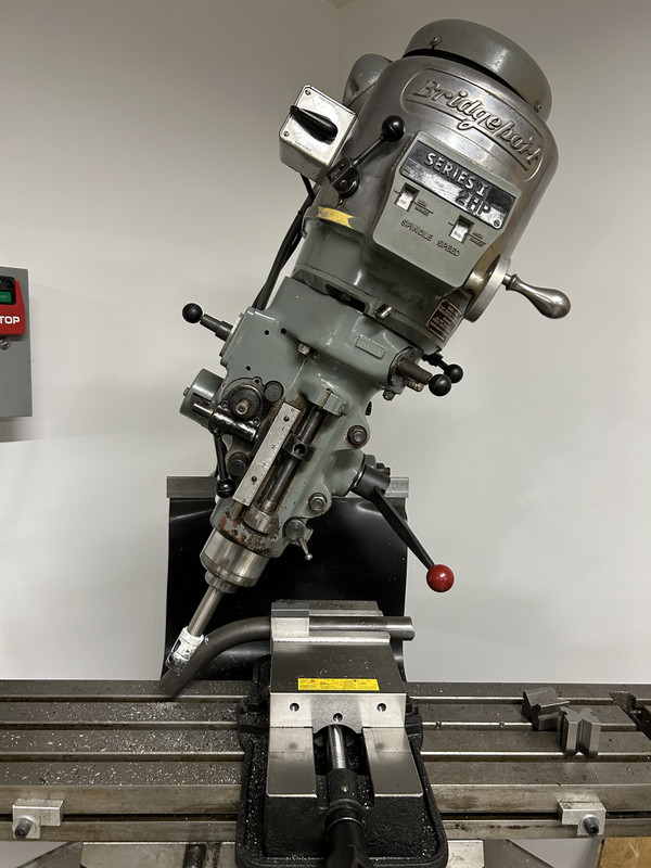
After this I stumbled around youtube and watched a million videos on vices made in China... until I stumbled upon "This Old Tony's" review of an Eisen vice (over 6 years ago). While he found issues with the vice, his review remained positive.

Eisen Vice

With shipping the vice was $350. I decided the risk was acceptable and pulled the trigger. It arrived quickly and the quality was far better than expected. I placed it on the mill and measured the tolerances and it will easily work of my needs.

vertex.jpg

After this I was able to start machining my first project. Note at this point I have never actually touched a mill before!

The project is an adjustable mount for holding frame tubes. I will share the design in a later thread as it progresses.

First the layout stage with plenty of math. Then the design was transposed to the AL.

project.jpg


Then onto the milling. I slowly felt "at home" at the mill after fumbling around with controls, speeds and feeds. Initially I broke two end mills until I began to appreciate what's possible and what's not.

The first operation was acceptable if a little rough:

project2.jpg

However things quickly progressed and the finish on the second operation was far better.

project3.jpg

Then it was time to pause while I assessed what tooling would be needed to complete this project. I will return to this... Tooling = $$ and hence a need to save a little...

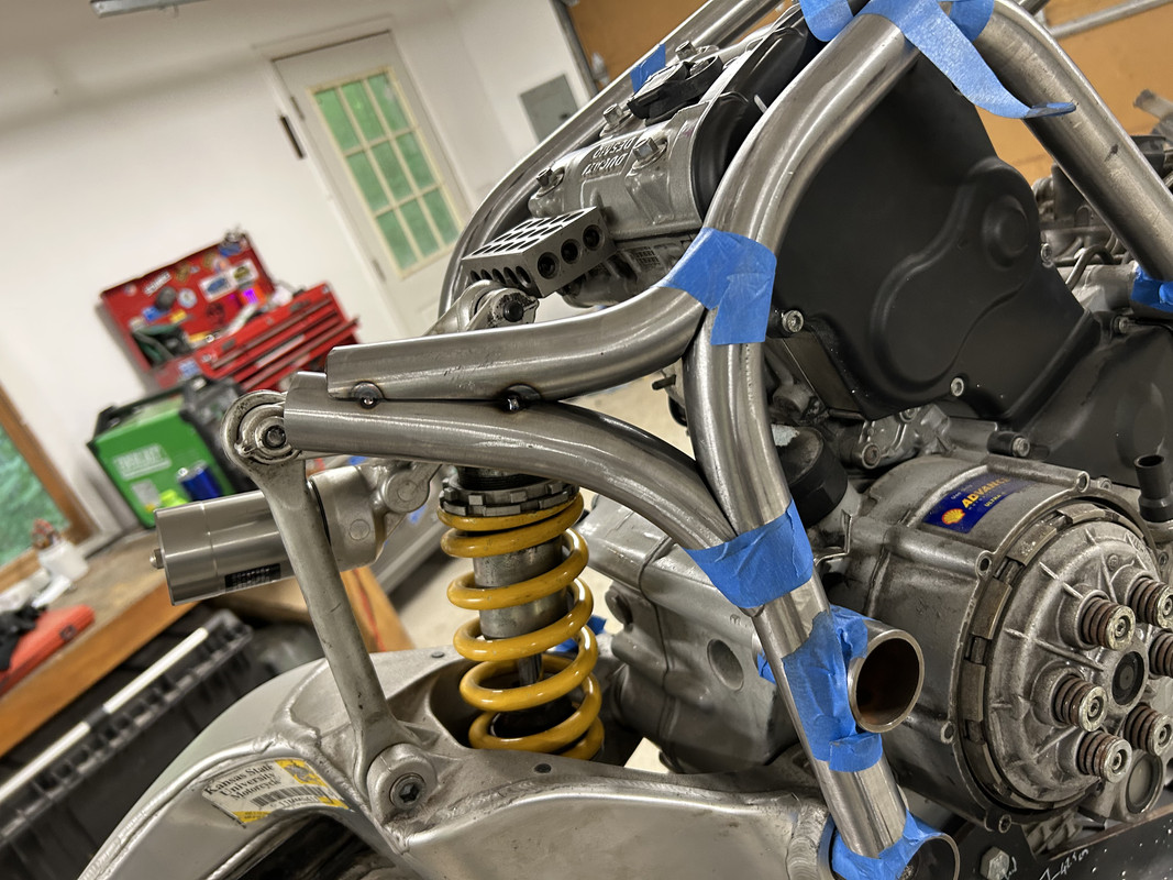
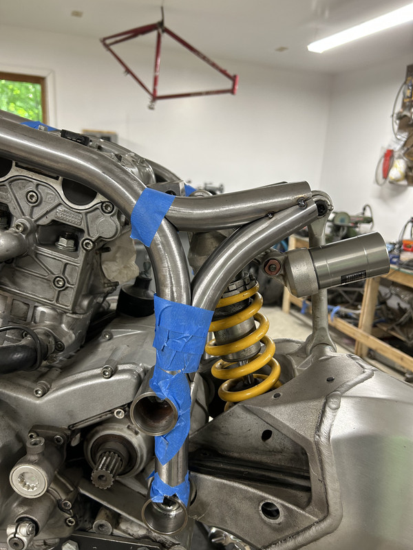
Welding: I previously mentioned that my welding is not going well. Therefore I decided to bite the bullet and replace several torch pieces in a effort to fix the issue....clearly blaming my tools ;) The welder is an Everlast EXT210 TIG and usually works extremely well. I'm not the best welder (read fairly new) however I really want to improve my skills in this department prior to welding the frame. Therefore PLENTY of practice will be required along with some failure analysis :). Should be fun...

After rebuilding the torch, I collected an assortment of 4130 from the pile and decided to practice...First the tubes were coped..

Tubes1.jpg


Then onto the first weld:

It was cold in places and and hot in others. This is all down to torch angle. You can also see craters at the end of the weld, indicating I dumped the foot pedal as I finished :(. You will also notice inconsistent width of the weld pool...this will come with practice.
.tubes2.jpg

After many tubes later things started to improve. I'm still cold in places while being hot in others...but i see progress. The out of focus top weld shows a common issue...the incorrect torch angle is dumping too much heat creating a dull weld with a large HAZ (Heat affected zone). To make things tougher I created difficult welding positions which really helped me focus on the weld pool. Towards the end things started to show progress. Still a LONG way to go...but I'm on the right path.

tubes3.jpg

Anyway that's all for now folks....This adventure will be a LONG one......
 

jake28

Well-known member
Joined
Aug 28, 2018
Messages
481
Location
SF, CA
Kudos on all fronts and for digging straight in with new tools and processes.

Re: mill, DM me your address and I’ll send you some end mills, I have a lifetime’s supply. If in doubt, higher speed, lower feed rate. The opposite can get you into trouble quickly.

Re: welding, you’re on the right track. Since you seem to like jumping right in, it might grind your gears to pause and practice on flat stock. Getting the fundamentals down on basic flat stock and t joints saved me a lot of headaches when I ran into the limits of my skill and experience. https://weldmetalsonline.com/collections/flat-metal-coupons is a great way to get clean, and prepped material right to your door for less than the cost of a can of acetone.

JM
 

Monza Harry

Well-known member
Joined
Dec 29, 2018
Messages
1,433
Location
Windsor ON
That seems like a good looking Vise! I bought a Chinese one from CME just across the river in a Detroit Suburb so basically local (~20 Miles) for less than 1/2 price of the steel required to build one like it (I was "gunna" no really) so if something isn't to my liking, I'll just regrind it, it was expected with the build it plan anyway.
I bought the 6" (it has gone up about $90 US [$130 Can $] since I bought, but so has EVERYTING ELSE!!!!):
From:https://cme-tools.com/
And as stated above, way to go just jumping in there! When you decide to take a tiny piece of steel and push it through a bigger piece of steel, something is going to give eventually, [cutter failure or part launches], so don't beat yourself up, at least once every week or two one of us breaks something or has to help someone else with a destroyed cutting tool, and our Rookies where I am currently are about 15 years of daily practice! Your attitude towards metal cutting and your welding are an excellent place to start from! (y) Harry
 
OP
I

indisguise

Well-known member
Joined
Sep 15, 2019
Messages
103
Location
Rust Belt....
So here's some details on the machining work undertaken in the previous thread.

Previously I was using a myriad of tubes and clamps to keep the bent frame pieces in place. This worked, but was extremely cumbersome as seen here:

3-C0285-E3-64-D2-4630-8-EB8-B0448761-EB3-C.jpg


I really needed a way to keep both the left and right tubes parallel while also removing the chance of me getting skewered by the tubes. Since a milling machine joined the foray, I decided to prototype a better mount. Yes another side project....

After testing a few "new to me" machining operations...yes those holes are far too close together...Noob.
Machining.jpg

which ended up with this..

Complete.jpg

This one is pretty "rough and ready", however I really wanted to see if the concept would work....and it does... This support is highly configurable and and can orientated to wherever the tubes are. Win!

In-use.jpg
Now I have the ability to hold the tube parallel and in place. This is so much easier and allows to me to fine tune the mounting points seen here:

align1.jpg

The mounts seen here, along with all the tubes are all new.....yes it was all re-done. The mounts have now been properly machined. During these trials and tribulations I was failing to machine pieces to existing tooling, I was instead worrying about esthetics. While esthetics are important, it was causing all sorts for grief.... Therefore mounts were machined to 1.5" rather than 1.4" which allows me to use existing hole saws and sanding drums.

mount.jpg
**Note to self...watch my speeds and feeds with 4130 on the mill ;)

Anyway that's all folks......
 

jake28

Well-known member
Joined
Aug 28, 2018
Messages
481
Location
SF, CA
Great progress; keep chugging along.
Figuring out the limitations of your tooling, and when to go along with it and when to work harder to get around the constraint, is a really important lesson.
 
OP
I

indisguise

Well-known member
Joined
Sep 15, 2019
Messages
103
Location
Rust Belt....
The first frame support seemed to work remarkably well......So I decided to build another for the top tubes. This support was slightly harder due to the head tube obstructing access. Therefore a slight design change was in order.

First I designed a mount to clear the head tube....This provided some interesting welding lessons when dealing with thin walled tubing attached to thick steel bungs...It came out ok...a little cold in areas but very serviceable to hold a few tubes....

Mount1.jpg

Next I needed a mounting plate. This is incredibly quick work due to the Bridgeport. I can't explain how fantastic it is to have the tools you need. It also provides a chance to learn on the job...

mount2.jpg
This was promptly welded in place:

mount3.jpg
Then a quick test mount to see how the tolerances looked...

mount4.jpg

If I'm honest, the mount is on the tight side, however it works....

I then needed to build the fixture bar to actually hold the frame. I previously used AL for this and it worked well, if a little overbuilt. Therefore I raided the scrap pile and used what I had....Again the Bridgeport was a life saver here too...

mount5.jpg

Here is the mount (missing the tube clamp since I'm out of bolts :( hence the zip tie).

Frame1.jpg

You may notice that the top tube is completely new (and still missing the middle mount)...and you may ask why? Well, previously I stated that I was not entirely happy with the width of the frame where my inner thigh would be when riding. I also wanted the frame to follow the angle of top cylinder head. The picture below highlights the issue. What you can't see is the 1" gap between the front of the head and the top tube...

15-FD6-BBD-0-BE2-4-DE5-8661-D3-BB8-DDA90-DD.jpg

The new design cuts this distance to less than a 1/4" for neatness and the overall design is more pleasing to my eye.
Frame2.jpg
Anyway that's all folks...
 

jake28

Well-known member
Joined
Aug 28, 2018
Messages
481
Location
SF, CA
Resource tip: look up Julian Farnam, he is an absolute wizard of Moto frame design and fabrication. Send him some pics and I’m sure he’d be happy to share some insight.
 
OP
I

indisguise

Well-known member
Joined
Sep 15, 2019
Messages
103
Location
Rust Belt....
Updates have been slow recently however the project is still moving along at a "snails pace".

Tooling update

Tube notching is a difficult art to master and TBH this area has proved troublesome. Recently the angles have been more complex and this along with he hard material (4130) have caused all sorts of issues. My current set up is a trusty JD2 NotchMaster:

Wrist-breaker.jpg

This device recently acquired a new name, "The Wrist breaker". This innocent looking tool will attempt to break you wrist the moment the hole saw looses a tooth. I run this thing pretty slowly and it still bucks like a rodeo horse. Therefore in an attempt to reach old age I'm changing the game.

The solution: some machined arbors that hold hole saws. This was a fun little project utilizing the lathe..

Wrist2.jpg
Note to self: Try to finish the metal with emery cloth before removing it....

Anyway I built several of these. They mount to the Mill using the standard collets.

wrist3.jpg

This one simple change was transformational to my workflow. Its so much easier to set the correct angle by mounting the tube in a block. The accuracy is "night and day" compared with the NotchMaster and my wrists remain in tact! Huge win here folks.

Bike frame update

Not a huge update, however progress is being made. The general look of the frame is slowly coming together and so far I'm pretty pleased.
Frame1.jpgFrame2.jpg

The next job is to build all the cross bracing along with the rear shock mount. However I'm probably going to tack weld what I have here before moving on.

The tolerances are still fairly good..not bicycle build quality but not terrible.

Frame3.jpg

Onwards......with two functional wrists!!!
 

Trapps

ALLIANCE MEMBER
Joined
Feb 10, 2017
Messages
1,992
Location
The Detroit Zoo
Not sure how I missed this thread. However, as a fellow rust belt dweller, fan of all things from Borno Panigale and a basic motorcycle nerd, I dig your work and thread!

Watching now, as creepy as that sounds.

Not sure where in Indiana you're at but May 7th is the All Clubs Day in Stockbridge, MI., bout an hour north of the Indiana border. BSAs, Nortons, Triumphs, AJSs (plus Germans, Italians, Russians, Japanese and Americans) and all manner of two wheeled examples, from boring and mundane to truly special, can be seen.

:beer:
 
To avoid these ads, REGISTER NOW!

ez-duzit

Well-known member
Joined
Jun 24, 2013
Messages
5,094
Location
Marina del Rey
Thanks @ez-duzit. Let me try one of these. I assume you cut the tube in a band saw and sneak up to the profile using this tool.
Simply cut the tube to length (I use a bandsaw) then clamp it in the milling vise at whatever angle is required, using a pair of V-blocks, and feed it into the proper size roughing end mill until the fishmouth is formed. Makes perfect fits. That is how I built this:

thumbnail.jpg
 

johno

Well-known member
Joined
Oct 16, 2009
Messages
2,418
Location
Southern Ont.
I enjoy this thread, thanks.
I was wondering what's the reason for the new frame, far as I know Duc frames are pretty good.
Is it just something you wanted to do, or some other reason?
 
OP
I

indisguise

Well-known member
Joined
Sep 15, 2019
Messages
103
Location
Rust Belt....
@ez-duzit thanks for the clarification. The work on the boat looks amazing.

@johno the Ducati frames are excellent. This project is more about the journey than the destination. However a life goal of mine has been to be built a vehicle, and a motorcycle seems to align with my hobbies.
 

jjeffries

Well-known member
Joined
Sep 7, 2013
Messages
91
Wow, this is the very definition of a journey. Always great when we can see the misses along the way, not just the victories.

John, in Conn.
 

johno

Well-known member
Joined
Oct 16, 2009
Messages
2,418
Location
Southern Ont.
@ez-duzit thanks for the clarification. The work on the boat looks amazing.

@johno the Ducati frames are excellent. This project is more about the journey than the destination. However a life goal of mine has been to be built a vehicle, and a motorcycle seems to align with my hobbies.

Makes sense to me. I'm building a pre unit Triton myself. Not as ambitious as your build, but the same idea of the build being the thing.
 
OP
I

indisguise

Well-known member
Joined
Sep 15, 2019
Messages
103
Location
Rust Belt....
Things have been busy lately due to house chores... This pushed the motorcycle build to the back burner for a while. However yesterday I got a few hours in the garage to make some progress.

First I needed to tack the frame together. This will allow me to work on the rear suspension. Building the suspension around a non rigid frame just seemed counter intuitive.
To be honest this was a huge milestone. The ability to see the frame as a single piece was a major mojo booster! Note the frame is still missing some of the internal cross bracing, however this can't be added until the rest is welded.

Tacked-frame1.jpg

"Most" of the tack welding was fine. I was concentrating on penetration on the thick tubing and unfortunately caught the edge of the mount in one instance. This will need fixing later down the path.... I was super bummed at first however I'm realizing these things will happen and simple things like this are fixable.

Tacked-frame2.jpg

The coped seams were then taped. This will hopefully keep debris from entering the cleaned joint prior to final welding.

Tacked-frame3.jpg

And here is another angle.

Tacked-frame4.jpg

I was pretty stoked to see this in one piece. I feel like this is a major milestone in the project and I'm pretty happy with the outcome so far.

I looked back on the journey to get this point... Learn how to TIG..built a motorcycle lift....bought machining tools..fixed machining tools...learn't how to use the tools...and then finally worked out how to actually build what I wanted. Its taken "forever and a day" however getting something from your brain into the real world is extremely rewarding. At first I thought this project was just a "Pipe Dream", however breaking the process down into smaller steps turned this dream into reality. There is still a long way to go...but its moving along nicely.

The next steps will be:
  1. Design and build the rear suspension mount. I have drawings to cross reference for this.
  2. Cut and cope the cross bracing for the frame...
  3. Add appropriate gussets where needed (Tony Foale has a good piece on this https://motochassis.com/Articles/Frame.mod/KawaMods.htm)
  4. Then build a jig to hold the frame for final welding.
A quick shout out to @ez-duzit, I utilized the "corn cob" end mill to cope some tubing and holy cow was that soooo much easier and quicker. It literally speeds up the process by 5X and the outcome is far superior. This is why this forum is so great. So much experience in one place!

Anyway folks that's all for now.
 
Last edited:

jake28

Well-known member
Joined
Aug 28, 2018
Messages
481
Location
SF, CA
“A Pipe Dream” would be an excellent retitle for this thread. I think I’d mentioned it previously either in the thread or via DM, but what I love so much about this build is that you are prioritizing doing and trying over planning and worrying. I spent much of the last year of graduate school on a similar quest to build a bicycle, and worked backwards from building a bike frame to a bike jig to learning to CNC to manual machining and basic TIG welding. It’s easy to get caught up in forum posts and internet rabbit holes that would have you believe that in order to build something like this you need the steady hand of a surgeon, timing of a metronome, experience of a NASA engineer, and libido of a stallion, and the only way to avoid definite decapitation is destructive testing and finite element analysis that would leave your project as the pile of tubes that you started with.

I support a local non profit called Girls Garage that has a slogan that has become a life credo: “Fear less, build more.”

And, lest the fanboys of Modena forget, Ducati hadn’t built a motorcycle until 1945. Prior to the war they built gorgeous and utilitarian radios and shavers. They’re first mopeds we’re built on jigs made from scrap trainer rails.

And and, for inspiration, this is a great mini series on John Britten
 
OP
I

indisguise

Well-known member
Joined
Sep 15, 2019
Messages
103
Location
Rust Belt....
It’s easy to get caught up in forum posts and internet rabbit holes that would have you believe that in order to build something like this you need the steady hand of a surgeon, timing of a metronome, experience of a NASA engineer, and libido of a stallion, and the only way to avoid definite decapitation is destructive testing and finite element analysis that would leave your project as the pile of tubes that you started with.

@jake28 you are quite the "wordsmith". I loved this sentence... brilliant.

In an effort to keep things moving I hit the garage this morning....

First thing was to machine some mounts for the rear suspension. These are really simple bungs that need welding into the end of some 4130.
IMG-0237.jpg

Nothing difficult and pretty quick. Then onto the welding, this is where things fell to pieces... The idea was to weld the bungs to the tube with plenty of weld. The weld could then be machined back since another support will sit where the weld is. It was all going fine until the dreaded "spit and fizzle" towards the end of welding one of the tubes... You guessed it. Porosity from contamination. Next time I need to spend longer cleaning.....

IMG-0238.jpg

You can see above where the issues started after machining back the surfaces...SHOOT!

Anyway lesson learned....Luckily these are easy to re-fabricate. It also reminds me that I need many many hours of TIG welding practice before I attempt to weld that frame...

Here's where the mounts attach the rear suspension linkage.

IMG-0240.jpg

Until another day!
 

GeddyT

ALLIANCE MEMBER
Joined
Jun 17, 2015
Messages
1,239
Location
Bellingham, WA
Since you're already on the lathe turning the bungs, could you have just turned the whole part? Face both sides, turn OD, drill, stepped bore. Might be faster than turning, welding, turning.
 
OP
I

indisguise

Well-known member
Joined
Sep 15, 2019
Messages
103
Location
Rust Belt....
Since you're already on the lathe turning the bungs, could you have just turned the whole part? Face both sides, turn OD, drill, stepped bore. Might be faster than turning, welding, turning.
I originally considered this, however I was worried about the ID of the tube being 0.82". Looking back, I think you might be right. A 3/8 boring bar should work for this operation. Let me give this a shot.
 

cannuck

Well-known member
Joined
Nov 30, 2021
Messages
4,592
Location
Rural SK
Another person who can't understand how I missed this thread. Also a former A10 owner (my first bike). lf I ever get rich and retire I would dearly like to build a NorVin (or possibly a Weslake 1000 in Featherbed frame as I have possibility to score an engine). You are both an inspiration and an embarrassment to all who are watching and being humbled by your persistence and rapidly growing skills -not to forget your excellent taste in motorcycles.
 

Kpaige

Well-known member
Joined
Aug 12, 2015
Messages
751
Location
Big Lake Minnesota
Buell Ulysses?
1686809954148.pngHarley-Davidson Sportster base-Buell.jpeg
No it was a 2000 X1 frame. Modified frame to have upper shock instead of under mount. Custom hand formed aluminum tank and seat, 2009 buell Xb swing arm that has the engine oil in it, 2009 forks with custom machined triples and all gears, shifters, and many other parts custom machined. Had all motogadget electronics and a big bore kit.

Not to high jack the op thread if you want to look at everything it took to build go here

 
Last edited:
OP
I

indisguise

Well-known member
Joined
Sep 15, 2019
Messages
103
Location
Rust Belt....
No it was a 2000 X1 frame. Modified frame to have upper shock instead of under mount. Custom hand formed aluminum tank and seat, 2009 buell Xb swing arm that has the engine oil in it, 2009 forks with custom machined triples and all gears, shifters, and many other parts custom machined. Had all motogadget electronics and a big bore kit.

Not to high jack the op thread if you want to look at everything it took to build go here

Really nice build. Thanks for sharing this. The quality of the finish looks amazing. A custom tank is on my list too.....
 
Last edited:
OP
I

indisguise

Well-known member
Joined
Sep 15, 2019
Messages
103
Location
Rust Belt....
I started work on the rear suspension mounts. I noticed that things start to move quicker as my skills improve and the machine count increases. The Bridgeport has been a huge asset! My suggestion to anyone out there is to bite the bullet and get one....

So here is the initial stab at the mounts. Each mount will be intersected by a cylindrical mount and trimmed flush. Therefore I left plenty of material for this purpose.

IMG-0245.jpg


and from the other side...

IMG-0248.jpg


To achieve the extreme angles on the coped tubes required this...

IMG-0246.jpg


Here I used the hole saw to start, then moved to the roughing end mill as mentioned by @ez-duzit. Sadly my end mill lacks reach...

Tilting the head to make these cuts its easy however it does require re-tramming the head once done...

On other news... I noticed the cost of raw 4130 stock has increased considerably. What used to be $30 is now $50 (over the last two years). Therefore I went on eBay to find a cheaper source. I ended up sourcing some rolled round bar billets from H&L for $30 with free shipping.

IMG-0251.jpg

I was somewhat concerned that machining this would be an issue. I was also worried that the specified 1.75" diameter would reduce dramatically once machined round. To my surprise they arrived 6 thou out of round! I was not expecting this.

It also machined nicely with no issue...my cuts were a little hot...but its all good :)

IMG-0254.jpg

So I received roughly 24" of 1.75" sold 4130 bar for $30 shipped. Its hard to beat!

Until next time folks..
 
To avoid these ads, REGISTER NOW!
Top Bottom