86turbodsl
Well-known member
Really cool build. I'm assuming you're already on the mc-chassis email group? I have wanted to do this for a long long time, either build a frame around a Vmax or a Water Buffalo engine with a FFE.


Many will see, few will notice.As a great general contractor once told me “If people won’t see it, then people won’t see it. But you will.”
Great progress, it’s gorgeous.

@jake28 I fear you know me all too well.. The chance of that tube being on the final bike gets slimmer by the second.....And yes.....I will see it even when not looking at the bike....It will haunt my dreamsAs a great general contractor once told me “If people won’t see it, then people won’t see it. But you will.”
Great progress, it’s gorgeous.
")
It is. I have two Ducati 848 EVO single sided swing-arms. I just love how over built these things are. The 916 example looks tiny in comparison.Ducati single sided swingarm?
Yes they are beefy looking but are also not as heavy as they appear. If I could have figured out how to make one an oil tank I would have used one.It is. I have two Ducati 848 EVO single sided swing-arms. I just love how over built these things are. The 916 example looks tiny in comparison.


the Mc-chassis mailing list is literally a mailing list about building motorcycle chassis. Nothing about performance. You might check it out. there are several famous people subbed, including Tony Foale.I do have Tony's wonderful book along with several others on motorcycle dynamics. I don't currently belong to the mailing list since this build is not about performance.
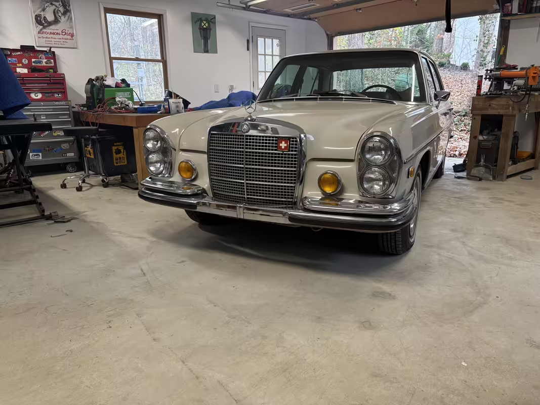
We’ve probably never had it easier to find and see builds from all around the globe, but by the nature of the platform it’s hosted on, this content generally lacks substance. As such, we typically end up getting the highlight reel and the ‘everything is rosy’ perspective, which is rarely the case when modified cars are involved. As anyone who has ever put a spanner to a car will tell you, cars are absolute hardship. If you want an easy life, buy a nice stock car and leave it alone.
But where’s the fun in that?


This is a really good question and one I don't have an answer for. I'm a huge fan of naked bikes, I previously owned an early Ducati Monster which I loved. However there is something aesthetically pleasing about the vintage racer look on a more modern bike. I will probably continue building and just follow my gut. This has been my current mode of operation and the organic approach seems to produce something I could never of imagined prior. No doubt it will cause 5X the work and tons of rework...but that's part of the adventure.Indisguise, cool project! Will this be a naked bike or are fairings planned? It’s be a shame to cover up the artwork of a frame.


Now I get to move onto the welding JIG. This should move a little quicker....


2/10 might be better than my tig welding. And it might be good enough so you can tack everything in preparation of having a pro do the welding. Though I have the welding equipment, I design and fabricate, then have a pro weld it....
Currently my TIG welding is probably about a 2/10. Which is clearly not good enough for welding this frame...
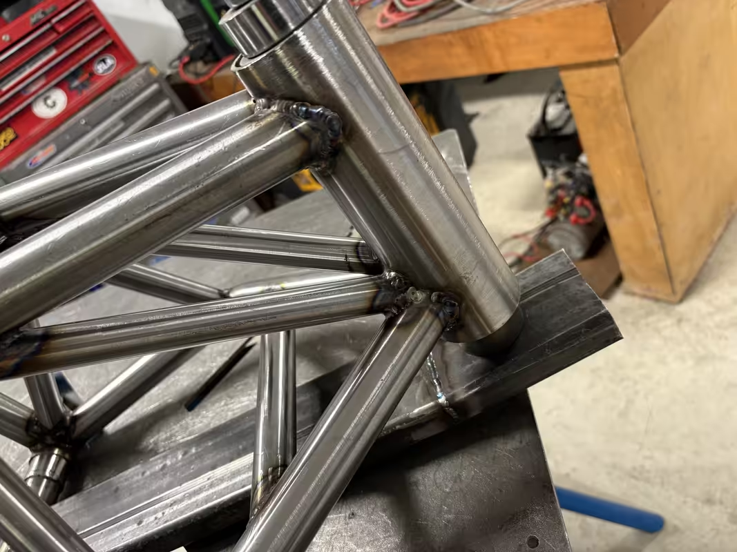
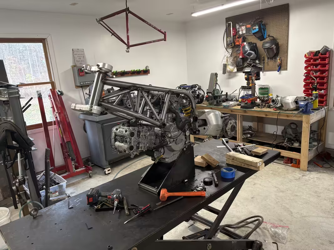
I think you need to look at some actual welding jigs to appreciate just how large and strong they need to be. Even then, there is NO WAY to keep the residual stresses from welding from distorting your finished parts...UNLESS you are prepared to make a very rigid jig, stress relieve it, check, correct and repeat if needed and weld up your parts and stress relieve before coming out of the jig. In reality, hardly anyone is going to do that, but will simply make the jig, verify it's dimensions and geometry, weld the part and accept the net overall inaccuracies of a welded part.Ok.... enough of the old german barges and back to the bike.... I left you with this last time....clearly a lie!
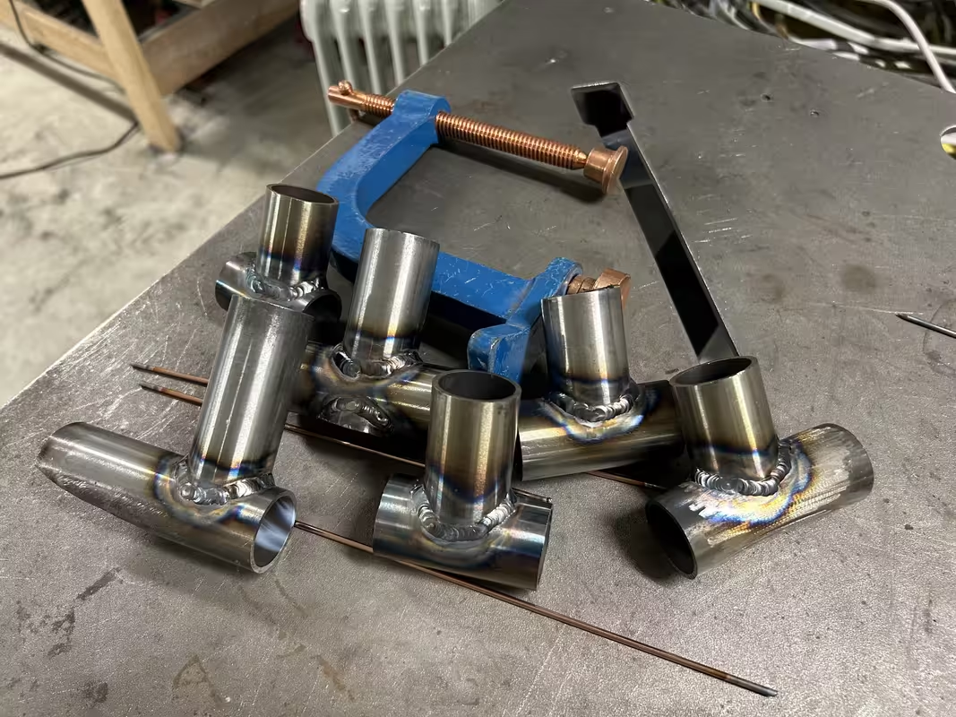
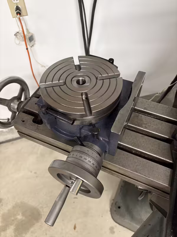
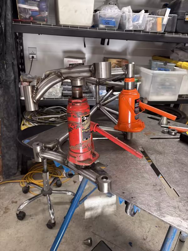
In the background progress was made on the JIG.
First a few cross bars were fabricated..These had bungs turned down on the lathe and then welded.
Then I started attaching stock to link these together...This all needed welding together, which honestly was rather disheartening. Currently my TIG welding is probably about a 2/10. Which is clearly not good enough for welding this frame. You will see later that things never went well and slowly deteriorated. However all of this is part of the adventure....
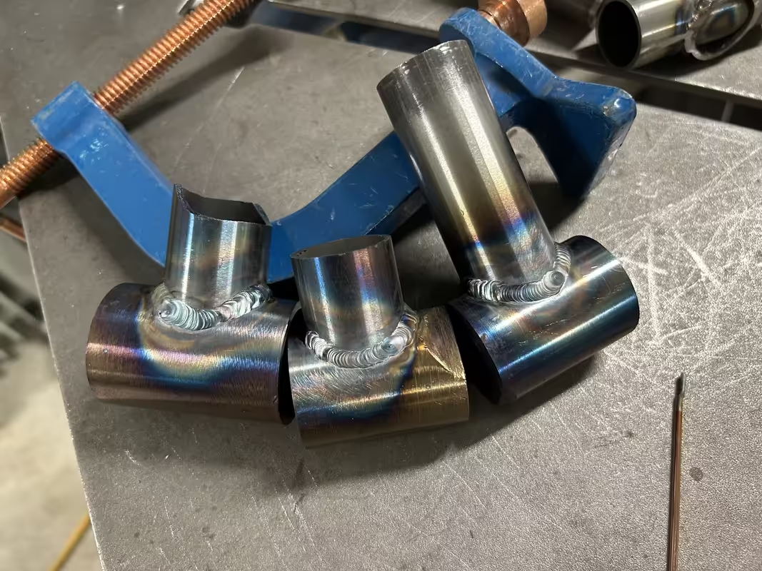
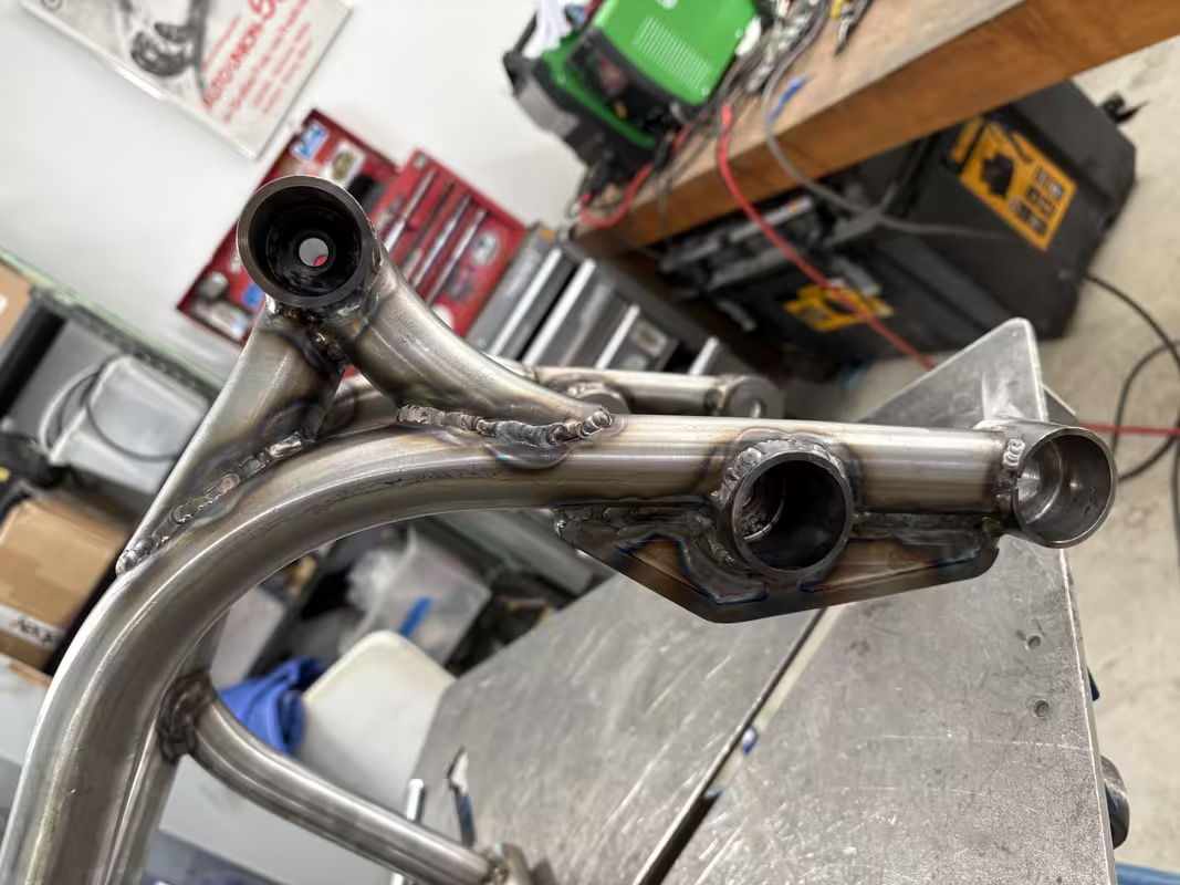
The welding....
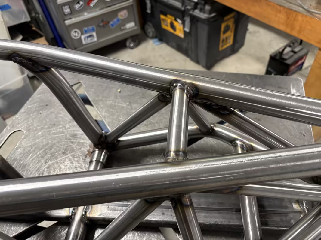
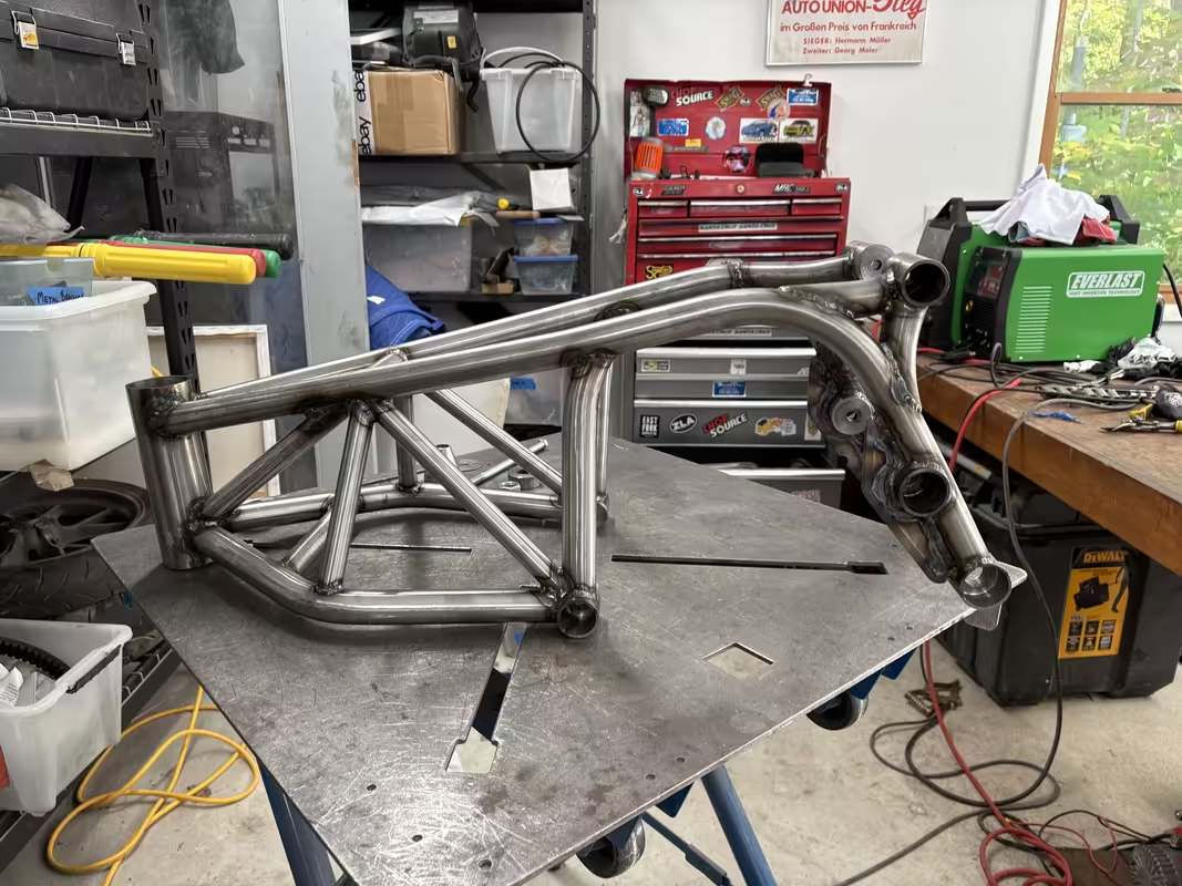
Cold and inconsistent (I was trying really hard not to warp the jig!). . Here is the overall JIG. The last section really is a mess...but will suffice for now and its straight!
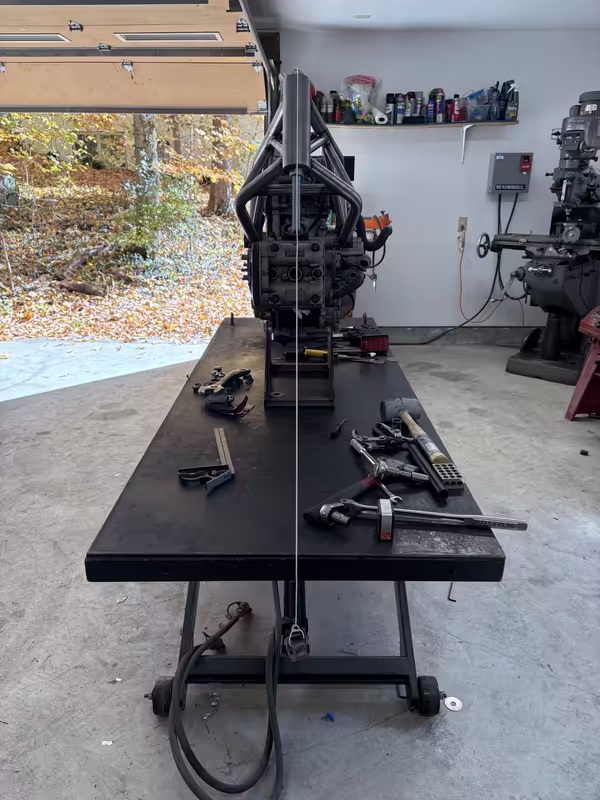
This should stop the majority of the warping and twisting when I eventually weld the frame.
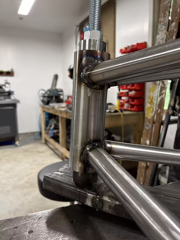
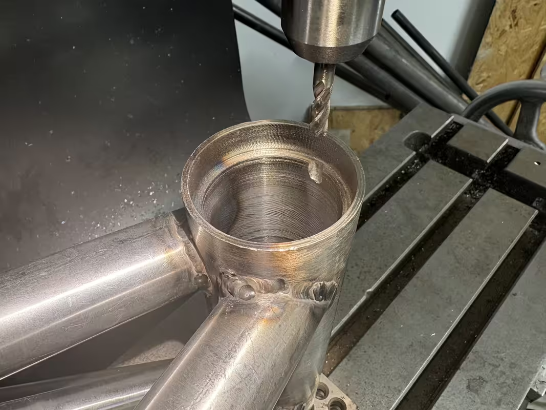
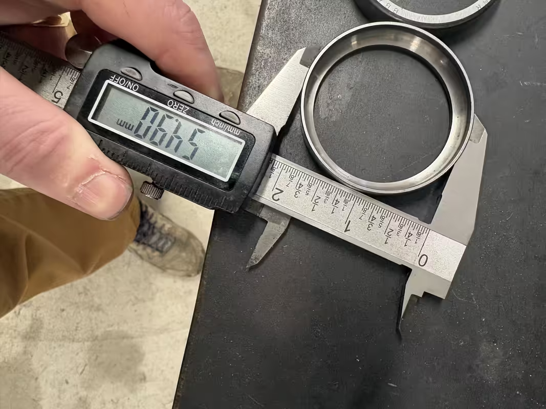
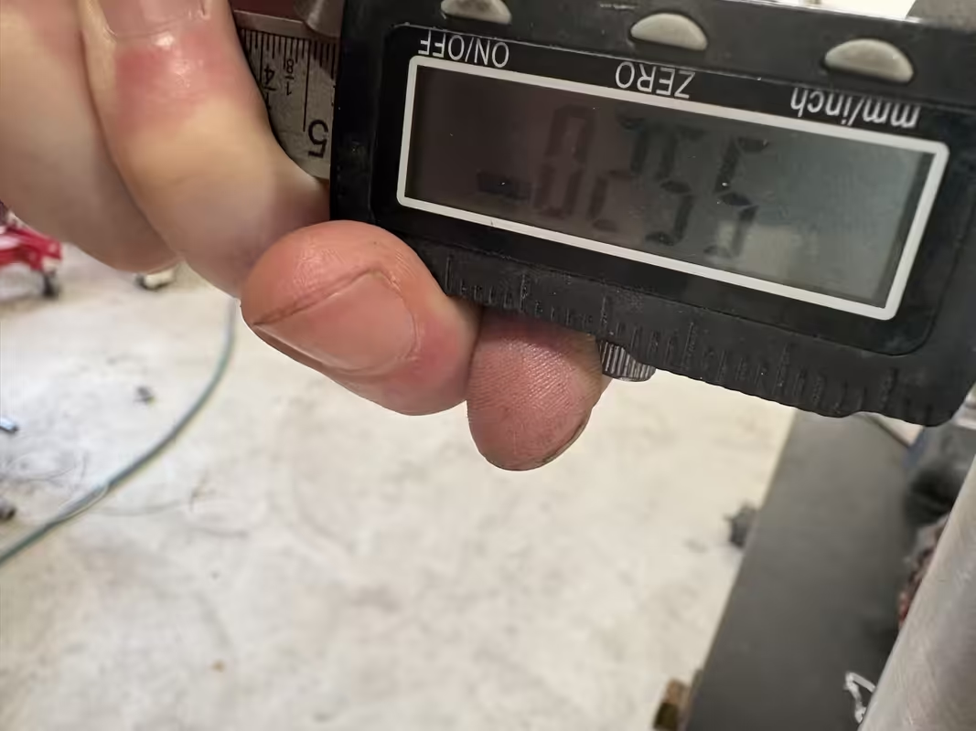
Now the frame was JIG'd I was able to take some reference measurements and noticed the rear left shock mount was 2mm lower than the right. Therefore out with the Dremel...
...
 )
)
@jake28 TBH your recent fantastic updates inspired this post. Your garage is amazing!Delighted to have you back and sharing your progress.
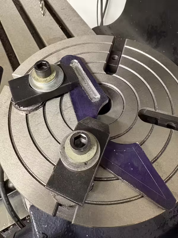
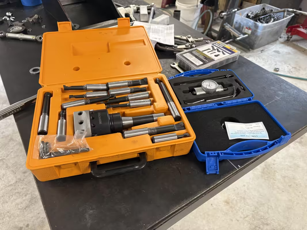
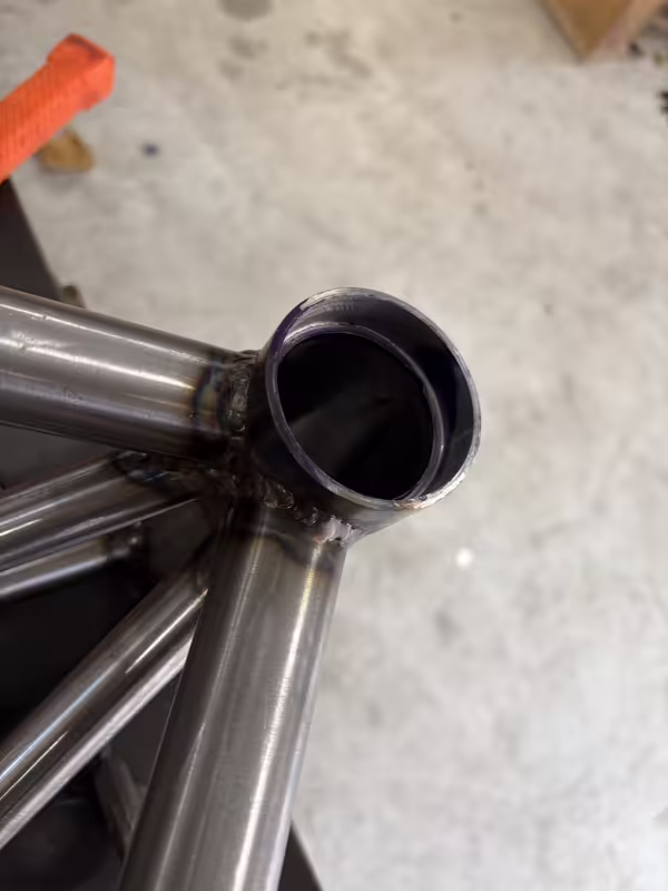
@RoninB4 Its probably 2 and 3. This is my first time trying this with cheap tools...There's a lot of vibration marks in the bore either from 1) too long a boring bar 2) Bad geometry at the cutting edge 3) you were just running the spindle too fast OR 4) a combination of any/all of the 3.
I could not agree more with this quote. The YouTube nation has bred a ton of "experts" who have yet to even strike an arc...The internet is rife with armchair welders and YouTube viewers proclaiming that anything by less than a mirrored rainbow-hued stack of robotic dimes should be a source of shame and direct path to Hades without passing Go.
-Didn't mean to criticize you, just didn't know your experience level. I was awarded a similar "imported" boring head set and found myself rather disappointed using it for the first time. The head is about what one would expect from the COO, functional but nothing to be proud of. The bars themselves are where I found the greater problem as the geometry isn't ground on there like it needs to be. Unless I've got harder material I prefer to use HSS to get a sharper edge without worrying about the fragile nature of carbide with a similar edge. Not knowing your experience level was entirely the basis for my suggestions.@RoninB4 Its probably 2 and 3. This is my first time trying this with cheap tools...