
You are using an out of date browser. It may not display this or other websites correctly.
You should upgrade or use an alternative browser.
You should upgrade or use an alternative browser.
Overseas Jack Rebuild Help Tutorial.
- Thread starter Hiball
- Start date
abrankhalid
New member
- Joined
- Mar 8, 2012
- Messages
- 3
Hey thanks for the input. I already looked through the manual . Unfortunatley, they do not state what valve is located where. They just term the whole unit as "power unit" , so its not really helpful . I am also confused a bit because even when i have the "power unit " out, the ram is still not going in all the way. I am going to post a picture in a few minutes . Maybe that will be more helpful.
Attachments
Last edited:
bczygan
Well-known member
Hey thanks for the input. I already looked through the manual . Unfortunatley, they do not state what valve is located where. They just term the whole unit as "power unit" , so its not really helpful . I am also confused a bit because even when i have the "power unit " out, the ram is still not going in all the way. I am going to post a picture in a few minutes . Maybe that will be more helpful.
Hiball can help you.
You gotta take it completely apart anyway, so just follow this thread. I gotta finish mine too.
Get the big blue plastic box of metric O-rings from Harbor Freight. Sometimes it is on the shelf below the other ones.
Those of you looking to contact or hear from Hiball regarding your jack questions might have to wait a bit. My understanding is that he is dealing with some things that are going to require his attention much more than the forums.
Just want to let you know so that if you message him and he doesn't get back to you, you don't take it as a sign of disinterest on his part.
Just want to let you know so that if you message him and he doesn't get back to you, you don't take it as a sign of disinterest on his part.
abrankhalid
New member
- Joined
- Mar 8, 2012
- Messages
- 3
I understand that. Thanks for letting me know. I am in no hurry.
I also just found this thread. Sure hope hiball is ok / gets things worked out - he sure provided a wealth of info here!
I myself am the owner of a rescued 3 ton MVP superlift. I found the U-cup pretty well deteriorated. Am looking to find a decent price on one - think I need a 25 x 40 x 10. I found one at Blackhawkparts.com, but 17 for the part plus 10 shipping sounds a bit pricey for one seal. Anybody know of something more reasonable?
I myself am the owner of a rescued 3 ton MVP superlift. I found the U-cup pretty well deteriorated. Am looking to find a decent price on one - think I need a 25 x 40 x 10. I found one at Blackhawkparts.com, but 17 for the part plus 10 shipping sounds a bit pricey for one seal. Anybody know of something more reasonable?
I also just found this thread. Sure hope hiball is ok / gets things worked out - he sure provided a wealth of info here!
I myself am the owner of a rescued 3 ton MVP superlift. I found the U-cup pretty well deteriorated. Am looking to find a decent price on one - think I need a 25 x 40 x 10. I found one at Blackhawkparts.com, but 17 for the part plus 10 shipping sounds a bit pricey for one seal. Anybody know of something more reasonable?
HOLY BATMAN.. $27 bucks? LOL.. PM sent.
55dude
Well-known member
don't spend much time here i'm usually on the hamb and just discovered the link. what a great thing to read a tech thread written by someone that knows other than "well i read it..."! i don't have a junk jack yet but alway enjoy reading a well written tech article.
piston farmer
Well-known member
I have a jack that lifts fine and doesnt leak, my big ***** about it is when i release it to lower the car it drops like a ton of bricks most the time and every once in awhile it will lower slowly like i want it to. and suggestions on what to look at for this problem?
More cudos to Hiball! I finished rebuilding my 3 1/2 ton MVP Superlift, and it now works great! I purchased (from Hiball) a new U-cup, and also replaced a worn o-ring at the check valve port (wasn't leaking there, but the o-ring looked like it was in poor shape and I already had the Harbor Freight o-ring assortment). The u-cup measurement seemed to be 40mm x 25mm x 9mm, but apparently 9mm is an odd size. I had a choice of 8mm or 10mm. I picked 8mm, and it seems to work just fine. The 10mm may have fit, but would have been hard to predict without having it in hand. I removed all the hardware I could, except the overload valve (didn't want to mess with the setting) and also one port on the side of the case that I didn't know what was, so I left it alone. There was also a strainer screen I found laying loose inside the oil reservoir (outer section of the big cylinder), Hiball says he finds these loose quite frequently. I had no idea how (or exactly where) to put it back, so I just left it out. I sprayed it out reall well with brake parts cleaner, then used a pressure washer with just water, then used my air compressor to dry it out. Re-assembled, re-filled with jack oil, bled the air out, and it works great. Here's a link to pics, I will add a few more when I get time (with the new u-cup, and a full view of the re-assembled jack). I know MVP is not highly regarded, but I rescued the jack from the street where someone threw it out. So this jack cost me less that $20 for a new u-cup, a quart of jack oil, and some time and effort.
http://www.flickr.com/photos/cocojen/sets/72157629286603784/
http://www.flickr.com/photos/cocojen/sets/72157629286603784/
theoldwizard1
Well-known member
I sure could use some help. My favorite jack quit while I was helping my son with his car. It is a Michelin branded jack ...
Well, I dragged this up because I am working on the exact same jack. My buddy picked it up at an auction cheap. It lifted him (less than 200 lbs) but when he got home it won't a car.
I pulled the hydraulic part out of the jack, drained the tank and removed the tank nut (big cheater on a 24" pipe wrench). I have not taken apart any of the valves. The cup at the bottom of the piston looks okay but it does feel hard. I have not disassembled it yet, but if I have it apart I would like to replace it.
I will probably replace the tank nut seal/o-ring also.
Hiball, do you know the correct parts or do I need to measure ?
Thegratenate
Well-known member
Help,
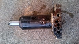
I'm trying to rebuild an old jack all I know about it is that it's heavy and used to be orange. This is what I found when I got it apart.


I haven't pulled the seals out of the pump yet but I don't expect to have much better luck.
Thanks
I'm trying to rebuild an old jack all I know about it is that it's heavy and used to be orange. This is what I found when I got it apart.
I haven't pulled the seals out of the pump yet but I don't expect to have much better luck.
Thanks
Hello Hiball,
Thanks for taking the time to help everyone with their floor jack rebuilds. If you don't mind, I would like to ask some questions about a jack that I recently rebuilt.
The jack is an American Forge and Foundry 200T floor jack. Unlike the other jacks on this thread, it has two pump cylinders. I think one is for the rapid lift and the other is for normal lifting. Prior to the rebuild, the jack would lift a car, but would slowly leak down. During tear down, I could not find any damaged components, though I did replace everything with new seals and o-rings.
Now that I have reassembled the jack, it is still not working correctly. When I pump the handle down, the jack pad raises. As soon as I bring the handle up for the next stroke, the jack pad falls back down. It's like working a see-saw. If I manually pull the jack pad up, it stays raised until I twist the jack handle to release it.
The unit has two overload valves. I have messed with both, even going so far as to turn them all the way in. This has had no effect on the way the jack operates.
Any ideas on what else I can check?
Thanks,
Ed
You have to check the other steel balls that are not the overload valves. The other balls, the small one and the larger one on top of it, are the all important one way valves. These balls have to seal perfectly, specially the larger one, which is the one-way valve holding the weight of the car. (There is another ball that also holds the weight of the car and that is the release valve ball.)
When you raise the handle, the small ball allows the pump piston to **** the oil from the tank but when you push down the handle, this small ball will be pushed into its seat (by the same oil it sucked when raising the handle, venturi effect) and then this oil is redirected to the rear of the ram.
The larger ball allows the oil coming fron the pump piston to go behind the ram but when the oil tries to go back, this large balls closes agains its seat thereby stopping the oil from going back to the tank. As mentioned earlier, since this large ball holds the weight of the car, it has to seal perfectly; any leakeage here will make the lifting arm go down. A strong leak here will cause the seesaw effect you mentioned.
This leakage can be caused by some gummy dirt sticking to the valve seat thereby preventing a perfect seal. Also, small pieces broken off from o-rings from the pump piston itself can lodge in the valve seat. It could also be caused by old balls that have become grey or dark colored. The balls are chromed and they should look bright and shinny. Inspect the balls, there should no rust or pitting on them, any imperfection could cause leaks; replace the balls if this is the case. To inspect the balls get a magnifying glass, or an eye loupe, with at least 5X magnification or more ( more is better). Do not use a regular 2X magnifying glass. As for the dirty seat, use a spray cleaner like carburetor cleaner or brake cleaner and check for any imperfection on the seat surface, specially the bigger ball seat. You will need a small flashlight for this.
To achieve a good seat, the balls are tapped a couple of times against their seat, specially if you are using new balls. You should use either a brass drift or a copper drift or punch to do this. The last resort would be a steel punch. It is just a couple of taps do not pound on them! You will need two punches, one for the small ball and one for the larger ball and the size should be slightly smaller than the ball size. Be carefull not to damage the upper ball seat while tapping the small ball. For this reason the punch should be straight ( no taper) and long. You may have to make these yourself.
When an overload ball leaks, the arm will contact the chassis but, depending on the amount of leakage, the arm may lift a little and then stop or it may not lift at all.
By the way, these one way balls are held against their seats by the oil pressure alone even in cases where there is a very light spring pushing against the bigger ball. This spring either shortens the distance the bigger balls has to move to seal agains its seat or increases the speed of this movement.
If this does not solve the problem, check again the mail seal o-ring and its retainer ( the white plastic ring the o-ring is mounted in.)
Below there is information about valve seats.
http://ohiohydraulic.com/enerpac/E325_catalog/VALVE SEAT CHART INFORMATION.pdf
Last edited:
Any ideas on what else I can check?
Thanks,
Ed
Your Jack is definitely indicating a Valve Issue.. When you rebuilt it did you venture into the Valve(s) or Overload(s)? I suspect its something simple, I doubt you have Seat that is Damaged etc.. Edgar's method of cleaning up a seat is Good, I would rather you first Re-trace your steps before you start hammering on Seats. I suspect something is out of order or you have a contaminate on the seat preventing the ball from seating. Im not familiar with your Jack Model.. If you could post a picture i can probably find you a Breakdown that will aid you with your issue. Also.. If you "Didn't" Tear into the Valves, You will need to.. I suggest you grab a pencil/paper and on any of the Valves that control the overload/speed Changeover you check the amount of Rotations it takes from its current location to completely closed, (Write the rotations down) and then dismantle each one. You can not Properly set the Overload(s) without a Test station. You can use the PM feature to get ahold of me for anything you have issues with. I spend alot of time on the Road and dont always see all the Posts, I have some E-Buddies around here who help out and PM me when i miss a question.
Last edited:
https://www.dsuban.com/website_docs/aff/parts_docs/200T.pdf
I expect your problem lies under the "H30" Cap, This is the Working Valve.
I expect your problem lies under the "H30" Cap, This is the Working Valve.
mdub
Active member
Hi Hiball, Thanks for the great tutorial.
I tore down my Allied jack this weekend and i discovered my ram seal or cup seal has gone bad. I've included a couple pictures below, do you know where i could find a replacement?
Thanks!


I tore down my Allied jack this weekend and i discovered my ram seal or cup seal has gone bad. I've included a couple pictures below, do you know where i could find a replacement?
Thanks!
Hi Hiball, Thanks for the great tutorial.
I tore down my Allied jack this weekend and i discovered my ram seal or cup seal has gone bad. I've included a couple pictures below, do you know where i could find a replacement?
Thanks!
PM Sent...
rodder98
Well-known member
Thanks for this great rebuild article. I love good write ups like this, that have plenty of pictures.
Thanks for this great rebuild article. I love good write ups like this, that have plenty of pictures.
No Problem.. I hate seeing people throw stuff away Needlessly.
Hiball and Edgar:
Thank you for the replies.
Yesterday I found some time to tear back into the jack. The diagram that you sent does not match my jack. It's close, but where the release assembly (H24, H25, H26) goes into the main body, I actually have a second set of valves (H30, H31, H32, H33, H34). There are some parts that are not on my jack (H46, H47, H48). I plan to call American Forge and Foundry on my way home from work today to see if I have a different revision of the jack.
Anyway, I think I have found the issue, though I do not know how to resolve it! On the second set of valves (the ones that install where the release assembly is shown), the smallest check ball was missing. I replaced the check ball with one from the AFF repair kit, and it is still not working. I think the second check ball has disappeared as well. To confirm this, I'll need to pull the pump out of the jack and get it on the work bench.
If the ball is disappearing, where is it going?
Does the jack's behavior make sense if that check ball were missing?
Is the solution to install a larger diameter ball?
Thanks,
Ed
Your Jack is definitely indicating a Valve Issue.. When you rebuilt it did you venture into the Valve(s) or Overload(s)? I suspect its something simple, I doubt you have Seat that is Damaged etc.. Edgar's method of cleaning up a seat is Good, I would rather you first Re-trace your steps before you start hammering on Seats. I suspect something is out of order or you have a contaminate on the seat preventing the ball from seating. Im not familiar with your Jack Model.. If you could post a picture i can probably find you a Breakdown that will aid you with your issue. Also.. If you "Didn't" Tear into the Valves, You will need to.. I suggest you grab a pencil/paper and on any of the Valves that control the overload/speed Changeover you check the amount of Rotations it takes from its current location to completely closed, (Write the rotations down) and then dismantle each one. You can not Properly set the Overload(s) without a Test station. You can use the PM feature to get ahold of me for anything you have issues with. I spend alot of time on the Road and dont always see all the Posts, I have some E-Buddies around here who help out and PM me when i miss a question.
Hiball and Edgar:
Thank you for the replies.
Yesterday I found some time to tear back into the jack. The diagram that you sent does not match my jack. It's close, but where the release assembly (H24, H25, H26) goes into the main body, I actually have a second set of valves (H30, H31, H32, H33, H34). There are some parts that are not on my jack (H46, H47, H48). I plan to call American Forge and Foundry on my way home from work today to see if I have a different revision of the jack.
Anyway, I think I have found the issue, though I do not know how to resolve it! On the second set of valves (the ones that install where the release assembly is shown), the smallest check ball was missing. I replaced the check ball with one from the AFF repair kit, and it is still not working. I think the second check ball has disappeared as well. To confirm this, I'll need to pull the pump out of the jack and get it on the work bench.
If the ball is disappearing, where is it going?
Does the jack's behavior make sense if that check ball were missing?
Is the solution to install a larger diameter ball?
Thanks,
Ed
When you say "Dissapearing" do you mean the Ball is going out of Sight or do you mean its completely going thru the Valve/Past the Seat and you cant extract it with a Magnet? Its hard to see whats going on when your working on a jack that has Oil in it. Sometimes you can get away with blocking the Rear up, so the Oil will run to the opposite end of the Jack. Regardless you need to "Stop" dropping Balls into the holes without being able to extract what you've done. Ive seen instances where those balls can get lodged in the passages and if your adding the Wrong ball to the Wrong Valve it can be Problematic. Maybe some Pictures of what your trying to do, Including what Valve your working on.
windswept4
Member
I can’t thank Hiball enough for his great tutorial.
I did want to add some of my own photos and note that my jack seems to be almost exactly like Binovc’s MVP jack. My jack claims to be "BlackHawk" with an 1,875 Kg capacity # GG920904416. The label says it was made in China and it contains the intitials MVP molded into the pump assembly block. I am virtually certain it is NOT a domestic BlackHawk.
During disassembly all the BB's (check valves) and overload needle valve and spring gushed out with the jack oil. The 2 small BB's measure .25 inch in diameter and the large BB is .35 inch in diameter. A 4th release valve "BB" is inside the release valve cylinder hole. I know this BB is properly located because it never fell out of its cylinder and is still in there.
I have guessed at the location of the parts and have laid them out in a line with each drilled cylinder (see photos below.
I hope the links to "photobucket" work ok.
http://i1104.photobucket.com/albums/h336/windswept4/Hydraulic Floor Jack/IMG_0450.jpg
http://i1104.photobucket.com/albums/h336/windswept4/Hydraulic Floor Jack/IMG_0451.jpg
http://i1104.photobucket.com/albums/h336/windswept4/Hydraulic Floor Jack/IMG_0535.jpg
http://i1104.photobucket.com/albums/h336/windswept4/Hydraulic Floor Jack/IMG_0534.jpg
http://i1104.photobucket.com/albums/h336/windswept4/Hydraulic Floor Jack/IMG_0529.jpg
The release valve drive (a small 1/8 inch half moon drive shaft) turns clockwise to seat a 4th ball (check valve) and counterclockwise to unseat the ball. That ball rests directly under the half moon drive shaft that is driven by torqueing the jack handle shaft clockwise or counter clockwise. That 4th ball is visible in the photo attached below. It never fell out (the 1/2 moon sized washer prevented that 4th ball from falling out).
I’m having trouble finding the sweet spot setting for the release valve (under the star cogs). Mine does not have the traditional needle valve configuration. Mine has a BB for a release valve and i'm not sure how it works. The inner reverse threaded part that fits within the outer release assembly that is attached to the star cog is a mystery to me as to how to re-set and adjust so that the jack will pump up when the cog gears are in one position and release when when the cog gears are rotated.
http://i1104.photobucket.com/albums/h336/windswept4/Hydraulic Floor Jack/IMG_0530.jpg
One of the two smaller BB’s is still a mystery as to its location. That is the one off to the side of the pump block. "Hiball" has speculated that BB may have come out of the side port. It would be interesting to see if Binovc could confirm that underneath the allen bolt on the side of his block sits a BB. He has marked one of his photos with a question as to what is that port used for and I have the same question.
Many thanks in advance for sharing your experience.
Last edited:
The release valve drive (a small 1/8 inch half moon drive shaft) turns clockwise to seat a 4th ball (check valve) and counterclockwise to unseat the ball. That ball rests directly under the half moon drive shaft that is driven by torqueing the jack handle shaft clockwise or counter clockwise. That 4th ball is visible in the photo attached below. It never fell out (the 1/2 moon sized washer prevented that 4th ball from falling out).
I’m having trouble finding the sweet spot setting for the release valve (under the star cogs). Mine does not have the traditional needle valve configuration. Mine has a BB for a release valve and i'm not sure how it works. The inner reverse threaded part that fits within the outer release assembly that is attached to the star cog is a mystery to me as to how to re-set and adjust so that the jack will pump up when the cog gears are in one position and release when when the cog gears are rotated.
Below are some Instructions on how to Set the Release up, Basically your jack uses the 1/2 Moon washer to allow the Inner piece to thread up/Down to seat and unseat the ball. SKIP 2/3 if they dont apply to your application. Once you get the outer portion threaded into the block you need to turn the spider gear to raise the Inner piece and thread the outer piece simultaneously.. Doing this will keep the inner piece locked inside the 1/2 moon washer and also completely seat the that Washer. Its much easier to do, Versus Describe.. Sorry.
The Valve has to be completely seated against that washer Solid or the Release wont work.
1. Insert the Ball
2. Inert the Washer
3. Insert the Oring
4. Lengthen the square by Unscrewing it from the Release Assembly.
5. Insert the Square section into the Washer
6. HOLD the Gear and thread the Assembly into the Hydraulic Block
7. When it bottoms out (Square against Ball/Seat)
8. Rotate the gear to the Right which will pull the inner square back up into the Assembly, Meanwhile screwing the assembly down into the block.
9. When the Assembly is completely seated, This will seat the washer and whenever you turn the Gear it will Rise and Fall. Thus seating and unseating the ball for Proper Jack ng up.Operation.
Last edited:
windswept4
Member
Hi Hiball! Thank you for such a quick response. I think I corrected the photo link problem and I hope you can now see the photos.
The instructions say "Rotate the gear to the Right" Does this mean rotate the spider gear on the assembly clockwise? (I get confused because the slave spider gear connects to the drive spider gear (and the hand pump shaft). Those two spider gears reverse the direction of rotation. Bottom line is which gear needs to be rotated to the right...and does rotating to the right mean a clockwise or counter clockwise rotation?
Thanking you in advance!
Hi Hiball! Thank you for such a quick response. I think I corrected the photo link problem and I hope you can now see the photos.
The instructions say "Rotate the gear to the Right" Does this mean rotate the spider gear on the assembly clockwise? (I get confused because the slave spider gear connects to the drive spider gear (and the hand pump shaft). Those two spider gears reverse the direction of rotation. Bottom line is which gear needs to be rotated to the right...and does rotating to the right mean a clockwise or counter clockwise rotation?
Thanking you in advance!
Essentially... You need to turn the Spider gear whatever direction draws the Inside threaded Rod "UP" Im sure thats Clockwise. If you dont raise that piece when trying to thread the Outer Nut into the block it will just simply keep bottoming out, This is Why you need to simultaneously turn the spider gear and thread the Release Valve into the block till its seated.
windswept4
Member
Hiball: Great explanation and I will work with that description to see if I can draw upward (off of bottom) the inside reverse-threaded rod by rotating the spider gear clockwise while simultaneously threading the assembly (clockwise) into the block.
thank you very much.
thank you very much.
Hiball: Great explanation and I will work with that description to see if I can draw upward (off of bottom) the inside reverse-threaded rod by rotating the spider gear clockwise while simultaneously threading the assembly (clockwise) into the block.
thank you very much.
BTW.. I found the Owners Manual for your Jack in my Book, It only shows 3 balls (2) 1/4" and (1) 3/8". The Breakdown doesnt show the Side Port but i bet that is where it came from, Unless it was a Extra that Previous Owner Added. <--- It Happens..
Last edited:
For Burger:
The AFF 200T has two sets of the H31, H32, H34 balls but this second set is not shown in the parts breakdown for the sake of clarity. Each pump piston has its own set of these balls as these are the one way balls (or working valves) and they also have one set of overload valves. In the parts breakdown you can see that there are four holes, two for the overloads and two for the one way valves. The parts breakdown shows the sizes of the three balls ( per valve) as follows:
H31 = 10mm
H32 = 8mm
H34 = 5.5mm
I am assuming that the dissapearing ball is H34. If you have some oil on the hole you may not be able to see the ball at all. Turn the jack upside down and see if the ball falls down. The hole down there (for the third ball) should be smaller than the 5.5mm size of the ball. Do not confuse the third hole with the second hole for the second ball. The second hole will be slightly bigger than the third ball, of course. To see this you may have to drain the oil.
As for the behavior of the jack, if one of the balls is missing it should not work at all. You have to be sure that all the balls are there and in their correct position. Also, do not mistake ball H34 (5.5mm) for ball H26 (under the release stem H24) as this one is 6mm and may not seal correctly if used in place of H34.
Do not worry for parts H46, H47, H48 as these are there only to prevent the release stem from being removed entirely from the pump body if someone keeps turning the handle for to long, like a kid playing with the jack, for example.
Also, if the overload valves are not tightened, the jack may be bypassing the oil back to the tank and not lift the arm, giving the appearance that the jack is not working. There is always an issue about how to set them correctly, but, for testing purposes, turn both of them down completely and then turn back one and a half turn (1.5). Just do not lift anything with the jack in this configuration, as one of the overloads is actually set "lighter" than the other. The way this usually works is that both pistons raise the arm fast until it reaches the chassis, then, under load, one of the pistons bypasses its oil to the tank while the other lift the load by itself. Both pistons do not work lifting a load at the same time because the effort to pump the handle would be much greater than it is with only one piston working. Also, in the case of jacks with a single pump piston and equipped with a quick lift feature, tightening to much the bypass for the quick lift feature will cause the blowout of an o-ring, and probably its backup ring too, under load.
Looking at the parts breakdown, pump piston H27 ( they forgot to put a number for the other piston, it happens) has two o-rings, so I would consider this piston to be the main piston, the one that lift the load. That would make the overload valve marked as H9 to H13 as the overload set lighter, or not as tight, as the (assumed) main overload valve (H35, H36, other parts number of this overload valve missing in the drawing).
After you correct the issue with the balls, the way you set these overloads is to back up both valves, so they both completely bypass, and then, firts adjust the lighter overload valve. This lighter overload valve is tightened until the arm starts lifting. Then, tighten it an additional half turn. You need to back up the main overload valve, before setting the lighter o.v., so the main pump piston and its overload valve bypasses the oil back to the tank instead of lifting the arm. If this is not done this way and the main pump piston works all the time, you will never be able to set the light or secondary overload valve as you will not know when the secondary pump piston starts lifting and when it starts bypassing by itself. After you set the light overload valve, then you set the main overload valve. This can be adjusted by turning it completely down and then backing it out between one and a half turn to two turns. To set the main overload to the correct rating of two tons you would need special equipment, that puts a load on the jack, that is not available everywhere.
So, check again the positions of the balls and set the overloads and test again. Good luck.
Last edited:
windswept4
Member
Here are 3 more pics showing greater detail of the Tank Nut, Winding spider gear, release valve 1/2 moon drive shaft and its threading, release valve assembly nut and its internal threading and its threading for seating within the pump block, 1/2 moon washer within the block and finally the release valve ball sitting under the 1/2 moon washer.
http://i1104.photobucket.com/albums/h336/windswept4/Hydraulic Floor Jack/IMG_0594.jpg
http://i1104.photobucket.com/albums/h336/windswept4/Hydraulic Floor Jack/IMG_0596.jpg
http://i1104.photobucket.com/albums/h336/windswept4/Hydraulic Floor Jack/IMG_0592.jpg
http://i1104.photobucket.com/albums/h336/windswept4/Hydraulic Floor Jack/IMG_0594.jpg
http://i1104.photobucket.com/albums/h336/windswept4/Hydraulic Floor Jack/IMG_0596.jpg
http://i1104.photobucket.com/albums/h336/windswept4/Hydraulic Floor Jack/IMG_0592.jpg
windswept4
Member
MVP Floor Jack 1875 Kilogram Capacity "made in china"
All the pics I have are in this album:
http://s1104.photobucket.com/albums/h336/windswept4/Hydraulic Floor Jack/
All the pics I have are in this album:
http://s1104.photobucket.com/albums/h336/windswept4/Hydraulic Floor Jack/
Last edited:
For Burger and for anyone interested:
As for parts not shown in the parts breakdowns or parts shown without a part number, is not very common but it happens. The person making the parts breakdown simply misses the part and leaves it without a number. The problem is that if you call the manufacturer to ask about the part, some of the tech persons there know very little about the products they sell. They will go to the same parts breakdown and upon seeing that the part is not numbered or the part is missing, they will start giving you wrong parts numbers because they really do not have any other way of knowing the parts number other than the parts breakdown itself.
This happened to me when I needed a special return spring for an OMEGA floor jack but the part number was missing from the parts breakdown. I contacted SHINN FU to ask about the part and the tech person there kept giving me different part numbers each time I called or e-mailed him to tell him that the part no. he gave me was wrong. After many calls and e-mails, he never gave me the correct part number, I had to find it from another source.
A similar thing happened with SIMPLEX. I needed to buy a parts kit but the kit they sent was incomplete.The sales lady knew nothing about the products she was selling and even though, in this case, a tech person told her that the parts where actually missing from the kits, she did nothing to solve the problem because that was the kit she had and she knew nothing about any missing parts.
So beware about what the jacks manufacturers, or distributors, tell you when you ask them about parts or information, because they may give you wrong information as their information is based on what is shown on the same parts breakdown you have.
windswept4
Member
Hiball offered this advice with my additional issues understanding the mechanical design and adjustment of the release valve on the MVP jack:
http://i1104.photobucket.com/albums/h336/windswept4/Hydraulic Floor Jack/mvpreleasevalveassembly.jpg
“There is only 1 ball in release and it is located under the washer with the half moon. The reason the driveshaft goes up and down while turning the star gear is because that washer is stationary when the release assembly is seated fully. Try this quick test to see how the parts move and work together: Grab and hold stationary the outer hex portion of the release assembly; hold the half moon drive shaft stationary also; now rotate the spider gear and watch the drive shaft rise or fall depending on which way the spider gear is being turned. That falling and rising of the half moon drive shaft is what tightens and loosens the release ball.”
The key to understanding Hiball’s advice is his comment: "that washer is stationary when the release assembly is seated fully"
So I followed his advice and screwed the assembly nut down tight enough to lock down the 1/2 moon washer so that washer would become stationary….while at the same time keeping the half moon drive shaft from barely bottoming out. Now, because the assembly nut has squeezed the 1/2 moon washer into its fixed position, I can turn the star gear clockwise and feel the release valve shaft loosen against the release ball. By turning the star gear counterclockwise, the pressure of the half moon driveshaft is increased on the release ball.
Please pay attention to Hiball’s quick test. That was also an important key to my understanding of the hidden operation of this mechanism.
I placed the assembly hex nut in a vise, pinched with my finger the dangling ½ moon drive shaft (replicating holding that shaft from rotating the way the ½ moon washer, when locked down, prevents the shaft from rotating), then rotated the star gear clockwise and watched the release drive shaft rise; then rotated the star gear counterclockwise and watched the release drive shaft fall.
Again many thanks to Hiball. I think i'm ready to reassemble the jack now!
He writes back:
“Glad it worked out... <--- I knew it would.. LOL”
Last edited:
EOC_Jason
Well-known member
Very informative with all the pictures, I'm going to bookmark this for when I'll have to rebuild my floor jack. Just today I finally got around to adding some oil in it, after all these years it was just a *little* low. It's an older shinnfu pro-lift, design looks almost exactly like the one you pictured. I was wondering what was under the mysterious allen head & blade cap.... Now I know... lol.
windswept4
Member
Can anyone identify the model number of this Walker floor jack?
All I can see is Walker Mfg Co; 3000 lbs; Model ? Series D; Lift-A-Car; Lift Range 3 7/8 to ?
The critical model data has been obliterated by use over the years. Can anyone identify this model?
Here is a link to my pics of this jack:
http://s1104.photobucket.com/albums/h336/windswept4/walker floor jack Model 867 Ser D 3000 lbs/
Thanks in advance
Last edited:
Can anyone identify the model number of this Walker floor jack?
All I can see is Walker Mfg Co; 3000 lbs; Model ? Series D; Lift-A-Car; Lift Range 3 7/8 to ?
The critical model data has been obliterated by use over the years. Can anyone identify this model?
Here is a link to my pics of this jack:
http://s1104.photobucket.com/albums/h336/windswept4/walker floor jack/
Thanks in advance
Walker 867. Does it work?
Last edited:
windswept4
Member
Thanks very much Highball...I know it's not a foreign build. Thanks for the model 867 number. Yes it works but is beginning to show tea spoon size leaks after use. I haven't checked yet the source of the leaks. I bought this jack at auction in 1968. Some idiot I was bidding against made me bid it up from $18 to $32...The increments were 25 cents each. Those were the days. I had a hydraulic shop put in new seals in 1969, because of jack failure at that time. I think they charged me about $20 for that work and kit. and it has worked fine for 42 years until just a few months ago, when I abused it by tipping the jack in a dug out hole at a 60 degree angle so that I could re-plumb some leaning support poles holding up my pole barn. The jack forced those leaning poles plumb again...but the jack developed a small leak at that time. I also get the feeling that it's falling an inch or so short of reaching its top lift height (slightly over 20 inches, maybe 21 inches). Any suggestions? Now that you have given me the model number, I'll see if a kit is available somewhere.
The link for pics of this Walker jack is here:
http://s1104.photobucket.com/albums/h336/windswept4/walker floor jack Model 867 Ser D 3000 lbs/
The link for pics of this Walker jack is here:
http://s1104.photobucket.com/albums/h336/windswept4/walker floor jack Model 867 Ser D 3000 lbs/
Last edited:
Thanks very much Highball...I know it's not a foreign build. Thanks for the model 867 number. Yes it works but is beginning to show tea spoon size leaks after use. I haven't checked yet the source of the leaks. I bought this jack at auction in 1968. Some idiot I was bidding against made me bid it up from $18 to $32...The increments were 25 cents each. Those were the days. I had a hydraulic shop put in new seals in 1969, because of jack failure at that time. I think they charged me about $20 for that work and kit. and it has worked fine for 42 years until just a few months ago, when I abused it by tipping the jack in a dug out hole at a 60 degree angle so that I could re-plumb some leaning support poles holding up my pole barn. The jack forced those leaning poles plumb again...but the jack developed a small leak at that time. I also get the feeling that it's falling an inch or so short of reaching its top lift height (slightly over 20 inches, maybe 21 inches). Any suggestions? Now that you have given me the model number, I'll see if a kit is available somewhere.
Well I'd recommend just tightening the packing to see if that remedies your problem but after 42 years it probably needs a rebuild. It doesn't hurt to try though.... If you decide you need a kit, give me a shout I keep that kit in stock.