To avoid these ads, REGISTER NOW!

Show us your welding projects

LXCam

ALLIANCE MEMBER
Joined
Apr 23, 2013
Messages
19,081
Location
AZ
Collin-brutha, I need a favor..


How bout you hold off for bit on sharing your awesomeness.

This here hack needs to melt this little mess together tomorrow and I’d hate to let the crowd down trying to follow you🫢

IMG_6543.jpeg
Thanks bro 😆
Member this.......ya well I'd like to forget all about it.

I'll try and keep this story of failure short. I've got a footprint issue in a small IDF room. Problem being required clearances for all the electrical panels and data cabinets, we're talking a couple inches makes all the difference.

This little project was nothing more then stacking a extended runtime battery on top of the UPS, no problem right?. Build a little table, bolt **** down and off we go. So I built the support frame before actually unwrapping the battery cabinet and image my surprise when I find out the connection cable is just a weeeeee bit short for doing this vertically.

Ahhhh no big deal I'll just get a extension cord. Ya well that cord just happened to cost a grand which in of its self wasn't the deal killer, what was - was a leadtime of 5 weeks o_O


So what's a guy to do except lose sleep over it for a couple days. A couple days after posting this I decided to see just how short the cable was and if I could make it work. So with great trepidation I decided to chance ripping some 1/2" plywood down and stacking this 350lb $8K battery cabinet over the top of a $20K UPS in hopes it doesn't damage the cabinet and SEE just what I was in for.

Perfectly safe right?
IMG_6571.JPG
As it turns out it BARELY fit......but it fit.

So off we go with a table design that keeps the distance between the top of the UPS and the bottom of the battery cabinet down to less than 1/2"

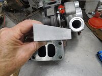
Well what ya know I happen to have some 3/16" plate in the shop and I'll just build a frame that supports the length of the shelf and then strong back the top so it can't bow.
IMG_6621.JPG

Sounded good and was good all the way until it came time to build it. I just don't get out in the shop all that often anymore. I get the new frame cut and ready to melt but what's the first thing that happens, batteries die for my helmet (there goes an hour closing up shop and off to the store). Then I didn't get but one corner done when this catastrophe happened - the dreaded empty spool
IMG_6619.JPG

Not having another couple hours to lose getting a spool (this thing has got to be installed in the morning) I dig thru the ole misc welding drawer and whatta ya know I find myself a small roll of .023. Gee, how old is this stuff, gotta be at least 20 years old and the packing is kinda of in tact, lets run it!

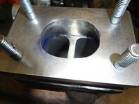
I don't even want to discuss the **** show that followed. I have no idea what was up but I tried everything to get a decent bead. No matter what I did to get decent penetration, she was a spitter. And none of us like a spitter right? :rolleyes:

IMG_6620.JPG
IMG_6623.JPG

Long story short its done and installed and when I finish up that room over the next couple days it will all make sense.
6.jpg
IMG_6664.JPG
IMG_6665.JPG
 
Last edited:
To avoid these ads, REGISTER NOW!

LXCam

ALLIANCE MEMBER
Joined
Apr 23, 2013
Messages
19,081
Location
AZ
I'm adding a couple detail shots.

Not fully convinced 7ga plate wouldn't bow (given enough time and gravity) even though its only 13" clear between the uprights I decided to strong back the width. The back was easy since it could live there forever. I just plug welded it in 3 places like the picture above. The front, well not so much. It needed to be removable if the day ever came the cabinet needed to be removed. That one required I come up with something that made sense and the structural engineer would sign off on.

So I made some inserts for 3/8" bolts for the front legs. Then counter sunk some 3/8" hardware that will face up and go through the front support. That one isn't on these pictures but will be when its all said and done.
IMG_6610.JPG
IMG_6611.JPG
IMG_6612.JPG
IMG_6640.jpeg
BTW, I completely forgot to do the through-bolts and countersinks before the table was all welded up and painted. So that night after a 14hr day I remembered just as I was about to go to bed...ain't that the best?!

So here it is 4:30am and I'm in the shop with only one cup of coffee in me, a cordless drill and a very dull countersink bit attempting to do something that supposed to look halfway thought out and professional and on site ready to install by 6am. Thank god for satin black paint is all I have to say. (y)
 
Last edited:

LXCam

ALLIANCE MEMBER
Joined
Apr 23, 2013
Messages
19,081
Location
AZ
Since today turned out to be get all the BS pictures off my phone day and since I can rarely share anything I do, these I can share :p123

Here's some BS camera pole stuff I had to come up with a solution for. The first ones were pole extensions and all the plans said where, "center line of lense to be 12'6" elv" and nothing else. So without replacing the existing pedestals I needed something that looked legit and could be easily retrofitted to the existing units.

I drew this up and submitted it to the EOR for approval. 2 months later we still hadn't gotten anything back and the GC took it upon himself to approve the design and off we went. Literally the day we got done installing these I received the returned submittal. Low and behold they approved the design but required inspection by the structural engineer before I had them powder coated............"well good FN luck on that one guys, you can come to the job and figure it out for yourself".

Here was my minor situation. Since these needed to slide and mechanically fasten to the existing pedestals which were powder coated, my sleeve had to allow for that additional MIL thickness so I didn't destroy the finish and also not be loose on the slip fit and tweek the receiver.

When I was welding up the sleeve, I had some lite gauge galv laying around and used that for my gauge. It seemed like a good idea and I even coated them with some lubricant to ease the pain of removing them. Sounded good in theory, but I had beat the holly hell out of them to remove.

The pics explain everything else from here.
IMG_5041.jpg
IMG_5044.jpg
IMG_5046.jpg
IMG_5445.jpg
IMG_5442.jpg
IMG_5441.jpg

For anyone that notices the back side access hole for the sealtight fitting, the pole was tapped for 6/32 screws for a weatherproof single gang cover. Also the sleeve mounting bolts were drilled through both pieces, then tapped for a 3/8 X 24 bolt (all four sides) so there plenty of meat for them to grab.
 
Last edited:

LXCam

ALLIANCE MEMBER
Joined
Apr 23, 2013
Messages
19,081
Location
AZ
The next one just happened to happen at the same time but the projects where 140 miles apart. This one was a problem of my own doing. Back when I bid this facility retrofit I never went on the roof and looked at what I was in for. It appeared to be your typical parapet style wall system with TPO roofing. No sweat, I'll get parapet mounts for all the perimeter cameras.

Man you should have seen the look on my face when I finally got up there to confirm how things would mount with the guys. Everywhere except the entrance we didn't have an issue with the exception that the CMU walls weren't solid grouted........who the F does that, it's a gawt damn jail you morons!.

My issue was the front, now envision this. The top of the parapet was 2ft wide, then vertically dropped down 9" to a 45 degree cant strip that just so happened to be 4ft in length. And the camera needed to extend out past the light fixtures. After some investigation of the original construction drawings I found out the Cant was framed with tin metal studs with 1/2" plywood cover. So I needed to really think this one thru.

What I ended up doing was using a 2ft X 4ft X 7ga baseplate that ended up being 3/8" toggle bolted to four of the studs, top/bottom and I had the County roofing dude do all the bed sealing and capping once it was installed.

Here was the next issue, accessing this camera without a boom lift was impossible, so I decided I'd build in a hinge point so the could be serviced from the roof. You might notice a support for the arm off the top of the parapet, I did that not just for support, but to keep it was swaying back and forth from the wind. BTW, all though I was there for laying this out and with the roofer the day we bedded the base plate, I ain't been back up there since to snap any pictures of the finished product at roof level.

IMG_5184.jpg
IMG_5185.jpg
IMG_5189.jpg
IMG_5192.jpg

IMG_5194.jpg
yav6.jpg
yav3.png

A little fun fact for all you potential no-good-doers. That camera is a 5 imager. 4 of them capture every square inch of the main parking lot and the bottom PTZ captures faces and license plates from the entrance/exit point 600ft away with incredible clarity. When I put this job together a couple years back the director wanted that ability and all though in theory I could pull that off, it was a little iffy. Boy was it cuul when it actually worked.
 
Last edited:

Jswain

Well-known member
Joined
Apr 26, 2013
Messages
2,450
Location
Calgary, AB
The next one just happened to happen at the same time but the projects where 140 miles apart. This one was a problem of my own doing. Back when I bid this facility retrofit I never went on the roof and looked at what I was in for. It appeared to be your typical parapet style wall system with TPO roofing. No sweat, I'll get parapet mounts for all the perimeter cameras.

Man you should have seen the look on my face when I finally got up there to confirm how things would mount with the guys. Everywhere except the entrance we didn't have an issue with the exception that the CMU walls weren't solid grouted........who the F does that, it's a gawt damn jail you morons!.

My issue was the front, now envision this. The top of the parapet was 2ft wide, then vertically dropped down 9" to a 45 degree cant strip that just so happened to be 4ft in length. And the camera needed to extend out past the light fixtures. After some investigation of the original construction drawings I found out the Cant was framed with tin metal studs with 1/2" plywood cover. So I needed to really think this one thru.

What I ended up doing was using a 2ft X 4ft X 7ga baseplate that ended up being 3/8" toggle bolted to four of the studs, top/bottom and I had the County roofing dude do all the bed sealing and capping once it was installed.

Here was the next issue, accessing this camera without a boom lift was impossible, so I decided I'd build in a hinge point so the could be serviced from the roof. You might notice a support for the arm off the top of the parapet, I did that not just for support, but to keep it was swaying back and forth from the wind. BTW, all though I was there for laying this out and with the roofer the day we bedded the base plate, I ain't been back up there since to snap any pictures of the finished product at roof level.

IMG_5184.jpg
IMG_5185.jpg
IMG_5189.jpg
IMG_5192.jpg

IMG_5194.jpg
yav6.jpg
yav3.png

A little fun fact for all you potential no-good-doers. That camera is a 5 imager. 4 of them capture every square inch of the main parking lot and the bottom PTZ captures faces and license plates from the entrance/exit point 600ft away with incredible clarity. When I put this job together a couple years back the director wanted that ability and all though in theory I could pull that off, it was a little iffy. Boy was it cuul when it actually worked.
Man, that looks like a mount strong enough for a jail! Nice job!!!
 

LXCam

ALLIANCE MEMBER
Joined
Apr 23, 2013
Messages
19,081
Location
AZ
Man, that looks like a mount strong enough for a jail! Nice job!!!
Thnx js.
It can do double-duty as a gibbet!
Hummm, maybe I should remake the end cap and add a pulley. 🤔


Wish I could share some of the extra cool stuff I’ve done over the last 5yrs. Unfortunately it’s either a potential security risk or proprietary design. And all though I designed and built it, damn **** belongs to the company.
 

Beerhippie

Well-known member
Joined
Oct 13, 2023
Messages
9,641
Location
Far NE Oregon
Thnx js.

Hummm, maybe I should remake the end cap and add a pulley. 🤔


Wish I could share some of the extra cool stuff I’ve done over the last 5yrs. Unfortunately it’s either a potential security risk or proprietary design. And all though I designed and built it, damn **** belongs to the company.
That's the downside of "work for hire".
 

IMCA38

Well-known member
Joined
Sep 21, 2007
Messages
998
Location
Bennet, NE
Did you do something to turn the exhaust away from the tank?
I’m just going to monitor for now. I don’t anticipate it will get that hot on the tank as there is some space. The plastic air cleaner case is pretty close and that’s not a problem. If I do find it’s getting hot, I can shift the sprayer to the right a little, and/or attach a heat shield to the tank.

UPDATE- I wired up the power from the battery to the sprayer and worked with the spray pattern. The muffler is about 6” from the tank and it is a little warm, but not melting hot. The bigger issue is that the Kitty Cat is leaving black marks on the white tank. I’m going to cut and bend a piece of sheet metal to shield the tank and catch the soot.
 
Last edited:

colindoyle

Well-known member
Joined
Apr 5, 2024
Messages
95
Location
Minnesota
IMG_0499.jpegIMG_0468.jpeg
IMG_0486.jpeg


On Saturday morning, I finished welding out the swim platform frame for that boat. Got a few ugly beads in there, I **** at welding out of position and this assembly had plenty of tricky spots to access. Now I think I might make a DIY passivation machine with a parts washing brush and a battery charger, erase all the sweet rainbow tints and better protect the metal from corrosion.

Flew the aeroplane about five hours over the weekend, too. The gear didn't collapse and the golf cart tires didn't explode, despite my best efforts.
 

WoodsTruck

Well-known member
Joined
Jan 12, 2013
Messages
1,019
You are a little more excited to climb in and fly a plane that is lightly considered to be held together with a bungee cord.
 
To avoid these ads, REGISTER NOW!

Nortonscustom

Well-known member
Joined
Jun 5, 2008
Messages
375
That's the least of it - my wings are fabric and spruce. I was cruising along at 2500' MSL and passed by a few soaring hawks and a flock of little white birds beneath me, then started thinking about the implications of a bird strike in cruise. :scared:
Well Colindolye after your post a while back I went down the Fisher Celebrity rabbit hole. I have a ways to go but when I retire my short list to build was either a Baby Ace, Pixie or a Hatz. The Celebrity has now been added to the list. Have a lot of questions for the Fisher folks at Air Venture this year.

BTW, don't hit a turkey vulture with your wing strut while flying doors off......trust me....
 
Last edited:

colindoyle

Well-known member
Joined
Apr 5, 2024
Messages
95
Location
Minnesota
Fisher has about 10 different plans-built biplane models, I'm not entirely sure what the difference is, but I think the Celebrity is more on the 'real airplane' end of the spectrum, in that it's a little heavier, a little bigger, and typically has a Lycoming or Continental in the nose, rather than a 2-stroke.

Flies about like a 100hp Cub. I imagine a Baby Ace or a Pietenpol is similar.
 

jcarapet

Well-known member
Joined
May 22, 2017
Messages
276
Location
Texas
Current project and logistical challenge. Building steel planters around the pool deck. These two pieces when combined will make a 4' wide X 34' long planter. The issues that will come out of that are setting it in place, and keeping the pieces straight in line.

The next one will be even longer and more complicated, so not even going tackle that yet.
 

Attachments

  • PXL_20240505_230740995.jpg
    PXL_20240505_230740995.jpg
    1 MB · Views: 119

Bodj Built

Well-known member
Joined
Feb 3, 2016
Messages
1,165
Location
Moorpark, CA
Current project and logistical challenge. Building steel planters around the pool deck. These two pieces when combined will make a 4' wide X 34' long planter. The issues that will come out of that are setting it in place, and keeping the pieces straight in line.

The next one will be even longer and more complicated, so not even going tackle that yet.

That'll be a challenge for sure. Is it corten? That stuff isn't cheap!
 

teleskier

New member
Joined
May 11, 2024
Messages
1
Standard mild steel, but 1/4" thick. This is what the high end landscape company was going to use, so don't feel too worried about it rusting through.
New to the forum. Doing a bunch of planters myself with 1/4" mild. In fact I am redoing all the edging in my yard to 1/4". Over shorter runs or where its not a big step it should have negligible bowing. Painted it on the inside to slow the rust, but not worried. For my place, I prefer it painted black anyway.

To keep my 32' x 12" wall straight I welded on the 1" angle like you and then added 1" x 3/16" stakes every 4 feet that protrude 4" into the ground Its not going anywhere; the lateral force it would take for a plant to move against the angle and ground stakes is likely not happening. It weighs probably 500#. I have a powerlifting son who deadlifts 600# to help with the transport.
 

jcarapet

Well-known member
Joined
May 22, 2017
Messages
276
Location
Texas
New to the forum. Doing a bunch of planters myself with 1/4" mild. In fact I am redoing all the edging in my yard to 1/4". Over shorter runs or where its not a big step it should have negligible bowing. Painted it on the inside to slow the rust, but not worried. For my place, I prefer it painted black anyway.

To keep my 32' x 12" wall straight I welded on the 1" angle like you and then added 1" x 3/16" stakes every 4 feet that protrude 4" into the ground Its not going anywhere; the lateral force it would take for a plant to move against the angle and ground stakes is likely not happening. It weighs probably 500#. I have a powerlifting son who deadlifts 600# to help with the transport.
We have a similar thought process. Here is an example from a 3'x3'x14'. I drilled a bunch of post holes down, filled with concrete, and put a couple sticks of rebar in each hole (have plenty from my driveway/shop slab). Those will eventually get welded to the side of the planter. I also for good measure bolted it against the side of the concrete. For the free standing planters I will just drill my holes/rebar on both sides and use more rebar welding them together to prevent bowing.

I am still undecided on painting the inside, but it has been eating at me to do so.

PXL_20240406_232917499.jpg
 

PugetDude

ALLIANCE MEMBER
Joined
Mar 13, 2013
Messages
22,271
Location
Superstition Mountains, AZ
We have a similar thought process. Here is an example from a 3'x3'x14'. I drilled a bunch of post holes down, filled with concrete, and put a couple sticks of rebar in each hole (have plenty from my driveway/shop slab). Those will eventually get welded to the side of the planter. I also for good measure bolted it against the side of the concrete. For the free standing planters I will just drill my holes/rebar on both sides and use more rebar welding them together to prevent bowing.

I am still undecided on painting the inside, but it has been eating at me to do so.

PXL_20240406_232917499.jpg
Planter looks great!
Column anchor bolts, not so much....
 

jcarapet

Well-known member
Joined
May 22, 2017
Messages
276
Location
Texas
Planter looks great!
Column anchor bolts, not so much....
LOL, took me a second to realize what you were saying as it's been so long. Medium length story. Ordered building from Mueller assuming porch was flat. Told the concrete guys to do a 1/8" slope on porch because it's part of pool deck. Totally forgot to tell Mueller to adjust porch columns...

Need to weld the columns to the bolts and wrap them eventually. Thats 8-9 major projects away though.
 

rockinacummins

Well-known member
Joined
Oct 27, 2013
Messages
1,706
Location
Wapanucka, OK
Yesterday’s project was a DOT bumper with a receiver hitch for my 2006 GMC C5500. It didn’t have a hitch when I got it, the previous owner removed the bolt-on receiver hitch. I didn't mind cuz I wanted a heavier hitch that functioned as a bumper anyway.

Started with some 2x5x1/4 tubing:

IMG_6616.jpeg

Burn some rods - 6010 root and hot, 7018 cap:

IMG_6617.jpeg

A little test fit:

IMG_6618.jpeg

Square it all up and glue it together. Add some corner gussets, end caps, and the receiver tube:

IMG_6629.jpeg
IMG_6630.jpeg
IMG_6631.jpeg
IMG_6632.jpeg

All that’s left to do is a recessed license plate bracket (because I’m confident it will get torn off where it’s at now), some safety chain attachment points, and a rattle can paint job. Everything was ground to a sharp bevel and 100% welded. I kept the receiver tube tucked in as far as I could to reduce the leverage from the trailer tongue and keep the overall length as short as possible. For the height of the hitch I used the average height of the hitches on the 3 pickups in my driveway.
 

scout4bta

Well-known member
Joined
Nov 2, 2017
Messages
90
Location
Willcox Arizona
I needed an adapter to go from a T30 flange on the 4BT exhaust manifold to a T25 flange to mount a HE221W turbocharger in place of the HX30W.
Bought a block of Ductile Cast Iron to make the weld on adapter and a small spool of Royal 44-30 wire.
 

Attachments

  • 01 DSCN2394.JPG
    01 DSCN2394.JPG
    372.2 KB · Views: 55
  • 02 DSCN2398.JPG
    02 DSCN2398.JPG
    227 KB · Views: 50
  • 03 DSCN2410_1.JPG
    03 DSCN2410_1.JPG
    342.8 KB · Views: 49
  • 04 DSCN2415_1.JPG
    04 DSCN2415_1.JPG
    244.8 KB · Views: 52
  • 05 DSCN2417_1.JPG
    05 DSCN2417_1.JPG
    260.3 KB · Views: 66

scout4bta

Well-known member
Joined
Nov 2, 2017
Messages
90
Location
Willcox Arizona
According to the Royal specs for welding thick cast iron you should use a "U" bevel @ 60° . This is my first experience with welding cast iron.
I used a make shift solar oven to preheat. The temp maxed out at 250F in 30 minutes.
And added a bung for the EGT probe.
 

Attachments

  • 06 DSCN2418_1.JPG
    06 DSCN2418_1.JPG
    228.5 KB · Views: 67
  • 07 DSCN2419_1.JPG
    07 DSCN2419_1.JPG
    248.4 KB · Views: 63
  • 08 DSCN2431_1.JPG
    08 DSCN2431_1.JPG
    280.6 KB · Views: 60
  • 09 DSCN2448.JPG
    09 DSCN2448.JPG
    248.4 KB · Views: 65

PugetDude

ALLIANCE MEMBER
Joined
Mar 13, 2013
Messages
22,271
Location
Superstition Mountains, AZ
Another batch of rabbit/rat/ rattlesnake screens for stucco wall drains. These are for my neighbor who is building a new home, deathly afraid of rattlesnakes.

I told her it was impossible to keep them out completely (she has 4 gates) but she wanted the block drain vents screened.

3/8 rebar frames, expanded metal. 3/8 conduit clips and Tapcons to anchor them to the block wall. Made this batch as a housewarming present. I really need to start charging for these. Between here and the mountain place I am sure I have fabricated well over 100 of them...

IMG_20240520_153916303.jpg
 
Last edited:
To avoid these ads, REGISTER NOW!
Top Bottom