Cheney Anvil & Vise Co. - Detroit, MI
pplication events
1879-11-18
Application granted
1879-11-18
Publication of US221781A
1896-11-18
Anticipated expiration
Status
Expired - Lifetime
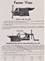
DescriptionJ. W. CHENEY. Cbmbined Anvil and Vise.
Patented Nov. 18, 1879.
WITNESSS-. J. W. CHENEY.
Combined Anvil and Vise.No. 221,781. Patented Nv.18,1879.
UNITED STATES PATENT OFFICE,
JAMES W. CHENEY, OF DETROIT, MICHIGAN, ASSIGNOR TO ARMILLA A. CHENEY, OF SAME PLACE.
IMPROVEMENT lN COMBINED ANVIL AND VISE.
Specification forming part of Letters Patent No. 221,781, dated November 1B, 1879; application tiled September 1l, 1879.
To all 'whom it 'may concern
Be it known that I, JAMES W. CHENEY, of Detroit, county of Wayne, State of Michigan, have invented a new and useful Improvement in Combined Anvil and Vise; and I declare the following to be such a full, clear, and exact description thereof' as will enable others skilled in the art to which my invention pertains to make and use it, reference being had to the accompanying drawings, which make a part ot' this specification.
My invention consists in a combined anvil and vise embodying the novel construction and arrangement of parts hereinafter described, and pointed out in the claims.
In the drawings, Figure l is a perspective view of a combined anvil and vise embodying my invention. Fig. 2 is a longitudinal central section of same by a vertical plane. Fig. 3 is a cross-section by a vertical plane on the line a; x ot Fig. 2 5 Fig. 4, a similar section on line y `i/v of Fig. 2. Fig. 5 is a plan view. Fig. 6 is a plan view of the under side of the anvil with the bed-plate removed, and Fig. 7 isv a plan view of the upper surface of the bed-plate when detached from the anvil.
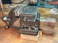
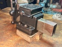
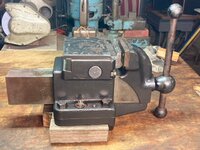
A is the anvil, B, a hollow space in its interior. C, is the adjustable or sliding jaw. It has a stem, C', which enters the hollow space B. The stem is provided with tongues C2 upon its upper and side faces, which lit into corresponding grooves in the body of the anvil, and a groove, C3 in its lower surface fits over a tongue, C4, on the projection A. These tongues and grooves serve to prevent all lateral displacements or tendency of the jaw C to rotate about its stem as it is caused to advance or recede by the action of the screw.
D is the screw. It passes longitudinally through the stern C/and a collar, d, serves to secure it near the handle to the jaw C in the nature of a swivel attachment, so that as the screw is run in or out it will carry the jaw with it. The screw D is tapped through a nut, E, which is prevented from moving by an arm, E', which projects into a corresponding recess in the bottom portion of the anvil, so that as the screw D is turned through the nut the jaw C is caused to advance or recede from the other jaw.
The interior space B is provided with a ridge or guide, b, against which the upper portion of the stem C or its upper tongue, C2, has a bearing throughout as it moves backward and forward. This is a matter of considerable importance in the construction of the device, because, if the stem C had a bearing only near the rear end -or heel of the anvil, it is apparent that after a little wear the jaw would be liable to tilt outward and fail to come to a snug bearing upon the interposed object, whereas the ridge or bearing b,bein g always-in contact with the stem at its inner end, affords a steady support against any such tendency. This ridge also aii'ords stiffness and strength to the upper part or face of the anvil. The screw, being entirely housed within the stem C', is kept free from dirt and grit, and is therefore always in good working order, and will wear a long time.
I provide an oil-hole, c, in such a location that when the jaw is expanded sufficiently far to expose the oil-hole the latter will be outside the nut, so that as the screw is run in it will thoroughly oil the thread of the nut. More over, the oil-hole in all ordinary use will be housed within the anvil, and cannot become stopped up with grit or dirt.
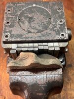
The anvil is secured to a bed-plate F, by a suitable pivotal bolt, F', which extends upward through the center of the bed plate and screws into the bearing-plate F2, which latter is constructed with straight sides that fit in grooves F3, formed in the inner sides of the anvil, and thereby prevent any rotary movement of said bearing-plate. The bed-plate is formed with a circular recess, within which is received the circular boss f2, formed on the lower end of bearing-plate F2, thereby allowing the anvil to be freely revolved on the bed plate when it is desired to adjust the anvil, and the bed-plate is, in turn, fastened to any support-as, for instance, a block or bench. Suitable bolts or screws f are provided for that purpose. This construction admits of the anvil being turned so as to present its point or vise in any desired direction for the more convenient access of the workman, and pins passed th ron gh the holes f and corresponding holes in the bed-plate will serve to fasten the anvil in any position.
G is a removable pivoted jaw. It is recessed into the face of the anvil, so as to be turned in any direction, as shown by the dotted lines in Fig. 5, thus enabling it to come to a square bearing upon the face of any interposed object,no matter whether its opposite faces be parallel or inclined to each other. Pins g, setting into corresponding holes iu the face of the anvil, serve to hold the jaw parallel to the adjustable jaw, except when it is desired to adjust it to an angle. This feature of recessing the pivoted jaw into the face of the anvil is important, inasmuch as it enables the manufacturer to readily dress off the face of the anvil, whereas, if the jaw were cast solid with the face of the anvil, or were attached to a projection extending upward from the anvil, it would be exceedingly difficult to dress and finish the face of the anvil, owing to this projection. An anvil of this character is exceedingly simple and strong, and makes a convenient tool for the workshop and farm.
The form of attachment to the block may be varied without departing from my invention. For instance, it may be fastened rigidly without having the revolving feature at all, or any suitable revolving attachment may be employed. So, also, instead of making the tongues U2 upon the stem C', the stem itself may be made square or angular and accomplish the same purpose of accurately guiding the jaw.
The orifice into which the pivoted ,jaw is set opens through into the interior space B, and any foreign matter will drop through, and not collect in the orifice to close it up and impair the fit and operation of the jaw.
The removable jaw may be replaced by any other suitable form of jaw-as, for instance, one suitable for holding a section of pipe, &c.
What I claim is- 1. In a combined anvil and vise, the combination, with the face of the anvil, of a pivoted jaw adapted to be rotated horizontally about its pivot, substantially as set forth.
2. In a combined anvil and vise, the combination, with the face of the anvil, of a readily removable pivoted jaw adapted to be rotated horizontally about its pivot, substantially as set forth.
3. In a combined anvil and vise, the combination, with the face of the anvil, of a pivoted jaw, the base of which rests upon said anvil face and is adapted to be rotated in a horizontal plane thereupon, and means for locking said pivoted jaw rigidly to the anvil, substantially as set forth.
4. A combined anvil and vise consisting of an anvil having the stationary jaw of a vise pivoted to its face and capable of horizontal rotation about its pivot, and of a movable jaw provided with a stem fitting within a recess in the anvil, and a screw for operating said movable jaw, substantially as set forth.
5. In a combined anvil and vise, a removable jaw combined with the face of the anvil, said removable jaw set into a recess which opens into the interior of the anvil, whereby dirt is prevented from collecting in the said recess, substantially as set forth.
6. In a combined anvil and vise, the combination, with the anvil provided with perforated supports or lugs and a bearing-plate secured against rotation within grooves in the anvil, ot a bed-plate provided with a circular depression for receiving a circular boss Ourthe bearing-plate, said parts connected by a pivotal bolt, the bed-plate being provided with any desired number of holes in its outer edge, and readily-removable pins for securing the anvil to the bed-plate at any desired angle of adjustment, substantially as set forth.
7. In a combined anvil and vise, a pivoted jaw combined with the face of the anvil, and pins setting into holes in the face of the anvil, or their equivalent, whereby the jaw may be set square for ordinary use, substantially as described.
Witness my hand at Detroit, Michigan, this 30th day of August, 1879.
JAMES W. CHENEY.
Witnesses:
CHARLES M. WOODRUFF, WILL M. PORTER.
|