I blame you guys for my recent purchase!
")
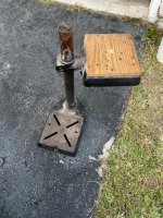
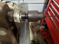
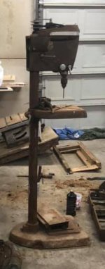
Wednesday, I picked up a running 100 series for $100 that seems to be in pretty good shape. I have been doing a bit of research on here, but I believe this is what I have:
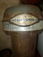
Base tag is 103.23130 = Craftsman 100 from 1948-1955
Slotted head screw = pre 1951
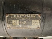
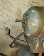
Motor model 115 6960, date D1 48 = 1948
3rd set of pulleys for speed reduction.
Unique things so far:
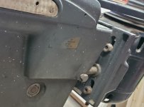
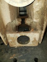
Extra toggle switch on base (front n center)
Extra hole(s) about 1" from slotted screw on both sides
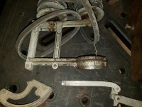
Missing so far:
Depth gage/feed stop parts
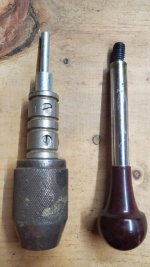
Thumb screw to retain chrome handle (return spring)
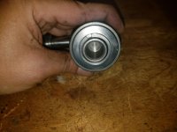
Collar on chuck
Set screws for other handles?
For now, I just plan to get it cleaned up and fix/replace what needs done and maybe later on I can tear it down and do a thorough rebuild.
To do:
Oil spindle = done and its less sticky
Oil shafts = done to aid future disassembly
Oil motor
Install grounded cord
Thanks for the entertainment!
Ryan