To avoid these ads, REGISTER NOW!

Overseas Jack Rebuild Help Tutorial.

Keep

Well-known member
Joined
Jan 1, 2009
Messages
1,398
Location
Oshawa, Ontario
Just a bump to say Thank You to Hiball.

A guy in my car club was going to toss one of these today, I promptly saved him the hassle of scraping it. I remembered this post from a few years ago and used it to tear this jack apart.

I found the problem in short order, seems some cast flash or **** from the threads broke off and embedded itself in the plastic cup holding the big o-ring. He said it would work with lite weight but would not hold heavier items.

So for the cost of some shop time and a new o-ring and cup I will have another 3 ton floor jack, unless the guy wants it back once its fixed.

Thanks again for all the info/help you provide on here. If shipping to me wasn't such a ***** you would be my choice for the repair parts needed.

B
 
To avoid these ads, REGISTER NOW!

skulldrinker

Well-known member
Joined
Dec 25, 2011
Messages
1,171
Location
Bolingbrook, IL
My 1976 era Rockford 2 Ton Floor Jack was squealing like a pig trying to pull and push it across the floor. When I would jack up the car the car would shift instead of the jack rolling with the rising angle change. The wheels were sticking. I finally broke down and removed the front wheels and greased them. I then flipped it over and used a brush to push some grease into the rear swivel wheels ball bearings. Now the jack dances across the floor with one hand and quiet as a mouse.
 

Jeeper

Well-known member
Joined
Dec 25, 2006
Messages
2,124
Location
Round Rock, TX
My 1976 era Rockford 2 Ton Floor Jack was squealing like a pig trying to pull and push it across the floor. When I would jack up the car the car would shift instead of the jack rolling with the rising angle change. The wheels were sticking. I finally broke down and removed the front wheels and greased them. I then flipped it over and used a brush to push some grease into the rear swivel wheels ball bearings. Now the jack dances across the floor with one hand and quiet as a mouse.

What kind of grease did you use? Anything special?
 

kenzo42

Member
Joined
Oct 3, 2012
Messages
7
3me3F63Ia5L35Ne5M4cbpf1145cd3d93a1979.jpg

3Ge3F33N35V65H45Mfcbp0f438051b75e1612.jpg


Are rarity! But is it worth purchasing for $50?
 

BB767

Well-known member
Joined
Dec 24, 2009
Messages
3,724
Location
Philo, IL
3me3F63Ia5L35Ne5M4cbpf1145cd3d93a1979.jpg

3Ge3F33N35V65H45Mfcbp0f438051b75e1612.jpg


Are rarity! But is it worth purchasing for $50?

You bet it is! I bought mine new in 1976...

IMG_7679.jpg


...and it's worked flawlessly for the last 36 years.

IMG_7680.jpg


These were made in Japan under contract for Sears...

IMG_7682.jpg


...Green is Good! From the look of the saddle in your picture it's hardly had any use. It is most definitely worth $50. I bet it'll last you the rest of your life, it's worth servicing if needed unlike those cheap Chinese made jacks that are flooding the market. These Green Japanese Sears jacks are high quality.

IMG_5547.jpg


After restoring a 1942 Walker floor jack I know quality when I feel it! :D

Thomas from the Restored 1930's Auto Shop

http://www.garagejournal.com/forum/showthread.php?t=51567
 

dieselZR2

New member
Joined
Dec 9, 2012
Messages
2
Thanks for the new U-cup for my 3.5T Craftsman (ShinnFu) jack Hiball, I received it Friday and got it put in. With some email help from "Edgar", another member here.

Question: In your original post you mention replacing the o-ring style piston seal with a Ucup seal. In addition to the above Craftsman jack I have a very recent OTC 1504A 3T jack (which I wish I'd never bought). What are the chances of finding a ucup to replace the piston seal in it someday. In your experience is the Cylinder ID and Rod OD (of O-ring style piston sealed jacks) typically such that a Ucup can be used? As it is so new I hate to tear it apart just to take measurements. Thanks both to you and Edgar for all the help! You guys put a lot of perfectly good iron back into operation here!
 
Last edited:
OP
H

Hiball

Well-known member
Joined
Apr 30, 2009
Messages
14,026
Location
Missery
Thanks for the new U-cup for my 3.5T Craftsman (ShinnFu) jack Hiball, I received it Friday and got it put in. With some email help from "Edgar", another member here.

Question: In your original post you mention replacing the o-ring style piston seal with a Ucup seal. In addition to the above Craftsman jack I have a very recent OTC 1504A 3T jack (which I wish I'd never bought). What are the chances of finding a ucup to replace the piston seal it it someday. In your experience is the Cylinder ID and Rod OD (of O-ring style piston sealed jacks) typically such that a Ucup can be used? As it is so new I hate to tear it apart just to take measurements. Thanks both to you and Edgar for all the help! You guys put a lot of perfectly good iron back into operation here!

Yes.. In most cases you can replace the Shell/oring style pistons seals with Ucups. There are on occasion some modifications that have to be made to the ram itself, as some of those shell seals carry a ridge that has to be addresses by removing it or modifying washer/shell to make a seamless transition.
 

dieselZR2

New member
Joined
Dec 9, 2012
Messages
2
Yes.. In most cases you can replace the Shell/oring style pistons seals with Ucups. There are on occasion some modifications that have to be made to the ram itself, as some of those shell seals carry a ridge that has to be addresses by removing it or modifying washer/shell to make a seamless transition.

That's good news. If I need to get a little machining done that's no big deal. The existing cylinder ID and space for seal height are the important things I guess, since they can't be changed.
 

vision976

Member
Joined
Dec 27, 2012
Messages
5
Location
Buckley, WA
Hiball,

I have an AllTrade 3 Ton "Load Buster" Floor Jack Model # 891-J-3-MJ which I won in as a prize in a trap shoot in 1995.

It has never worked properly, meaning that it would always slowly leak down no matter how much I tightened the valve controlled by the jack handle. In fact, I have rounded out the flats on the valve stem where the star gear engages and spun the gear on the shaft in my efforts to make it stop leaking down.

Thanks to your excellent tutorial, I think I figured out what was wrong, years after the fact. The jack had begun to leak down faster and now it doesn't raise at all. After contacting Alltrades in CA and being told it's an obsolete jack with no parts available, I went searching the internet and stumbled upon your excellent tutorial.

I removed all of the valve(s) pieces today, leaving the bottle jack in the frame. Attached is a picture of what I found. There was no steel ball under the over-pressure valve spring train, only the T-shaped ball seat as shown in your pictures. That's probably why the darned thing always leaked down.

I did use a pencil magnet to fish any balls out from their wells and the ones mentioned were the only ones I could find.

There was only one large ball under the allen-headed bolt. Not certain if it should have two. May the guy who assembled it couldn't count or got interrupted when the hydraulic unit was put together.

So I have 4 questions for you: 1) what size steel ball do I need under the over-pressure spring system? 2) should I have a smaller steel ball under the big ball under the allen-head bolt? 3) I don't understand how the valve controlled by the star gear actually functions. It's got the steel ball in the bottom of the orificed and threaded well in the casting, the ball is pressed down upon by the square-shanked shaft above; but the shaft itself (at least on mine) does not have any threads on it other than where the star gear is attached by the nut. And the housing it fits into does not have threads, so I don't understand how rotating the shaft could apply pressure to the steel ball to seal the passage. What's up with that? How does this valve work to stop fluid flow? 4) Do you have any spare bleed valve shafts and star-wheels that might fit my jack? I've pretty well rounded off the flats and chewed up the teeth over the years of attempting to stop the leak-down.

Thanks in advance for your response.

John
 

Attachments

  • jack_valves.jpg
    jack_valves.jpg
    142.8 KB · Views: 167

EDGAR

Well-known member
Joined
Aug 21, 2010
Messages
437
My advice is to turn the jack upside down and strike, with a hammer, the botton of the pump body right under the valve holes and see if any ball falls from the holes. Sometimes the balls get stuck to their seats. If there is oil in the holes above the bottom ball, the pencil magnet may not pick it up. I know this because I have used a pencil magnet to do this and more often than not it does not pick the ball because of the oil. Try to use a pencil type flashlight to look inside the holes to see if the balls are there, but to do this you need to remove the oil from the holes anyway.

The usual size for the over pressure steel ball in chinese jacks is 1/8" but you should look in the hole and verify that the hole where the oil moves through (not the hole where the ball fits in) is smaller than the 1/8" ball. Other jacks, like the USA made Walker/ Lincoln/ Hein Werner, which use the same type of pump among them, use a 5/32" steel ball.

You indeed need two balls under the allen headed bolt otherwise the pump will not work at all. The smaller ball at the bottom allows oil to come up from the oil tank when you pump the handle up, as pumping up draws oil from the tank. When you pump the handle down, the oil movement pushes this ball against it seat redirecting the oil to the back of the ram. Without this ball, the oil goes back to the tank and no lift is produced. The upper (bigger) ball allows the redirected oil go behind the ram, but when you stop pumping, the oil trying to come back from the ram closes the big ball against its seat. These are one way valves.

Many problems with leaks down are due to this big ball no sealing perfectly against its seat. If you leave the handle down after raising a load and it starts to raise by itself (but not because the handle return spring moves it) at the same time the car slowly comes down, that means the big ball is not sealing correctly. Understand that this ball is holding the weight of the car and it is held in its place just by the oil pressure on it. There should be zero leakage here.

The size of the smaller one-way-valve ball is usually 1/4" (6mm) but this size can vary with the different jack manufacturers. Another size could be 5/16".

A common mistake with leak downs is that people over tighten the release but this almost never solves the problem. The release ball usually seals OK because it is pushed strongly by the square shaft agains its seat so there is little chance of leakage here. The problem usually lies with the other balls, assuming the ram seal is not broken or worn out.

You mention that the square shaft has no threads. Does that means that you can pull it off from the round body and insert it back without turning it? In the photo it is shown inside the round body but it can come out of it ( by turning it). Maybe you can show it outside of its mount so we can see that it has no threads? Any way, there should be threads on the opposite end of the square shaft. The way this works is that the round washer with the square hole, which, by the way, does not move as it is pinched by the big nut assembly, holds the square shaft in place (does not turns) and because of the threaded end it is supposed to have, the square shaft goes up or down when you turn the release gear with the handle. It is important to know that the thread direction here is reversed.

Also, this is a tricky assembly to mount back on the pump as you should not let the square shaft bottom up as you bolt the big nut into the pump body. You have to turn the gear a little, as if openning the release, so the square shaft does not bottoms. This way, the square shaft moves away (up) from the steel ball. If it bottoms, the release gear itself is going to get stuck and you will not be able to turn it easily by hand or with the handle, requiring that you unbolt the assembly enough so that you are able to turn the release gear a little more until the whole release assembly is bolted down to its original position.

Edgar
 
OP
H

Hiball

Well-known member
Joined
Apr 30, 2009
Messages
14,026
Location
Missery
Hiball,


So I have 4 questions for you: 1) what size steel ball do I need under the over-pressure spring system? 2) should I have a smaller steel ball under the big ball under the allen-head bolt? 3) I don't understand how the valve controlled by the star gear actually functions. It's got the steel ball in the bottom of the orificed and threaded well in the casting, the ball is pressed down upon by the square-shanked shaft above; but the shaft itself (at least on mine) does not have any threads on it other than where the star gear is attached by the nut. And the housing it fits into does not have threads, so I don't understand how rotating the shaft could apply pressure to the steel ball to seal the passage. What's up with that? How does this valve work to stop fluid flow? 4) Do you have any spare bleed valve shafts and star-wheels that might fit my jack? I've pretty well rounded off the flats and chewed up the teeth over the years of attempting to stop the leak-down.

Thanks in advance for your response.

John

1. As stated normally its 1/8" but you first need to verify that the original ball isn't still in the valve. It would have never worked without it..

2. Yes.. Here again, double check the valve. It's probably still down there. It takes a very small diameter magnet to fit down inside the galley.

3. If I recall that style threads internally, which means the square drive is connected to the gear threads.

4. Yes, I have some New/used gears, there are a few different styles that very from tooth count to mounting style ( round and oblong), spare balls are no problem, but I suspect yours are just hiding from you.

No worries... It's hard for people to understand how the release mechanism works, the key is the silver washer (square ID) when this piece is stationary, it allows it to rise/fall when the gear is turned. I've addressed it numerous times in this thread, most recently around post 18?. Below is a copy and paste, that seems to be helpful.


The Valve has to be completely seated against that washer Solid or the Release wont work.

1. Insert the Ball
2. Inert the Washer
3. Insert the Oring
4. Lengthen the square by Unscrewing it from the Release Assembly.
5. Insert the Square section into the Washer
6. HOLD the Gear and thread the Assembly into the Hydraulic Block
7. When it bottoms out (Square against Ball/Seat)
8. Rotate the gear to the Right which will pull the inner square back up into the Assembly, Meanwhile screwing the assembly down into the block.
9. When the Assembly is completely seated, This will seat the washer and whenever you turn the Gear it will Rise and Fall. Thus seating and unseating the ball for Proper Jack Operation.
 
Last edited:

vision976

Member
Joined
Dec 27, 2012
Messages
5
Location
Buckley, WA
At Edgar's suggestion, I flipped the jack over and tapped the jack body with a hammer which caused two additional balls to fall out. The 1/8th inch from the over-pressure valve mechanism and a 1/4 inch from the pump well, it fits under the largest ball in the same well.
 
OP
H

Hiball

Well-known member
Joined
Apr 30, 2009
Messages
14,026
Location
Missery
At Edgar's suggestion, I flipped the jack over and tapped the jack body with a hammer which caused two additional balls to fall out. The 1/8th inch from the over-pressure valve mechanism and a 1/4 inch from the pump well, it fits under the largest ball in the same well.

What once was lost, is now found... Very good. :thumbup:
 

vision976

Member
Joined
Dec 27, 2012
Messages
5
Location
Buckley, WA
Ok, With Edgar's and HiBall's help, I figured out how the release valve mechanism works on my jack. I was buffaloed as to how the valve could possibly work at all, because there there no threads visible to me that could be used to impart a force to seat the ball bearing against the orifice.

After going back out to take a picture of the bleed valve housing to show it had no internal threads and that there weren't any visible threads on the round shaft with the square tip, (except those that secure the star gear to the shaft), I got to looking at the square tip and thought it might be a separate part from the round shaft that had the o-ring, since it appeared to have a different color steel. My eyes don't see up close very well, and that was one of the problems. None-the-less, it took a very tightened set of vise grips on the rounded off flats of the round shaft and the application of quite some amount of torque to the square tip with a crescent wrench to break it loose. That baby was jammed in there.

Now I could understand how the valve works. They say a pictures worth a thousand words and it would have helped to see the square tipped bolt unscrewed from the outer round valve body to enable me to figure out the pressure was applied to the ball.

So when the handle of the jack shaft is rotated clockwise, the driven gear on the valve shaft rotates counter-clockwise. Thus torque is applied to the round shaft and because the washer with the square hole in it prevents the square tipped bolt from rotating, the square tipped bolt is "unscrewed" from the round shaft body and pressure is applied to the ball to prevent leakage.

OK, the way the valve mechanism works wasn't evident to me. :lol_hitti

A couple of pictures are attached.

But now I'm still buffaloed as to why the jack never worked correctly from day one and always leaked-down. Perhaps the release valve was mis-adjusted at factory and the square-tipped bolt could never apply sufficient pressure to seat the ball, except that doesn't make sense since counter-clockwise rotation of the valve body would unscrew the square-tipped bolt and apply the pressure. (unless it were jammed in round housing but I think that unlikely).

More likely there were little pieces of steel debris from machining operations that were keeping one of the balls from seating. The jack did work, it would rise but it would always slowly leak down despite my Neanderthal efforts to torque the release valve shut.

When I was using the magnetic probe to attempt to retrieve all of the balls, I did pull some metal debris from the over-pressure well.

Anyway, now maybe it's time to take it all the way apart and check the main seal on the ram. The seals in the pump housing appear to be fine.

John
 

Attachments

  • all_valve_parts.jpg
    all_valve_parts.jpg
    65.6 KB · Views: 123
  • square_tipped.jpg
    square_tipped.jpg
    48 KB · Views: 845
  • Shaft.JPG
    Shaft.JPG
    60.8 KB · Views: 112
  • release_valve_body.jpg
    release_valve_body.jpg
    67 KB · Views: 109
  • Four_balls.JPG
    Four_balls.JPG
    78.2 KB · Views: 124

vision976

Member
Joined
Dec 27, 2012
Messages
5
Location
Buckley, WA
So I put everything back together paying very close attention to the assembly and seating of the release valve mechanism per Edgar's and Hiball's instructions. And the jack now functions, at least on the bench, it raises and lowers. I can't tell if it leaks down yet.

Hiball:

There are 12 gear teeth; measured diametrically across the tips; about 1.68 inch, if measured across 4 teeth in the jaws of a vernier caliper, it's about 1.645 inch.

Since the release valve shaft flats which index the star gear are so buggered up and the gear rotates when it shouldn't, I'd just as soon purchase an entire release valve housing, round valve shaft (with square headed inner bolt) along with the gear, washer and nut as a unit from you if possible.

At the very least, I'd like to buy the round valve shaft that the flats are ruined on, plus a new gear.

The shaft outside diameter is about 0.627 inch. The valve housing measures 0.940 across the flats of the head, and 0.930 across the outside of the threaded body.

Can we make a deal? Feel free to PM me.

Thanks to both of you for the help.

John
 

elav

Well-known member
Joined
Nov 12, 2008
Messages
122
Hiball, thank you for this thread and the parts I got from you (twice). Second time I rebuilt the jack before losing the parts you sent! Another jack saved, thanks!
 

vision976

Member
Joined
Dec 27, 2012
Messages
5
Location
Buckley, WA
Yesterday, I JB welded the gear to the valve shaft to eliminate the clearance of the rounded off valve shaft flats to driven gear; bolted it up carefully to center the gear on the shaft.

Added jack fluid to compensate for what I'd lost when I inverted the jack to tap the little balls out of their respective wells, that I couldn't retrieve with a pencil magnet alone.

After the epoxy cured, and cycling the jack up and down a few times to bleed it, I jacked the left rear axle of my F350 off the ground. I left it up overnight and the jack did not leak down, so the original leak down problem which had existed from Day 1 in 1995, must have been associated with the little metal shavings I pulled out of the over-pressure valve well with a magnet or perhaps they came out of another well when I inverted the jack get the last two of the four balls out of their wells.

All is good now.

Thanks for the insight and recommendations, Hiball and Edgar.

John
 
To avoid these ads, REGISTER NOW!

rodsatheart

Member
Joined
Oct 2, 2012
Messages
17
OK. Someone want a jack. Put in new seals and cup and does exactly the same thing. Might raise a couple of inches, but will not hold any pressure. Like it's low on oil. You want it, come get it. I need a working jack today, so will have to go buy another.
 

GeorgiaHybrid

Well-known member
Joined
Sep 9, 2008
Messages
3,763
Location
Extreme NW Georgia
OK. Someone want a jack. Put in new seals and cup and does exactly the same thing. Might raise a couple of inches, but will not hold any pressure. Like it's low on oil. You want it, come get it. I need a working jack today, so will have to go buy another.

Let us know where you are located and I'm sure someone on here will take you up on the offer.
 
OP
H

Hiball

Well-known member
Joined
Apr 30, 2009
Messages
14,026
Location
Missery
OK. Someone want a jack. Put in new seals and cup and does exactly the same thing. Might raise a couple of inches, but will not hold any pressure. Like it's low on oil. You want it, come get it. I need a working jack today, so will have to go buy another.

Sounds like its a Valve Issue, Possibility of Missing Parts? Wrong Order? Release Valve?
 

EDGAR

Well-known member
Joined
Aug 21, 2010
Messages
437
Rodsatheart

Your problem could be the main overload bypass. By your description, with a leaking overload you could raise the lift arm a little but as soon as it feels a load it will stop lifting. When it stops lifting depends on the amount of leakage. A overload leaking all the time will raise the arm very little if any. An overload that is not tightened enough will lift up to the point where the heavy duty spring yields to the oil pressure. Therefore, the tighter the overload bypass, the more weight it lifts. Since your jack has a quick lift feature, it has two overload bypasses, one for the "power" lift and another for the quick lift.

Check how many turns it takes to close, or bottom, the main overload screw, which is under a threaded cap. You should have about one turn to one turn and a half before it closes completely. The red arrow , on the attached thumbnail, indicates the main overload bypass. The blue arrow indicates the Quick lift feature overload bypass. This is a parts breakdown for an OMEGA 25030 made by Shinn Fu. This jacks uses the same pump as your MVP jack. MVP is now part of Shinn Fu but the name is not used anymore, now they use the name PRO LIFT. This pump is also used by the ATD 7331 floor jack, ATDTOOLS.COM.

By the way, the quick lift overload bypass is not tightened as much as the main overload. It is tightened up to the point where the quick lift features starts to work. Any more tightening will blow an o-ring, and its back up ring, of the quick lift system as this system is not supposed to lift any weight. So, when the quick lift overload bypass is set correctly, it starts bypassing the moment the saddle makes contact with the chassis.

By the way, your jack uses a 24mm x 40mm u-cup. If you used a 25 x 40 it is not going to work, the difference is enough to cause a leak between the ram and the u-cup's inside diameter.

http://www.shinnfuamerica.com/ProductDetails/Omega_Lift_Equipment/Magic_Lift_Service_Jacks/25030/360

On the link above, click where it says OWNER'S MANUAL to see the complete parts breakdown for the Omega.
 

Attachments

  • OMEGA 25030  1.JPG
    OMEGA 25030 1.JPG
    66 KB · Views: 213
Last edited:

rodsatheart

Member
Joined
Oct 2, 2012
Messages
17
Update. pulled it back apart yesterday to re-clean and check for mistakes. Found 1 ball in wrong place. While disassembling it this very little check ball falls into my hand from the front somewhere. I'm talking about .030 diam. Looking over the patent diagram trying to find a home. NOT. Finally locate the only logical location for it under the manual valve in the lower part of the body. Only port it will seal. Clean and blow out all passages and put it back together, bench bleed it and it worked !!!!
Wait there's more.
Put the jack back together and try a partial stroke and it worked and held pressure, so I attempt another one, it goes up about 1 inch and drops like it lost prime.
Get home today and try it. Rapid travels to full extension (big smile), but no holding power (bigger frown). Check overload and is set at 1 1/2 off seat.
Retry and wont barley lift 2 inches. It's like this thing wont prime.
I have to be missing something guys. Please help.
 
OP
H

Hiball

Well-known member
Joined
Apr 30, 2009
Messages
14,026
Location
Missery
Update. pulled it back apart yesterday to re-clean and check for mistakes. Found 1 ball in wrong place. While disassembling it this very little check ball falls into my hand from the front somewhere. I'm talking about .030 diam. Looking over the patent diagram trying to find a home. NOT. Finally locate the only logical location for it under the manual valve in the lower part of the body. Only port it will seal. Clean and blow out all passages and put it back together, bench bleed it and it worked !!!!
Wait there's more.
Put the jack back together and try a partial stroke and it worked and held pressure, so I attempt another one, it goes up about 1 inch and drops like it lost prime.
Get home today and try it. Rapid travels to full extension (big smile), but no holding power (bigger frown). Check overload and is set at 1 1/2 off seat.
Retry and wont barley lift 2 inches. It's like this thing wont prime.
I have to be missing something guys. Please help.


Rest assured its something simple... Its Incredibly hard to diagnose over the internet. Where did you put the Small Ball that you found? "Manual Valve? Are you doing these tests Light or under Load? It almost sounds like you have a Ball in the Wrong Port and its affecting Oil Intake/Exit.

Maybe... Some pictures showing the Valve contents/order in correspondence to where you took them out.
 
Last edited:

rodsatheart

Member
Joined
Oct 2, 2012
Messages
17
All tests have been done light as it will not lift even myself. Was actually talking about the release valve. (brain not functioning).
The small pipe (I'll call a supply tube) which is probably for rapid travel and fits into the bore in the main body. Pull it out and there is a passage in the 6 o'clock position directly under the release valve. That is where I put it. The only location that appears to have a seat small enough.
I have located all balls according to their original location and checked them to two separate schematics, one of which is the actual patent drawing.
http://www.google.com/patents/US5755099?printsec=drawing#v=onepage&q&f=false

The only other thing I can think of is that some debris dislodged from somewhere and is lodged in a check ball seat, poss. A3.
 
OP
H

Hiball

Well-known member
Joined
Apr 30, 2009
Messages
14,026
Location
Missery
All tests have been done light as it will not lift even myself. Was actually talking about the release valve. (brain not functioning).
The small pipe (I'll call a supply tube) which is probably for rapid travel and fits into the bore in the main body. Pull it out and there is a passage in the 6 o'clock position directly under the release valve. That is where I put it. The only location that appears to have a seat small enough.
I have located all balls according to their original location and checked them to two separate schematics, one of which is the actual patent drawing.
http://www.google.com/patents/US5755099?printsec=drawing#v=onepage&q&f=false

The only other thing I can think of is that some debris dislodged from somewhere and is lodged in a check ball seat, poss. A3.

Yeah.. Remove that ball, I don't recall any balls below that quick lift tube/washer. It sounds like the Speed/power changeover valve might be part of the problem, its one of those valves that has to be adjusted under load. The Process I use to adjust the "single" transfer valves is to back the adjusting plug out, and using some trial and error I put the jack under a load. What your looking for is a the lift arm to raise against the load (quick) and then when it needs to lift the car it transfers over to the "power" side. This transfer is accomplished by this adjusting plug/spring/cone/seat. I simply tighten the plug down till I get a crisp transfer. Of course if your working valve or release components aren't correct this adjustment is useless.
 

rodsatheart

Member
Joined
Oct 2, 2012
Messages
17
That baffled me also, as the drawing only shows and lists 4 and with the .030 ball I have 5. I'll look at things more tomorrow or Wed. when I get it torn down and cleaned again. If all checks out ok, what else could be causing the bleeding issue that i might look for while I'm in there ?
 

EDGAR

Well-known member
Joined
Aug 21, 2010
Messages
437
RODSATHEART

Your jack's pump actually has six balls in total. In the patent they mention 4 balls, namely A1, A2, A3, A4 but not shown is the top ball of the one way valves; below this one would be ball A1. There is supposedly another one behind a plug.

Ball A1 should be 5.5mm in size while the top ball not shown should be 7.5mm or about 5/16". These are the two balls of the one way valves for the main piston. Below see the thumbnail I presented before and see the locations of the balls (red circles). I have my doubts about the ball circled in blue as this could be a passage drilled to connect the other oil passages and then the hole is plugged after but you may check this since you are taking it apart.

A2 seems to be the one way valve for the speedy lift feature. Allows oil to go into the speedy lift system tube but it can not come back trough here to the oil tank or the pump piston.

A4 ball seems to let the oil behind the main ram, and the speedy lift system, go back to the oil tank when you open the release valve. Also prevents oil going to the speedy lift system from going behind the main ram when the release valve is closed and you are pumping the handle.

A3 ball is a one way valve, the way it is shown in the patent, oil can only go behind the main ram, but not come out. I am not sure about how this one works or when, as the flow diagram is not clear in this respect and it is mentioned in the patent explanation briefly.

A1 is the one way ball that allows oil, drawn by suction from the oil tank, to come under the pump piston when you raise the handle but can not go back the same way, so it goes behind the ram when you pump down the handle.

The top ball (# 34 on the ATD 7331 mentioned below and over A1 in the patent) of the one way valves allows oil to go behind the main ram from the pump piston when you pump the handle but closes as soon as you stop pumping. This is a very important ball as any leak here will allow the lifting arm come down slowly while at the same time the pump handle will rise if left in the down position. The oil goes back to the oil tank.

I have to study the patent a little more to understand the way the oil flows as it is shown in one dimension but the vertical oil passages are obviously not in the same plane.

I am also including a parts breakdown of an ATD 7331 (ATDTOOLS.COM) which uses the same pump. In this picture you can also see six balls. The numbers are:

33 = 5.5 mm two of these,
34 = 7.5mm,
55 = 6.35mm (1/4"), two of these
38 = 3mm

I do not know if this sizes correspond to yours, although they should.

You mentioned a ball sized .030, can you confirm this? This in fractions would be 1/32", quite small. Would the position of this ball be A4 as this is the smallest ball shown in the patent?

Also, when you reinstalled the cylinder, how much did you tighten it? Did you marked the cylinder so you could return that mark to were it was before? If you needed an extension tube on the pipe wrench to remove the cylinder, did you use the extension tube to tighten it back? I ask this because the cylinder goes on very tight and if there is any leak in the cylinder/pump body connection, it could give the impression that a valve is faulty. You may need to change the o-ring at the bottom of the cylinder to achieve a good seal with pump body. Alternatively, you could use liquid thread sealant, not teflon tape.

Also, could you confirm the u-cup size you used, as the link you presented, from GJ member BINOVC, had incorrect info on the size of the u-cup and he said he was going to correct this info. It should be 24mm x 40mm and not the 25 x 40 presented in that link.
 

Attachments

  • OMEGA 25030  BALLS.JPG
    OMEGA 25030 BALLS.JPG
    64.5 KB · Views: 134
  • ATD 7331  BALL LOCATION.JPG
    ATD 7331 BALL LOCATION.JPG
    66 KB · Views: 133
Last edited:

rodsatheart

Member
Joined
Oct 2, 2012
Messages
17
Technically I have 8 in mine, but 3 are just plugs. One in either side and one in the bottom.
It is very small. .030 is a estimate, but prob. not to far off. I will be able to measure when it is back apart.
Replacement cup is a 24x40.
I used the same tools and process to tighten as I did to remove. It is very tight.
All new o rings.
 

rodsatheart

Member
Joined
Oct 2, 2012
Messages
17
It lives !!!!!!!!!!!! Don,t know and really don't care what was wrong, prob. piece of debris snuck in some how because all I did was clean, clean, clean.
Now I need the correct procedure for setting the Speed/power changeover valve and the overload valve. I currently have the overload set at 1 1/2 turns off lightly seated.
Thanks for all the help folks. It's nice to have it back working again.
Hiball: The seal works great. Actually seals better that the orig. Little snug, but some use will take care of that.
 

EDGAR

Well-known member
Joined
Aug 21, 2010
Messages
437
RODSATHEART

Since you already have the main overload bypass set, you just need to back up the speedy lift overload bypass and then tighten it again little by little, like maybe 1/3 or 1/2 turn at a time and then test it by pumping the handle. At some point the lifting arm will rise fast, so when this happens you may give it a little more turn, but not more than 1/4 of a turn just to compensate for any down the road softening of the spring. But, do not tighten it any more than that. If it is tightened to much, you will blow the o-ring and its back up ring located at the base of the small diameter tube of the speedy system requiring the removal of the cylinder to replace. Of course, this is assuming the speedy lift was working correctly before taking the pump apart. In other words, you are adjusting it very light so it bypasses right away at contact.

The setting of the speedy lift feature overload bypass is done without any load on it, of course, as this system is not designed to lift any weight other than the arm itself.

The way this works is that the arm rises fast and the moment it makes contact with the car chassis, the speed overload bypass starts bypassing oil back to the oil tank and it keeps bypassing all the time you are lifting the vehicle. In other words, it never stops working, it just is not lifting fast as it is bypassing oil.

Be aware that it is not really a changeover from speed to power since the "power" system is also pumping oil at the same time the "speed" system is working, it is just that the speed system starts bypassing at contact with any load while the power system continues working as ususal. You can see this because your jack should lift a load in the "power" mode even if the speedy lift does not works, or is not adjusted, now that the jack is working right. In simple words, both work all the time but only one bypasses at contact.

The main overload bypass only bypasses when you exceed the weight it is adjusted to lift which is not necessarily the rated weight of the jack. The more the main overload bypass is tightened, the more weight it can lift.
 
Last edited:
OP
H

Hiball

Well-known member
Joined
Apr 30, 2009
Messages
14,026
Location
Missery
The way this works is that the arm rises fast and the moment it makes contact with the car chassis, the speed overload bypass starts bypassing oil back to the oil tank and it keeps bypassing all the time you are lifting the vehicle. In other words, it never stops working, it just is not lifting fast as it is bypassing oil.

Edgar ive been extremely busy at work and in the Shop as of Late, I would like to Discuss some of your "Points" on How the Speedy lift works. First off.. Lemme say, I dont rebuild many of these Jacks, Most customers dont wish to put the money into them. I have though owned and still own a few of the Michelin jacks that ive picked up over the Years. Everything ive Learned about them has been from First hand experience and Shop time, and im always interested in Learning how things Work.. . You claim that he "Speedy Lift Valve" or "Sequence Valve" per the Patent info for anyone following simply bypasses back into the Reservoir once that initial Pressure has been set. Ive read the Patent info, and that statement confuses me because if the Oil being displaced by the Pump Piston has a choice of either filling the Inner cylinder or simply taking the path of least resistance and dumping back into the Reservoir. How does the lift a Load?. Ive Read Section 4 which basically translates on how this system works and My Head is ringing from all the "Patent" lingo. With that said... It's been a long day on the rail.

My Reasoning of calling it a "Changeover" Valve is because "If" its too light, It seems the Main Cylinder doesnt fill completely with Oil when the Lift arm raises. Ive always attributed this to a "Light seat", which affects Vacuum and doesnt allow the cylinder to fill completely with the raising of the Lift arm (quick), thus requires More pumping to fill the voids, before it will lift a Load. Obviously... IF you Crank the Valve down completely you will blow out the Orings and Or rupture the Quick lift tube.. <--- I seen a picture of that Here.

Again... My Procedure for setting these jacks up is to first get the Speedy lift set up, I start with a Overload setting of 1-1 1/2 turns out. Put it under my Test station which has a cylinder about 12" off the ground, I back the Quick Lift Adjustment off considerably and Pump (Valves full) till i can get the Arm to reach the Cylinder in 1 Down stroke/Hold. Once this happens i Reset, turn the speedy lift valve very little and Repeat till i start to see PSI building on my Gauge (Power) within a pump or two after initial contact. I have found that there is a fine line on these jacks that "Seems" to want to bypass versus build Gauge Pressure. It doesnt take much of a Adjustment to make a world of difference between getting a Nice Lift versus a soft one.

Its very common for People when they start having Hydraulic Jack problems to try and fix there problem by Adjusting things and such. As you probably know and id bet you'll agree, its Generally a Seal issue. I normally end up with Jack that is either way out of adjustment, Missing components and story goes... "This Jack was working Perfectly and loaned to a Neighbor, Brother or Cousin and Now it doesnt work" So ive had alot of practice with these jacks but its always been Trial and Error with Me.

Thoughts?
 
Last edited:

EDGAR

Well-known member
Joined
Aug 21, 2010
Messages
437
For HIBALL and for anyone following this.

First let me start by saying that in general, bypasses always bypass to the tank, whether thay are the ram bypasses or any type of speedy lifty bypasses.

Second, these are two separate systems. The main ram will lift as it should even if the speedy system is not working and the speedy lift will lift as it should ( when set correctly) even when the ram isn't working. Understand that when the bypasses are set correctly both systems are working at the same time, all the time, but one bypasses at some point but oil keeps flowing through it. In other words, they are involved but not compromised. All this assuming that you have good seals. Of course, if one of these system bypass is completely open, meaning that it is bypassing a lot of oil, poor performance can be expected from the other system, as too much oil can be redirected to the open system. So we are dealing here with bypass systems sealing correctly.

Third I do not like to call the speedy bypass an "overload", as it is usually refered to, because that gives the (mistaken) impression that you need some overload (heavy weight) to happen before it starts to work. The only overload it needs is to feel just a little weight before it starts bypassing. More to this below.

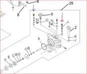
To fill the space behind the ram with oil when the speedy system is working but the jack has not reached the chassis yet, there is a passage, per the patent, that connects the oil tank to the cylinder and this passage has a check ball or a one-way ball identified as A3. When the handle is pumped, part of the oil goes to the speedy lift and part of it goes to the ram, there is no choice here. Of course, the amount of oil pumped behind the ram is not enough to fill the space behind the ram so here enters into action that check ball A3. The suction created by the ram moving forward draws oil from the oil tank to supply the oil necessary to fill all the space behind the ram. When you stop pumping, the A3 check valve closes and the ram retains the oil behind it.

This works the same way as those false "quick lift" systems that connect the lift arm pivot or shaft to a pedal and when you step on the pedal the arm is raised mechanically and if the release valve was closed beforehand, the arm would stay up. The ram is drawing oil from the oil tank even if you are not pumping oil with the handle.

The speedy system is set light because the "changeover" happens the moment the arm touches the car. The only purpose of the speedy lift is to raise the arm quickly and should start bypassing the moment it makes contact with the chassis. At that point the ram, which should have drawn enough oil from the tank to fill the space behind it, keeps lifting as any jack does. If you set this bypass to tight, you run the risk of blowing the o-ring and its back up, at the bottom of the speedy lift tube. This system is not designed to lift any weight apart from the weight of the lift arm itself.

That the lift seems soft is a common problem with jacks having quick lift features because some oil is going back to the oil tank. This means that the bypass valve is openning, and stays open, the whole lenght of the pump action, so at that moment, the jack is loosing some pressure from the pump piston. Because of this, it is unlikely that you are going to have a crisp lift each time you pump, the same way you would have with a non speedy lift jack in good condition. Also, jacks with speedy lift systems usually take a little longer to lift a load because of the oil bypassed to the tank. In other words you have to pump more times. I have heard complaints on how quick the arms lift up to the chassis but then it takes a lot of pumping to lift the car. And this happens with good seals.

Also, another problem with these pump having speedy lift systems is achieving a good air bleed ( or priming of the pump). Sometimes, the soft feel when lifting is increased because these type of pumps have more oil passages and more spaces inside the pump that can trap air. Because of this, these pumps may require a more thorough bleeding procedure than regular non speedy pumps.This may require lifting the jack from the front end a little, while pumping ( release valve open) to help that air move out. Sometimes this works right away other times it does not, so you may have to keep bleeding the pump a bit more.

Since the two systems are independent, adjusting the speedy lift one way or another will have no effect on how the main ram works or how soft or crisp the lift feels. Also, because of this independent functioning, you can set the speedy before or after setting the main ram overload. The way to set it then is to back up the bypass, tighten little by little and test, and them stop tightening the bypass threaded plug the moment the lift arm starts lifting fast. You don't need to set it under load/pressure, or any tighter, as the oil going to the speedy lift system to push the ram out fast, or the oil bypassing from it, will not go to the ram to help fill the space behind it or help to achieve a crisper and/or faster lift. Tightening it more thinking that it is going to provide a crisper lift may not work because this speedy bypass has to bypass at some point so you are going to lose some oil pressure and the pump action is going to feel not so crisp.

Since these are simple systems, you can not stop the speedy overload bypass from bypassing all the time after a load is felt by the jack. That would require a more elaborate system of valves to stop sending the oil it sends to the speedy lift and send all the oil flow to the ram.

If the speedy lift feature was strong enough, parts wise, and if there was no bypass of oil to the tank from the speedy bypass, you could have the speedy lift system help lift faster and probably crisper, but unfortunately, it does not work like that.

About the "ligth seat" issue where you think you lose vacuum, if the bypass is closed, and you have a good seal at the seat, even if it is set light, there should be no leakage of any type there, either of oil or of vacuum. If you are having a vacuum leak, or think that it is a vacuum leak, that does not allow to fill the space behind the ram, that problem has to be somewhere else, like for example the oil passage, and its check ball, that supplies extra oil to the ram when the quick lift is working and pushing the ram out fast. Or maybe, the u-cup is not sealing well enough when the ram is going in the forward direction to be able to draw all the oil needed behind the ram. Remember, as I mentioned before, that although the pump piston is sending oil to the ram, it is not sending all it needs when the speedy system is working, so the extra oil needed comes directly from the oil tank by suction by whatever method the pump designer/engineer provided for this. A u-cup not drawing enough oil could be one that even being new, may fit slightly lose in the cylinder and not achieve a good seal when moving forward because of this, even if it seals OK under load.

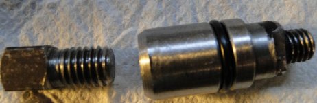
Also, the speedy system oil pushing out the ram stays inside the space in the ram where the speedy system tube fits because the small o-ring the ram has at its base seals this tube. This o-ring prevents this oil from going behind the ram to fill the space behind the ram. So oil from the speedy system is not used to fill the space behind the ram whether it bypasses or not or even if it leaks because these are two independent systems working together. Of course, if the o-ring is worn and leaking, then you are going to have oil leaking to the space behind the ram but the speedy lift will probably not work at all.

As for a tighter speedy lift bypass setting, a test would have to be performed to find how much weight the speedy system can lift alone, with the main ram overload backed up and bypassing only for this test, before the o-rings sealing it break up. Then the speedy lift could be set somewhat less tight so it bypasses before reaching the point the o-rings break up, specially the botton one at the base of the speedy tube which seems to go first than the top one. Perhaps this way a slightly nicer and faster lift could be achieved without damaging these o-rings. If the o-rings fail sometime latter due to the continued stress on them (fatigue), go back to the lighter setting as this system is really not designed to lift heavy weights, as I mentioned before.

The problem with the patent cutaway drawings is that these show only some of the oil passages but these do not show the bypasses and the oil passages going to them so it is incomplete and therefore confusing.

Mention of the A3 ball is made in the section titled "DETAILED DESCRIPTION OF THE PREFERRED EMBODIMENTS" secong page, second paragraph, I believe.
 
Last edited:
OP
H

Hiball

Well-known member
Joined
Apr 30, 2009
Messages
14,026
Location
Missery
Edgar... I'm still don't see how the "sequence valve" can continue to bypass into the reservoir "and" still work on the low side. I've studied the flow chart (fig 1) and ive read section 3 and 4 and 5 and see no path from the sequence valve (B) to the reservoir with exception of the relief valve (C) and or opening of the overload (D). It appears that when the valve opens the "opening pressure" is set correctly, it stays open and bypasses to the "overload valve" (D) which is connected to the "relief valve" (C) and then the A2 check valve (when the sequence valve is open/cylinder pressure exceeds quick lift tube pressure by the oil drawn in via check valve A3) which protects the quick lift tube from the higher PSI pressures associated with the lifting the load.

Thus... We both know that what conditions a "heavy" sequence valve seat will cause, too "light" and oil will flow into chamber (1) versus the quick lift chamber (14) till the cylinder PSI Exceeds the sequence spring. Which is why I associate that valve as a "Changeover". Simple in design? Absolutely....

And I'm not questioning your method for setting up these units, it sounds like have a plan of attack that works, and i havent noticed any issues on my end. I suspect the adjustment between working/not working is very minimal. I'm only interested in Understanding exactly how these jacks work, which is why I printed the patent info out and have studied it.

If I'm Mistaken, please reference the text section and ill read up some more... And yes those drawings are very crude, but the flow chart/text seems to make sense.
 
Last edited:

EDGAR

Well-known member
Joined
Aug 21, 2010
Messages
437
HIBALL

I know what the problem is. After studying the patent a little more I realized something. The design of the pump shown in the drawings is different from the design of the pump used in the MVP floor jack owned by GJ member RODSATHEART.

The design shown in the patent was a preliminary design presented there so as to be able to file for the patent. This design is not the final design slated for production. The design simply shows the different elements devised by the designer to make the pump work the way it is supposed to work. What was patented here was what the pump does, namely, lift the lift arm quickly. They call this feature the “ONE TOUCH”, meaning that the arm would rise to the load in only one pump.

The specific shape or design of the pump was not patented as such. Even the same patent description specifies that this is not a final design and that it is subject to design changes as long as the quick lift feature is maintained, which is the reason for this invention.

Even though the drawings shown with the patent and the actual design of the pump share the same patent number, they are different. The patent does not restrict revisions or modifications, all that is needed is that the pump does the function it was designed to do, which is to lift quickly the arm. I also checked the patent number for the new BLACKHAWK G 737, which uses the same pump as the MICHELIN G735, and the drawings in the patent show a different pump design from the pump actually used in these jacks.

The pump as shown in the patent's drawings has only one safety valve named “safety valve D” in the text. This safety valve or overload bypass only works with the main ram. There is no safety valve for the speedy lift system, because the way the pump was designed does not needs it. Now, there is the “sequence valve” whose function is to divert the flow of oil from the inner tube of the speedy system to the back of the ram when this inner tube, and the cavity it fills (41), is full of oil. When the arm makes contact with the load, no more oil can enter this inner tube so the oil pressure generated by the next pump of the handle will push open the sequence valve and redirect the flow of oil to the ram.

Since this pump shown in the patent does not have a dedicated bypass valve for the speedy system, no adjustment is possible, whether it is light or heavy.

With this preliminary design as shown in the patent, with no bypass for the speedy system, there is no bypassing of oil to the tank reservoir. So, Hiball, do not look for the passage of bypassed oil to the oil tank from the speedy inner tube, because there is not one in the pump as designed and shown in the patent.

At some point in time this design was revised/modified, so the final pump design slated for production, manages the flow of oil in a different manner.

The final design of the pump manufactured has a second bypass added to regulate the speedy lift feature.

There must be a reason why the design was changed. I am speculating that the sequence valve did not work as well as expected. One thing is the theoretical performance and another is the actual performance. So maybe they decided to change the way the oil flow inside the pump was managed by adding the second bypass.

I am also thinking that the sequence valve may have been eliminated from the final design when they added the second bypass but this need to be verified by opening one of these revised pumps and removing the cylinder, so as to be able to look for anything that resembles the sequence valve, with its spring and the conical seal. If there is nothing like this in the pump body, that means that the speedy system works now in a different way because now the oil could not be redirected to the ram by a sequence valve.

Now that I think about it, if the speed system o-rings are leaking in a pump built as shown in the patent drawings, these might leak enough oil to prevent the sequence valve from working/opening as the oil going to the speedy inner tube would keep leaking and not allow the piston pump to generate enough oil pressure, when the handle is pumped, to open the sequence valve. In this case, the oil would take the path of least resistance, which would be the leaky o-rings. Or maybe the sequence valve opens erratically providing poor lift performance. Maybe this is the reason the design was changed. The way the pump is designed now, the pump will still lift a load even if the speed system is leaking oil and not working, as it may not need to open a sequence valve for the ram to work.

The revised pump design, used in the MVP jack, with a second bypass valve dedicated to the speedy system now has a path for the bypassed oil to return to the oil reservoir.

The same basic design, used in the revised/modified MVP pump is used in the MICHELIN G735 3.5 ton jack, in the new BLACKHAWK G 737, and in the OMEGAS with the MAGIC LIFT feature. There are some changes as some pumps use an universal joint as a release instead of a release gear. All of these jack are made by Shinn Fu.

I have removed the cylinders from MICHELINs and I do not remember seeing anything like the sequence valve but, I was not looking for a sequence valve at that time so I would need to look again.

My recommendations for adjusting the speedy lift bypass apply only to the revised pump design and not to the pump as designed originally (as shown in the patent).

It would be interesting to find out if the pump in the patent was ever built as designed and then modified because of poor performance or if the design was changed before any pump was actually manufactured for sale.

Now, for the adjustment of the speedy bypass, the reason I recommend setting it light is to protect the o-ring , and its back up ring, located at the bottom of the inner tube from being blown out. Since there may be people who may think that “more is better“, they may want to tighten the bypass to much thinking that the jack is going to lift the car faster, like one of those aluminum jacks used in NASCAR races, which, of course, will not happen.

The speed bypass can be set a little tighter as long as it bypasses before any damage is done to the o-rings.

As for the speedy bypass bypassing all the time in the revised/ modern pump, it has to happen because the oil going to the speedy system has to go somewhere after the arm makes contact with the load. The speedy system will want to push the ram faster but the load on it will not let this happen, so the oil has to go somewhere, so it goes to the bypass. This is of course assuming that there is not any sequence valve in the revised pump design.

Hiball, you have a MICHELIN, if its speedy system is working OK, as an experiment for your own entertaiment, back up the speedy bypass enough and you will see that the quick speed feature stops working. Tighten it again and it works again. If you want to see the need for the speed bypass to bypass all the time after the lift arm makes contact with the load, tighten the speed bypass as much as the ram overload bypass so it does not bypasses when the arm makes contact with the load and see what happens ( do this test last!). Also, see that the jack will work lifting a load even if the speedy feature does not work because it is leaking oil due to worn out o-rings, for example, or if you backed up the speed bypass for the purpose of doing the test.

Another test that can be performed is to back up the main overload so the ram can not lift any weight. With a working speedy system, the arm will rise quickly up to the load, but will stop there and not lift any more because at that point, the bypass has started bypassing, or should have started to bypass. The handle can be pumped forever and the bypass will keep bypassing forever too, each time the handle is pushed down. The moment the pumping is stopped, the bypass closes, waiting to open again if the handle is pumped again. And if it is bypassing, the oil is going back to the oil tank. So the speedy bypass regulates how the speed system works and to do this it has to bypass all the time after contact with the load.

As I stated before, the speedy system is not designed to lift any weight other than the weight of the lift arm itself. So after it does its job of quickly lifting the arm it should stop working. And the way to stop working is to bypass the oil to back the oil tank. So there is no need to tighten the bypass too much to do its work.

Hiball, I remember you saying in one of your post that you new someone at Shinn Fu. Maybe you can have this person find out if the redesigned pumps use the sequence valve or if it was eliminated due to poor lift performance and if the second bypass was added to manage the oil flow in a different way from the way the sequence valve was supposed to do.

I was thinking of sending an e-mail to Shinn Fu to ask this, but I had a bad experience with one tech person there. I needed to find the part number for a part as the number was not shown in a parts breakdown. I had to speak with this tech person 5 times and each time he gave me a different, and wrong, part number. I think that these tech persons have little knowledge of the products they sell; maybe they are just sales persons answering technical questions.

If I am wrong in any of what I said here, I will admit it, as the purpose of this is to learn more about how these pumps work.

One of the thumbnails below shows where the patent mentions that this is not a final design and improvements or modifications can be made to it. The other thumbnail shows the pump design used in the MVP. This pump design is also used in the Omega 25030 with Magic Lift.
 

Attachments

  • one touch design changes.JPG
    one touch design changes.JPG
    29.4 KB · Views: 66
  • OMEGA 25030  1.JPG
    OMEGA 25030 1.JPG
    66 KB · Views: 86
OP
H

Hiball

Well-known member
Joined
Apr 30, 2009
Messages
14,026
Location
Missery
Edgar... There is definitely a difference in the 3 valve units, versus the Newer 4 valve units... Here Again, I'm not sure "exactly" how they operate. I do have some rough info (turns in/out) that I scavenged off a unit that I picked up at a auction. I really don't mess with these "single pump" Speedy lift/Magic Lift jacks much.. I keep the seals in stock for customers who want to fix there own stuff, but rarely do I rebuild them. As cheesy as the foot pedal quick lift jacks are, they actually work pretty good and have minimal working parts that IMO only add to the longevity of the Jack, Hense why I really enjoy Weaver jacks. I "Did" have a friend/aquaintnce at the KC shinn fu plant, but I tried to contact him in regards to some "Jack stand" chatter that was circulating here and after not receiving a response, I tried to call and he was no longer there. I really dislike dealing with Shinn fu, I have a account but my experience with there Tech guy is that he likes to talk more than listen to what I actually need. Unfortunately... Some stuff is only available thru them (without paying retail).
 
Last edited:

WhyMe

Well-known member
Joined
Jan 28, 2013
Messages
87
Do pumps like those in engine hoist work the same? i had a old China made one that would pump up, but as soon as a load was put on it, it would not pump further. I tried getting parts for it, but everyone i spoke to told me that parts are not available for these oddball Chinese made ones.
 
To avoid these ads, REGISTER NOW!
Top Bottom