To avoid these ads, REGISTER NOW!

Truss Design

bczygan

Well-known member
Joined
Nov 4, 2009
Messages
22,002
Location
DETROIT! Arsenal of Scrappers
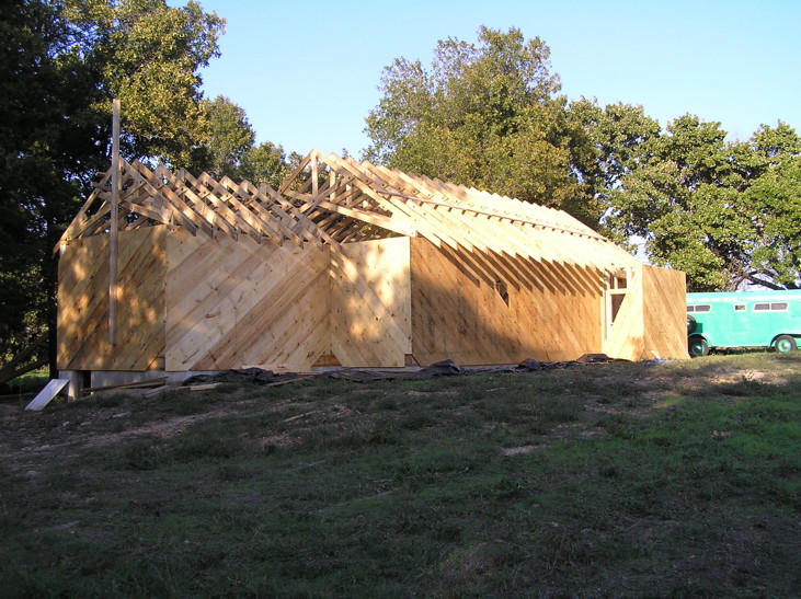
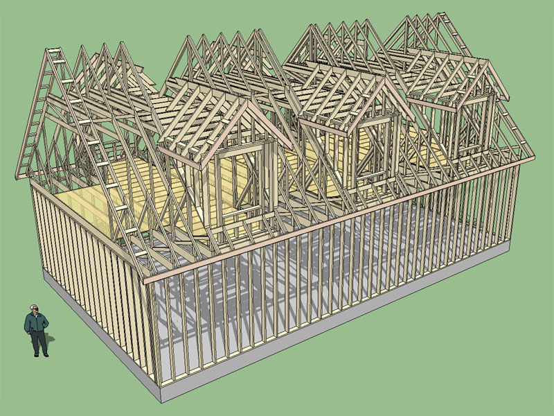
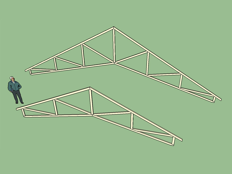
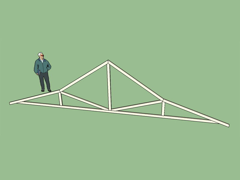
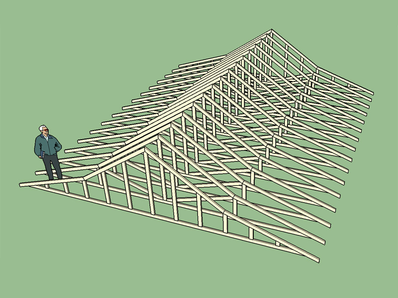
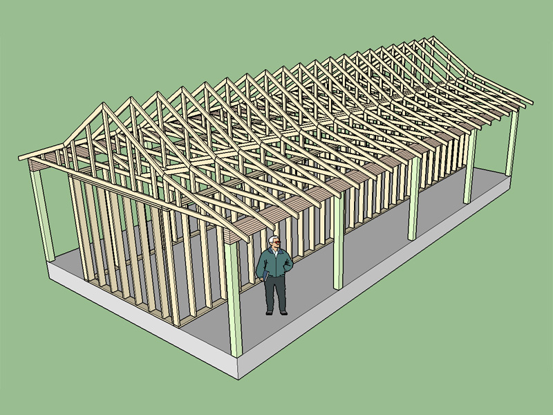
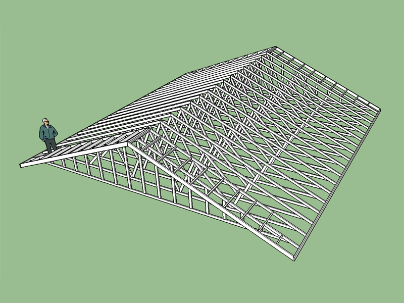
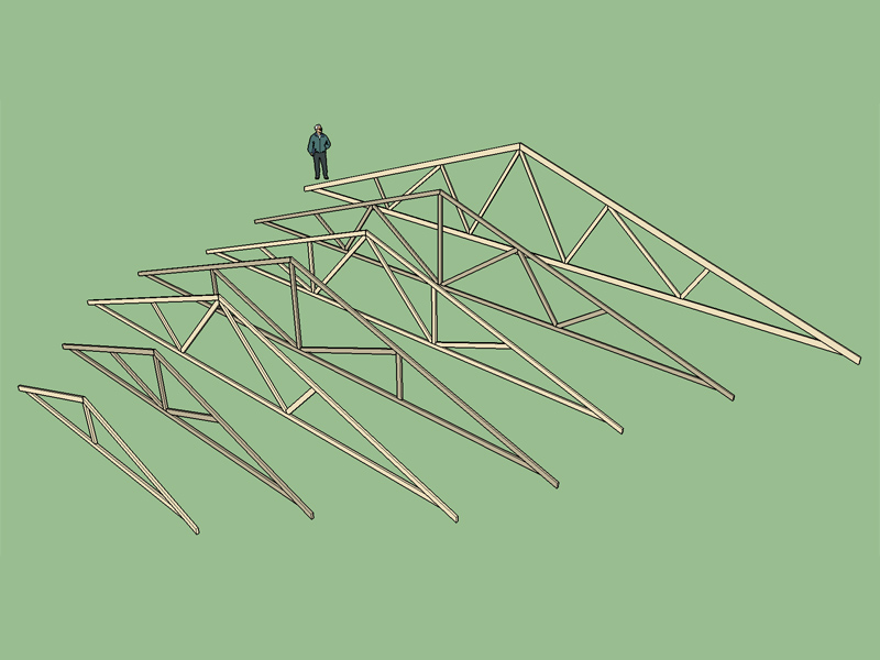
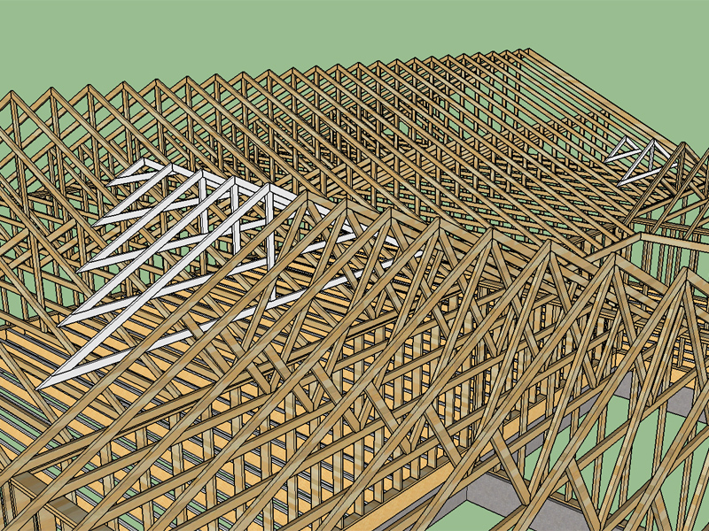
I work as a designer for a residential builder of homes ranging from 1,800 sq. ft. to 5,000+ sq. ft. Some of the roofs on the larger homes get quite complicated, but we figure them out before we send our plans out to the truss designers.

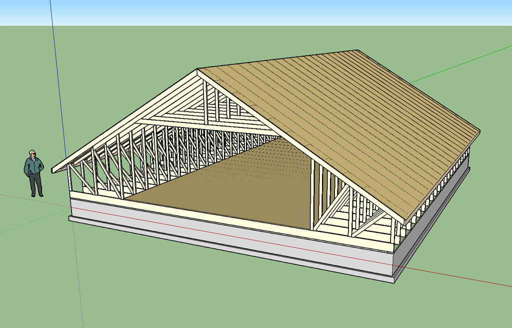
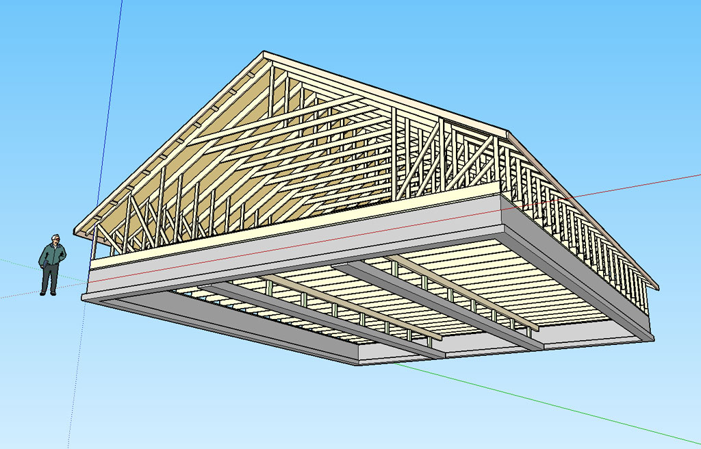
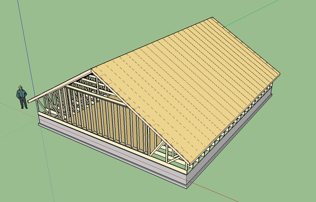
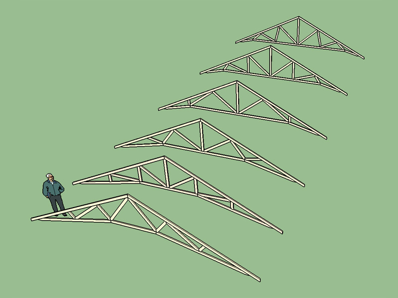
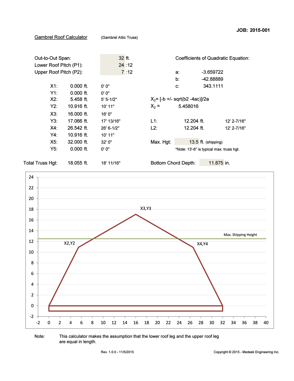
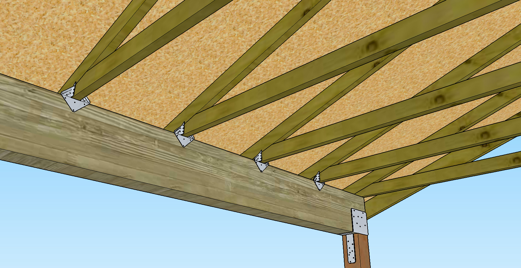
We specify pitch, overhang, and heel height. The drawings show whether or not a roof line is clipped back, at a different plate height, different truss heel, stepped up in the middle due to a ceiling treatment, etc. If attic trusses are used we specify the size of the bottom chord to handle the weight we anticipate the floor system/ bottom chord will need to support.

As long as the trusses are designed around these criteria we really don't care how they they are built, where they put the girder for the jacks on a hipped roof, etc. Once the trusses are designed we receive an overall layout and a drawing of each individual truss with all of its calculations to approve before they are built. We verify the pitch/overhang/heel/ceiling types and the span distance then trust that the calculations and webbing are correct. The liability for that part is on them.

Personally, I don't see how a tool like this is valuable to a designer like me. The truss design and structural load calculations within the truss are things that we ever need to worry about. We design for 45 lb. per linear foot of truss when calculating headers and structural beams. This is more than enough to cover our bases.

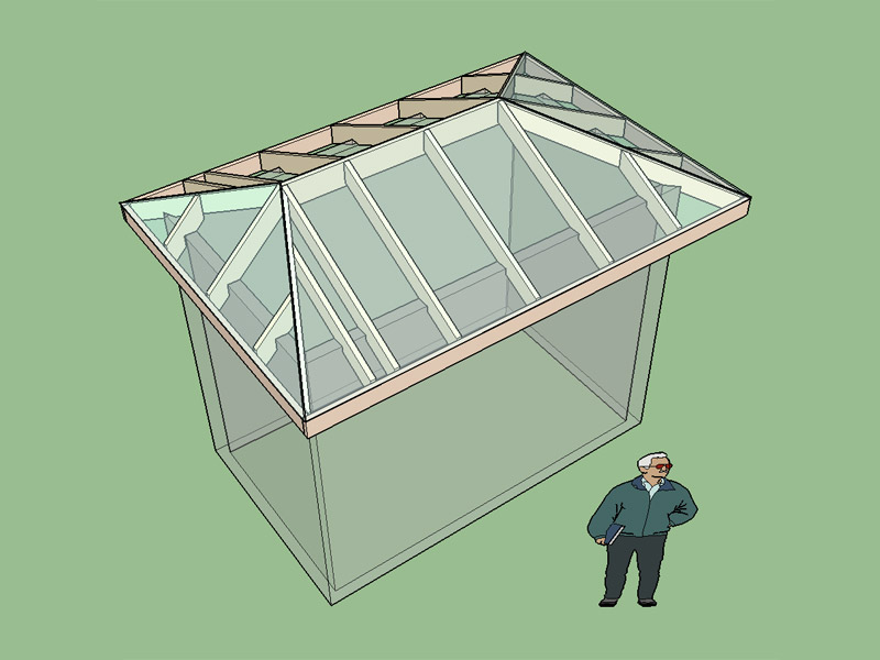
Personally, I am so tired of overly complex ceiling and roof designs. Too many chances for leaks and expensive re-roofing, which with our cheap disposable shingle culture, happens far too frequently anyway.

So many 5000SF McMansions with just two people in them. They will be a drug on the market when the baby boom passes.

Bill
 
To avoid these ads, REGISTER NOW!

JettaGetUpandGo

Well-known member
Joined
Jun 3, 2015
Messages
685
Location
Pewaukee, WI
Why bother with the ballpark when you're getting exact point loads and placements back from the truss manufacturer?


By the time we receive the truss drawings the foundations have already been poured, steel columns/beams in the basement are already in place, and rough framing has already begun. Trusses arrive at the job site in a matter of days after approval.

The 2x6 exterior walls are more than enough to support any truss load we will ever encounter. There are only a few questionable areas:
-Over wide window sets we will use a 2-ply or 3-ply LVL. Sometimes this is overkill for the truss loads, but it's cheap.
-Where there is an exterior wall on the second floor with truss loads that does not sit on top of a wall on the floor below we add flush LVLs in the floor system below and pick up those points with a column and steel beam in the basement. Again, it is cheap to over engineer this.
-Areas with a covered porch. These scenarios vary greatly, but we size beams based on the 45 lb. per linear foot number just like the above scenarios.

Some customers make changes that affect the footprint just days before the hole is dug. For us to have the trusses designed ahead of time to be able to calculate the actual loads would delay the start of the project if a change is made, affect the schedules of our subcontractors (approximately 50-60 homes in progress at any given point), and cost us more to have the trusses redesigned than it would to add an extra LVL across a 10' window span.

Our houses range from $250,000 to over $1,000,000. If we spend an extra $500 on a cheaper house or an extra $1500 on a more complicated house to over engineer the headers and beams it is an insignificant cost in terms of the overall project.
 
OP
M

Medeek

Well-known member
Joined
Jan 13, 2013
Messages
550
Location
Copalis Beach, WA
truss_su9_800.jpg


Version 1.0.5 - 10.24.2015
Added Scissor truss type, configurations: (2/2), (4/4).
Metric input enabled for scissor truss types.

In certain instances the scarf length of the bottom chord becomes less than the bearing length, the logic checks for these cases and inserts either a 3.5 or 5.5 heel wedge as required.
 
OP
M

Medeek

Well-known member
Joined
Jan 13, 2013
Messages
550
Location
Copalis Beach, WA
Personally, I don't see how a tool like this is valuable to a designer like me. The truss design and structural load calculations within the truss are things that we ever need to worry about. We design for 45 lb. per linear foot of truss when calculating headers and structural beams. This is more than enough to cover our bases.

You are correct in that the truss manufacturers will give you everything you need and the liability and engineering for the loads is on them. This plugin is only useful in the sense that it gives you a quick and easy way to insert realistic truss geometry into your 3D sketchup models. Granted it is not for everyone but there are certain designers and DIYers that like to insert this amount of detail into their BIM models.

I'm also considering adding some other truss families and capabilities so people can experiment with more exotic designs. For example a hammer beam truss type (not really a truss, more of a "bent"):

hammerbeam2_1024.jpg
 
OP
M

Medeek

Well-known member
Joined
Jan 13, 2013
Messages
550
Location
Copalis Beach, WA
Version 1.0.6 - 10.25.2015
Added floor truss type, Modified Warren - System 42.
Metric input enabled for floor truss types.
Top and bottom bearing option enabled for left and/or right end of floor trusses.
Ribbon cut option (top) enabled for left and/or right end of floor trusses.

truss_su10_800.jpg


One central chase that can be position relative to the left end of the truss. If the chase becomes closer than 1/4 the span to either end it will flag the user and re-position. Also some logic to check the chase size to span ratio and absolute max. chase size (24").

System 42 or 32 floor trusses using the modified warren configuration which seems to be the most popular for this type of floor truss. Top bearing configuration includes an additional slider for extra strength and a vert. Note the change in diagonal directions when comparing a top to bottom bearing floor truss, I was not aware of this until studying them in some detail. Typical panel length is 28" but this can also be set by the user to any value.
 
OP
M

Medeek

Well-known member
Joined
Jan 13, 2013
Messages
550
Location
Copalis Beach, WA
I've got gable end trusses working for king post trusses:

truss_su12_800.jpg


I haven't made this latest update live just yet as I need to update all of the other truss types to make sure it does not break anything.

The other thing I am changing is the second user prompt box that allows one to enter in the number of trusses. I have now switched to a building length and the logic spaces the trusses based on the this length and the truss on center spacing. Gable end trusses can be switch on or off. Spacing of the gable studs is another user input.
 
OP
M

Medeek

Well-known member
Joined
Jan 13, 2013
Messages
550
Location
Copalis Beach, WA
Version 1.0.8 - 11.04.2015
- Added Weyerhauser TJI® I-joists: 110, 210, 230, 360, 560, 560D.
- Rim joist option enabled for TJI floor joists.

truss_su13_800.jpg


truss_su14_800.jpg


Only a rectangular configuration is available currently. If I can figure out how to code a polygon version of this that would be much more impressive (ie. pick the points that define the perimeter of the foundation and the plugin generates the complete floor layout).

This is straying a bit from trusses but I figured if I'm going to include floor trusses I might as well make floor joists available as well, just a small bit of code to get there.
 
OP
M

Medeek

Well-known member
Joined
Jan 13, 2013
Messages
550
Location
Copalis Beach, WA
As I've been contemplating adding gambrel attic trusses to the truss plugin I've had to give some thought to what constitutes a good gambrel design. I've looked into this before but my conclusion is that no matter the lower and upper pitch of the roof a good looking design seems to be always achievable if the lower and upper legs of the roof are more or less equal in the length. To that end I've devised a simple spreadsheet calculator that will quickly throw out the numbers and display a graphic of the gambrel profile:

GAMBREL_ROOF_CALCULATOR.jpg


I'm not saying this is a hard and fast rule but it seems to give decent results. Minor variations (ie. L1 not equal to L2) are generally okay but if one leg is significantly longer than the other the gambrel profile becomes distorted.

The math to come up with this equality and generate the coordinates of the overall roof height and the pitch break is rather interesting and for those mathematically inclined is given below. Note that the equation ends up being a quadratic equation with the positive root extraneous:

GAMBREL_EQN1.jpg


GAMBREL_EQN2.jpg
 
OP
M

Medeek

Well-known member
Joined
Jan 13, 2013
Messages
550
Location
Copalis Beach, WA
Just playing around with SketchUp a bit today and trying out the new sheathing, rakeboard and fascia capabilities in the Plugin.

The roof of this simple structure took all of 10 seconds to create, the rest about 20 minutes. I didn't realize Simpson Strongtie hardware is available in the 3D warehouse, good to know.

SKETCHUP_TEST1.jpg


I'm not going to say anything about lateral bracing of this structure, just modeling for fun.

SKETCHUP_TEST2.jpg


SKETCHUP_TEST3.jpg


One can go so far as to put all of the H1 ties in. I could waste an entire day messing around in this software, way too much fun.
 
OP
M

Medeek

Well-known member
Joined
Jan 13, 2013
Messages
550
Location
Copalis Beach, WA
Version 1.1.1 - 11.14.2015
- Gable end trusses enabled for all monopitch truss types.
- Added energy/raised heels for monopitch trusses (3 variants: wedge, slider and vertical w/ strut).


Currently there are only two versions of the monopitch truss available (2/2 and 3/3).

The truss set below shows a monopitch truss set with gable ends and a 36" raised heel.

truss_su17_800.jpg


truss_su18_800.jpg
 

anndel

Well-known member
Joined
Oct 28, 2015
Messages
3,270
Location
Hawaii, USA
I don't know what the rep that I spoke to meant exactly by that. I asked if I could purchase or lease the software to use as simply a design tool (not to actually manufacture trusses). His answer was that if they allowed the designers and architects access to their software then trusses would become a commodity and somehow this would be bad for the truss plate manufacturers and the truss plants (BMC West, Stock Lumber etc...). I really don't see how they would sell any less trusses or nailer plates.

Anyhow, I am determined to devise a system whereby architects, engineers, designers and even the general public can easily design a truss and those results be very comparable to the output from the commercially available truss manufacturers software.

The current form is a web based app, and that is my prototyping platform. Once I have the full functionality established I will also package it up into a standalone app that can be downloaded and installed on your desktop.

Think what they meant is that companies prefab them, just give them your dimensions. Thanks for the calculator, haven't seen this since I took the EIT.
 
OP
M

Medeek

Well-known member
Joined
Jan 13, 2013
Messages
550
Location
Copalis Beach, WA
Outlookers enabled under advanced roof options for Common, Scissor and Attic truss types.

truss_su19_800.jpg


Not really sure what is the best treatment of the outlookers at the peak of the roof and consequently what is best way to space them. Measure them from the peak or the eave/fascia?
 
OP
M

Medeek

Well-known member
Joined
Jan 13, 2013
Messages
550
Location
Copalis Beach, WA
A dropped top chord with flat orientation might look something like this:

Dropped_Top_Chord_3.jpg


Without an overhang the gable end truss becomes:

Dropped_Top_Chord_4.jpg


Note that the outlookers would probably be spaced from the bottom at 24" on center.
 
OP
M

Medeek

Well-known member
Joined
Jan 13, 2013
Messages
550
Location
Copalis Beach, WA
Version 1.1.5 - 11.25.2015
- Added Double Fink common truss type.
- Structural outlookers (vert. & horz.) enabled under advanced roof options for Common (Double Fink) truss type.

truss_su23_800.jpg
 
OP
M

Medeek

Well-known member
Joined
Jan 13, 2013
Messages
550
Location
Copalis Beach, WA
Version 1.1.6 - 11.26.2015
- Added Fan and Mod Queen common truss types.
- Structural outlookers (vert. & horz.) enabled under advanced roof options for Common (Fan & Mod Queen) truss types.

truss_su24_800.jpg


Four more common truss types still need to be added:

- Double Howe (6/6)
- Mod Fan (8/4)
- Triple Fink (8/7)
- Triple Howe (8/8)

For very large buildings one could also consider:

- Quad Fan (10/5)
- Quad Fink (10/9)
- Quad Howe (10/10)
- Quin Fan (12/6) ...

A quad fink truss (10/9) with a raised heel (slider):

Ag1.jpg
 
OP
M

Medeek

Well-known member
Joined
Jan 13, 2013
Messages
550
Location
Copalis Beach, WA
Valley Sets are here:

truss_su25_800.jpg


Proceed with caution though I just put it together so it is still a bit rough around the edges. Further testing and refinement is necessary but it seems to be working fairly decently.

Currently the main roof plane and two points need to be selected rather carefully I'm not sure I can do much about that, if not I will need to document in some detail how to use this function.
 

BlackTalon

Well-known member
Joined
Aug 22, 2014
Messages
183
Location
Alexandria, VA
My hat is off to you. Waaaaaay more advanced then the analysis programs we had to write in the mid-1980s. Back then the only real anaysis software (STRUDL) ran on mainframes. PCs were still pretty new, and the programs we were tasked to write were in Basic and Fortran, and did little more than calculate settlement or stresses in beams/ columns -- forget about design, it was analysis only. One of the co-owners of my company wrote a frame analysis program for his Masters degree project in 1986 that is so ridiculously simple compared to what you have put together that it would seem like a kindergarten student wrote it. And he was working directly with the professor who wrote one of the widely-used matrix structral anaysis textbooks of the time and was an early adopter in using computer power to solve that type of analysis.

Been a couple decades since I needed to bust out my matrix structural analysis skills, and may that trend continue :)
 
To avoid these ads, REGISTER NOW!

Roberts210

Well-known member
Joined
Dec 21, 2015
Messages
3,177
Location
Missouri
I designed and built these floor trusses for my barn in 1996. In 20 years they haven't deflected a bit. I used #2 Yellow Pine and structural glue and nailed gusset plates. I could only find 20 footers at my lumber co., so I had to splice the top and bottom chords--the splices are evident in the picture. I did get some advice from an old-time truss builder who was retired. They span 23 feet. That's Stripey standing there--he's my assistant.

162765471.jpg


In July of 2012 I built 54 scissors trusses in four different lengths/designs for my house. I did a lot of on-line searching for some good parameters for design and after much thought came up with these. The longest span was 19 feet. I used #1 grade, mostly clear, 2X6 Yellow Pine and structural glue and nailed gusset plates. I also bolted where the 2X6's overlap with malleable cast iron bridge washers and 7/16ths bolts. Later that fall 4,000 pounds of shingles was staged in two places up near the ridge line for 5 days until we could shingle it. No deflections were found on the 5th day.

145060557.jpg


147966897.jpg


Here's how the house looked last Fall.

157926256.jpg
 
OP
M

Medeek

Well-known member
Joined
Jan 13, 2013
Messages
550
Location
Copalis Beach, WA
Thinking about dormers today and attic trusses:

truss_su93_800.jpg


View model here:

https://3dwarehouse.sketchup.com/model.html?id=ud50cb83e-54fc-42b0-9b57-0a5691b1c678

2-ply girder trusses on each side of the dormer with ladder framing between. I haven't bothered to show all of the main floor framing geometry (doors, windows, stairs etc...) My question is what would be the best route for the infill framing above the dormers.

1.) Ladder frame perpendicular to trusses.
2.) Install a ridgeboard hangered between the girder trusses and a lower header and install rafters parallel to the trusses?

Note that the manual creation of the dormers took about an hour whereas the attic truss main roof and dormer roof were created with the plugin and only took about 5-10 minutes. A dormer routine would be useful.
 

larry4406

Well-known member
Joined
Jan 27, 2006
Messages
19,056
Location
Northern Virginia
... My question is what would be the best route for the infill framing above the dormers?

My old garage with dormers was framed near identical to what you have drawn. I had two 8' dormers and one 12' dormer. At the smaller dormers, there were 2-ply girder trusses each side while the larger dormer used 3-ply girders each side. The bottom chords were 2x10 and clear spanned 28'. I had unequal roof pitches.

Due to the peak height, the trusses were base truss-piggy back truss type so that the trusses could go down the road.

The floor was infill framed and hung off the girders. The dormer roof section was framed "purlin" like with hangers between the girders.

Hope this helps.

Keep up the good work. Impressive what you are doing!
 

Attachments

  • Garage Truss.jpg
    Garage Truss.jpg
    148.7 KB · Views: 52
  • Garage Dormers.jpg
    Garage Dormers.jpg
    146 KB · Views: 62
  • Dormer Floor Infill Framing.jpg
    Dormer Floor Infill Framing.jpg
    112.7 KB · Views: 53
  • Dormer Interior.jpg
    Dormer Interior.jpg
    91.2 KB · Views: 60
Last edited:

drink

Well-known member
Joined
Nov 18, 2015
Messages
1,115
Location
Confused State
Thinking about dormers today and attic trusses:

truss_su93_800.jpg


View model here:

https://3dwarehouse.sketchup.com/model.html?id=ud50cb83e-54fc-42b0-9b57-0a5691b1c678

2-ply girder trusses on each side of the dormer with ladder framing between. I haven't bothered to show all of the main floor framing geometry (doors, windows, stairs etc...) My question is what would be the best route for the infill framing above the dormers.

1.) Ladder frame perpendicular to trusses.
2.) Install a ridgeboard hangered between the girder trusses and a lower header and install rafters parallel to the trusses?

Note that the manual creation of the dormers took about an hour whereas the attic truss main roof and dormer roof were created with the plugin and only took about 5-10 minutes. A dormer routine would be useful.


My question is what would be the best route for the infill framing above the dormers.

Without spending a lot of time and going into great detail I thought I would give a little input on both options 1 & 2 (I have not read the entire thread).

Option 1 comments - If all loads are satisfied ladder framing sounds like it would be the most efficient. Everything has to be able to go together properly. Can you show a sketch of the points of the loads involved? Will it be designed to be able to withstand things like roofing the home?

Option 2 comments - If the builder had to add the rafters into the framing package it might and might not go as smooth. So far I am thinking the stick framing would slow the job down and they might make errors in selecting lumber. If the whole roof were stick framed it would be different.
 
OP
M

Medeek

Well-known member
Joined
Jan 13, 2013
Messages
550
Location
Copalis Beach, WA
Polynesian 4/4 truss is working:

truss_su97_800.jpg


However, I haven't released this latest update yet, I still need to enable gable end trusses and advanced options for this truss type before it is ready for prime time.

The inputs are similar to all other truss types except you have two top chord pitches and a pitch break length measured from the left **** cut of the truss.
 

no1steelsmith

Active member
Joined
Nov 15, 2014
Messages
42
Location
Rockport Texas
To the detractors of this thread:"Why would you do this, it leaves you open to liability?"

Wow, ... since when is it wrong to share knowledge? and to go so far as to imply the threat of litigation for doing so is unconscionable. Unfortunately, Lawyers and lawsuits go hand in hand.
I look at what America has become since I was young and am aghast at all that has happened. We were once a can-do country, education was the basis of that attitude, we could do anything!
Now, our education system is afraid to educate for fear of litigation. No more 'shop class' some one might get hurt!
Soon, individuals will no longer be allowed to drive 'manually' it will be a program based in GPS and avoidance.
The coming generations won't have a clue how to 'do' anything, and the sad fact is, they won't miss it.

Medeek, I applaud your efforts to educate this forum on the intricacies of truss calculations. I am not a designer, engineer or draftsman but, I do appreciate you allowing us a glimpse behind the curtain!

Thank you, very much.
 
Last edited:

drink

Well-known member
Joined
Nov 18, 2015
Messages
1,115
Location
Confused State
Boy! What has become of things?

Anyway, Have you ever given any thought to simply adding fake dormers?

Also, I would like to ask if you are including blocking in all load bearing walls?
 
OP
M

Medeek

Well-known member
Joined
Jan 13, 2013
Messages
550
Location
Copalis Beach, WA
To the detractors of this thread:"Why would you do this, it leaves you open to liability?"

Wow, ... since when is it wrong to share knowledge? and to go so far as to imply the threat of litigation for doing so is unconscionable. Unfortunately, Lawyers and lawsuits go hand in hand.
I look at what America has become since I was young and am aghast at all that has happened. We were once a can-do country, education was the basis of that attitude, we could do anything!
Now, our education system is afraid to educate for fear of litigation. No more 'shop class' some one might get hurt!
Soon, individuals will no longer be allowed to drive 'manually' it will be a program based in GPS and avoidance.
The coming generations won't have a clue how to 'do' anything, and the sad fact is, they won't miss it.

Medeek, I applaud your efforts to educate this forum on the intricacies of truss calculations. I am not a designer, engineer or draftsman but, I do appreciate you allowing us a glimpse behind the curtain!

Thank you, very much.

Thank-you for your vote of confidence. Just the other day I was out with one of my sons and the chain came off on his bike. He had no idea how to fix it, can't even use a wrench. It donned on me how handicapped the new generations are when it comes to fixing, working with the hands, working with their heads, programming or actually getting anything done. We have become a nation of angry birds and remote controls, if we loose the remote control to the TV the kids figure it can't be operated.

I remember when I was kid back in the 80's, which really isn't that long ago, we were patching our bike tires ourselves (buy the little kit at the cornerstore) and often cobbling together bike parts to get at least one good bike out of the mix.

A lot of this thread is probably of little interest to many but at some point I would like to broaden the truss calculator into plywood gusset connected trusses. At that point people will will actually use it to build "real" trusses. Liability is always an issue in today's world so the truss designs will still have to be reviewed and stamped by an engineer with a license in the jurisdiction to gain building dept. approval.

I am quite confident in my calculator in spitting out the correct answer however realize that garbage in garbage out. In other words if the incorrect snow or wind load is used then the result you will get is neither correct and structurally sound. So there is always the probability of user error, engineer or layperson. The other issue with trusses is the fabrication and quality control. One could have the most conservative design but if the quality is poor and the plating is sloppy there is a good likelihood of failure, usually with that big snow or windstorm that comes along every 30 years.

With truss fabrication quality is critical. There is typically not a huge margin of safety in most truss design and a small flaw in just one member or joint can cause the entire collapse of not only the truss in question but the entire roof. For this reason I recommend a conservative approach when it comes to truss design or design of any structural members. Spending a little extra money might let you sleep better at night.

I like opening up the black box that is modern truss design but at the same time the over sight of a licensed engineer should not be marginalized. When it comes to dwellings and structures life safety is the key concern.
 
Last edited:
OP
M

Medeek

Well-known member
Joined
Jan 13, 2013
Messages
550
Location
Copalis Beach, WA
Version 1.4.4 - 03.21.2016
- Added Polynesian truss type, configurations: (4/4).
- Metric input enabled for polynesian truss type.
- Added gable end trusses for polynesian truss type.

truss_su98_800.jpg


I'm not sure where this type of truss is commonly used but whenever I see one I think of a bus stop or train station:

truss_su99_800.jpg


View model here:

https://3dwarehouse.sketchup.com/model.html?id=u8fdab6c4-f7cd-4e4c-ae6a-d5add7e7ce76

Advanced options are not yet enabled for this truss type yet, so sheathing, fascia, rake will have to come later.
 
OP
M

Medeek

Well-known member
Joined
Jan 13, 2013
Messages
550
Location
Copalis Beach, WA
After adding Bowstring and Bow Barrel trusses the only common other round truss type is the Barrel Vault. The problem with this type of truss is the webs get messy or at least hard to predicate because of the interplay between the vault and the pitched roof above it. In an effort to better understand this type of roof/ceiling configuration I've created the matrix below:

BARRELVAULT_STUDY1.jpg


High Res. PDF copy here:

http://design.medeek.com/resources/truss/BARREL_VAULT/BARRELVAULT_STUDY1.pdf

I am trying to predict the max. height of the vault given a specific roof pitch and and vault width to span ratio. Perhaps I am recreating the wheel and some architect or designer has devised a method to create the perfect barrel vault given a roof pitch and other criteria.

I would be interested in what other opinions are on this matter.
 
OP
M

Medeek

Well-known member
Joined
Jan 13, 2013
Messages
550
Location
Copalis Beach, WA
Using a typical Barrel Vault 8/7+4 or 8/7+2 configuration I come up with the following triangulations. I'm sure there are other methods of configuring these webs but for the purposes of the plugin I think these solutions will suffice for now:

BARRELVAULT_STUDY1_REVA2.jpg


High Resolution PDF copy here:

http://design.medeek.com/resources/truss/BARREL_VAULT/BARRELVAULT_STUDY1_REVA2.pdf

Based on this matrix I've been able to come up with a simple algorithm for the triangulation of this truss type. I'll admit the barrel vault truss is one handsome devil.
 

drink

Well-known member
Joined
Nov 18, 2015
Messages
1,115
Location
Confused State
Version 1.4.4 - 03.21.2016
- Added Polynesian truss type, configurations: (4/4).
- Metric input enabled for polynesian truss type.
- Added gable end trusses for polynesian truss type.

truss_su98_800.jpg


I'm not sure where this type of truss is commonly used but whenever I see one I think of a bus stop or train station:

truss_su99_800.jpg


View model here:

https://3dwarehouse.sketchup.com/model.html?id=u8fdab6c4-f7cd-4e4c-ae6a-d5add7e7ce76

Advanced options are not yet enabled for this truss type yet, so sheathing, fascia, rake will have to come later.

I'm not sure where this type of truss is commonly used but whenever I see one I think of a bus stop or train station:

Maybe they would work good in a small carriage house.
 
OP
M

Medeek

Well-known member
Joined
Jan 13, 2013
Messages
550
Location
Copalis Beach, WA
I had someone ask me if it would be possible to create a small house or cabin based entirely on a raised heel attic truss profile, probably with some skylights for light. I've never seen this type of design before but I don't see why it might not work. Has anyone ever seen something like this done? Basically an attic truss with a raised heel (48') resting directly on a stem wall foundation with post and beams or something similar.

TRUSS_HOUSE1_ISO1.jpg


TRUSS_HOUSE1_ISO2.jpg


TRUSS_HOUSE1_ISO3.jpg


The one issue I could see is if there were no windows for a bedroom (no egress) that was midway the length of the structure. The design shown is 36' wide, 42' long with a 21' wide attic room. 6"x24" stemwall foundation, with a 12"x6" footing.

Typically large attic trusses are quite expensive so it would seem that this would be an expensive way to build a house perhaps there is some other reason that makes this method of construction viable?

View model here:

https://3dwarehouse.sketchup.com/model.html?id=u88dea626-2d7e-45cb-8751-6f2f3b101fc5
 

Outlawmws

Well-known member
Joined
Aug 9, 2011
Messages
39,123
Location
The Badlands
That one seems like an awful waste of space to me. Why not the classic "A" frame "chalet" if they want to minimize walls?
 
OP
M

Medeek

Well-known member
Joined
Jan 13, 2013
Messages
550
Location
Copalis Beach, WA
Version 1.4.6 - 03.26.2016
- Added Cambered truss type, configurations: (6/X).
- Metric input enabled for cambered truss type.
- Added gable end trusses for cambered truss type.

truss_su101_800.jpg


Six variants of the (6/X) configuration dependent on the ratio of the camber width to span. Notice that in all cases the top chord has six panels, the bottom chord varies from 4, 5 and 6 panels.

View model here:

https://3dwarehouse.sketchup.com/model.html?id=ued7e0d19-2843-4b3a-9786-3c15cf876fdf
 
To avoid these ads, REGISTER NOW!
Top Bottom