
You are using an out of date browser. It may not display this or other websites correctly.
You should upgrade or use an alternative browser.
You should upgrade or use an alternative browser.
Above 1200 Sq/FT Restored 1930's Auto Shop
- Thread starter BB767
- Start date
Wokspaces above 1200 squarefeet.
The quality of construction is easy to see. It's in the details that can't be seen as easily that you have presented for us to see that confirms the quality is there and not an illusion. I look forward to your posts in GJ and hope to see many more. Best wishes for you and Chris in the coming new year.
Calvin
Calvin
dpljmurphy
Well-known member
Thomas, Chris, and GJ followers. Truly 2020 has been a year to challenge the most optimistic amongst us. And I want to let you know that the GJ and in particular the telling of projects and stories at the COTU has helped me cope on some of those sleepless nights.
I wish you all an amazing 2021, health, and joy!
Cheers,
David
I wish you all an amazing 2021, health, and joy!
Cheers,
David
tkbowman
Well-known member
Merry belated Christmas and a Happy New Year Thomas and Chris. Thanks for sharing the excellent craftsmanship.
I had two chimneys replaced this year and it was really interesting to go up on the roof and watch and ask questions of the mason as he completed the task.
I had two chimneys replaced this year and it was really interesting to go up on the roof and watch and ask questions of the mason as he completed the task.
Modern Garage
Well-known member
Re: Walnut wood.
I helped a friend harvest a quantity of black walnut for firewood recently. It was small trunks and branches left over when a crew finished clearing the stuff with value and we spent a couple of weekends picking up what we could before the remains were pushed into a ravine.
Perhaps you're aware of this but a sawyer pointed out to me that walnut when first cut or split has a green tinge to it but turns the characteristic brown within minutes on exposure to air. I was fascinated to try it and so when we split the firewood we set the first couple of sticks aside and just twenty minutes later compared them with a freshly split piece. The change was amazing.
My share of the wood burns just fine in my stove, and I've got a couple of crotches saved for hopefully a higher purpose.
Joe
tj675
Well-known member
Thomas,
Thank you for taking the time to walk us through the fireplace construction. The air intakes make so much sense and the craftsmanship is amazing!
Thank you for taking the time to walk us through the fireplace construction. The air intakes make so much sense and the craftsmanship is amazing!
stillp
Well-known member
Thanks for another great story Thomas. That 1980 house looked pretty nice too. Where was that?
Hope next year is better that this one, Happy New Year to you and all the GJ friends.
Pete
Hope next year is better that this one, Happy New Year to you and all the GJ friends.
Pete
Thomas, that was a great followup on the fireplace, and the historical parallels are kind of eerie!
Hey, a question on the copper saddle on the new house - did you just glue the flange onto the face of the chimney, or did you cut a saw groove into the brick and let the copper in, like you did with the flashing?
Just curious. Always amazed by your craftsmanship and detail management.
Happy New Year, everybody!
Chimney Flashing
Thanks Joe for pointing out the color change with walnut when it's split or sawn. When Steve and I are splitting firewood and walnut in particular, we always stop to marvel at the beautiful grain and color change. Right before our very eyes!

I've got my wood all split for the winter.
Pete, that first house Chris and I owned was about 2 blocks from the house I grew up in, here in Philo. It's about a 1/2 mile from our present home. We were the second owners and it was extremely well constructed as well. It was built in 1962. When we out-grew it in 1986, we traded houses with my parents. They didn't need all the space of the original family home and Chris and I with kids did. Win-win!
Hello Mike and Happy New Year to you as well!
As I recall it was all counter flashed in a very traditional method all around the chimney. A shallow cut was scored into the brick face that the copper reglet counter flashing was let into. Similar to the other three sides that were counter flashed into the mortar joints.

Construction of the various solid copper saddle parts were all riveted together using copper rivets. Those seams were then...
.jpg?width=1920&height=1080&fit=bounds)
...lead soldered to make them water proof. On the outer edges where the flashing is under the shingles, a small lip was turned up to prevent water from being driven up under the shingle and past the edge of the copper flashing.

This is a seam being soldered using a soldering iron and lead solder.

The saddle is done and ready for installation. All fussy work but the end result will stay dry and last for decades. The saddle was a very large piece so it was placed on a pallet and lifted to the roof using a forklift.
I also had a question from someone about the ash dump. They weren't familiar with it.

This is the ash dump door on the bottom of the firebox. I've cleaned away the ash so you can see it. It pivots in the middle. To open it, using a poker, push down on the back edge and...

...it pivots open. Then ashes are push into the opening where they fall...

.... into the ash pit. The ash pit is the open area inside the block formed by the block foundation of the fireplace. In the center, at the bottom, is the ash clean-out door. That's how the ash pit is cleaned.

The ash clean out door is opened (for the new folks, yes, the door is powder coated ) and the ashes in the pit are shoveled out. Large as the ash pit is, and as fine as the ashes burn in the firebox, it's doubtful I'll ever have to clean out the ash pit in my lifetime!
Thanks to all of you for the good wishes and interest.

There is more in store!
Thomas
Re: Walnut wood......
Perhaps you're aware of this but a sawyer pointed out to me that walnut when first cut or split has a green tinge to it but turns the characteristic brown within minutes on exposure to air. I was fascinated to try it and so when we split the firewood we set the first couple of sticks aside and just twenty minutes later compared them with a freshly split piece. The change was amazing.
My share of the wood burns just fine in my stove, and I've got a couple of crotches saved for hopefully a higher purpose.
Joe
Thanks Joe for pointing out the color change with walnut when it's split or sawn. When Steve and I are splitting firewood and walnut in particular, we always stop to marvel at the beautiful grain and color change. Right before our very eyes!
I've got my wood all split for the winter.
Thanks for another great story Thomas. That 1980 house looked pretty nice too. Where was that?
Hope next year is better that this one, Happy New Year to you and all the GJ friends.
Pete
Pete, that first house Chris and I owned was about 2 blocks from the house I grew up in, here in Philo. It's about a 1/2 mile from our present home. We were the second owners and it was extremely well constructed as well. It was built in 1962. When we out-grew it in 1986, we traded houses with my parents. They didn't need all the space of the original family home and Chris and I with kids did. Win-win!
Thomas, that was a great followup on the fireplace, and the historical parallels are kind of eerie!
Hey, a question on the copper saddle on the new house - did you just glue the flange onto the face of the chimney, or did you cut a saw groove into the brick and let the copper in, like you did with the flashing?
Just curious. Always amazed by your craftsmanship and detail management.
Happy New Year, everybody!
Hello Mike and Happy New Year to you as well!
As I recall it was all counter flashed in a very traditional method all around the chimney. A shallow cut was scored into the brick face that the copper reglet counter flashing was let into. Similar to the other three sides that were counter flashed into the mortar joints.
Construction of the various solid copper saddle parts were all riveted together using copper rivets. Those seams were then...
...lead soldered to make them water proof. On the outer edges where the flashing is under the shingles, a small lip was turned up to prevent water from being driven up under the shingle and past the edge of the copper flashing.
This is a seam being soldered using a soldering iron and lead solder.
The saddle is done and ready for installation. All fussy work but the end result will stay dry and last for decades. The saddle was a very large piece so it was placed on a pallet and lifted to the roof using a forklift.
I also had a question from someone about the ash dump. They weren't familiar with it.
This is the ash dump door on the bottom of the firebox. I've cleaned away the ash so you can see it. It pivots in the middle. To open it, using a poker, push down on the back edge and...
...it pivots open. Then ashes are push into the opening where they fall...
.... into the ash pit. The ash pit is the open area inside the block formed by the block foundation of the fireplace. In the center, at the bottom, is the ash clean-out door. That's how the ash pit is cleaned.
The ash clean out door is opened (for the new folks, yes, the door is powder coated
) and the ashes in the pit are shoveled out. Large as the ash pit is, and as fine as the ashes burn in the firebox, it's doubtful I'll ever have to clean out the ash pit in my lifetime! Thanks to all of you for the good wishes and interest.
There is more in store!
Thomas
Boosted1
Well-known member
Wow. That fireplace construction comparison is awesome.
.......... I got a new Timberline wood burning furnace and in the instructions and Warnings was a warning about burning walnut in a airtight furnace. They said that walnut produces an acid that will affect the metal firebox and if their is a problem they have tests to check for walnut being used and void the warranty.
Spareparts, I've done a little research on perhaps why Timberline might not like walnut burned in their wood furnaces. A modern wood furnace, as opposed to an old school wood burning stove or fireplace, frequently utilizes a catalytic converter in their design. The catalytic converter is designed to convert pollutants into either water or carbon dioxide and it also aids in its efficiency. The acid found in walnut could potentially damage the metal they use in their catalytic converter much as lead in gasoline will damage a catalytic converter on cars so equipped. For those of us using a 100% masonry fireplace or a cast iron wood stove wouldn't have that issue.
Thank you for bring the matter up though, it is interesting. I'm a little old school oriented and hadn't thought about catalytic converters.
Thomas
andyvh1959
Well-known member
Impressive to see the handiwork of true craftsmen of the masonry guild. To most of the population they have no appreciation for the artistry and knowledge that goes into a construction like you detailed here. In this age of electronics everything, its good to see the crafts of the hand doing real construction.
Impressive to see the handiwork of true craftsmen of the masonry guild. To most of the population they have no appreciation for the artistry and knowledge that goes into a construction like you detailed here. In this age of electronics everything, its good to see the crafts of the hand doing real construction.
Andy, wait till you see the rest of the "behind the scenes" information that goes into constructing the fireplace.
Here's a sign that sits at the back of my welding table in the old shop...

All I can add this is, Amen.
Thomas
I'd love to have a Rumford fireplace.
stillp
Well-known member
Masonry Fireplace Construction Details - Part I
What's under all that pretty granite stone on my fireplace? You've seen smidgens of it being constructed, now let's get an up close and personal look.
What exactly a Rumford designed fireplace is, has been discussed here before, so we'll skip all of that. Go back through this thread or Google it for more background information:
https://www.rumford.com/articleRumford.html
What we're going to look at is how this masonry fireplace was actually constructed and the little nuances in that construction that will provide for an efficient, safe, trouble free and long life, masonry fireplace. Some of this is material is repetitive information but most of the pictures are new.

I'll start with the basic firebox. An overlooked design/construction factor is sizing the firebox mortar joints themselves. On the firebox, those joints are much thinner than normal mortar joints. The firebrick itself is high temperature resistant and high temperature refractory cement was used in the construction. But to aid in making the firebox last longer before the joints breakdown, they are made very thin so the surface of the firebox is almost exclusively firebrick with very little of the joints showing.

The damper I used is an infinitely adjustable damper. That will allow for fine tuning of the damper opening when in use. The hotter the firebox, coals and flue are, the more closed the damper can be resulting in more heat output into the room. It will sit on top of the firebox as seen here. The damper is made of cast iron which can rust over time. It is literally buried within the fireplace during construction and should it ever rust out, it would be an enormous and expensive undertaking to replace it, so I had my entire damper powder coated. That will give it an almost indefinite, useful life.


This is the backing block competed which surrounds the sides and back of the firebox.
.jpg)
Looking at the rear of the firebox you can see a 2" (5 cm) insulating air gap is used. The hottest area of the firebox is at the rear of it. Heat migrates out the backside and if there were combustible material behind it, over time it could ignite. To prevent that, behind my firebox we used only masonry material, the air gap, a shinny metal sheet to reflect heat back into the firebox, metal wall studs, fireproof insulation in the wall cavity and finally fireproof plywood on the outside of the wall which was then faced with exterior brick.
The space between the firebrick and the concrete block was loosely filled with masonry rubble if you will. Pieces of brick, stone and hardened mortar were placed there. The reason this material was left loose was to allow for expansion and contraction of the firebrick. If that space behind the firebrick were filled and hard packed with mortar or cement, the firebrick would eventually crack from being restricted in movement.
Lastly, as seen, the backing block cores themselves were mortar filled. This added to the masonry mass of the fireplace, giving a place for heat to be absorbed and held until the fire is out and then, releasing heat slowly back into the room. This is why the entire fireplace is located within the heated envelope of the home. I don't lose any of the heat out the back or sides of the fireplace to the outdoors. It greatly enhances it's efficiency.
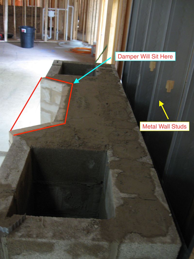
Here's a look at the blocking area behind the firebox once it was completed. On top of the loose fill material next to the firebrick, about a 1" top layer of mortar was placed to seal it off. Note where the damper will be placed, right over the top opening of the fire box.

Next is the start of the construction of the smoke shelf and smoke chamber. The damper in set on top of the firebox as previously seen. Then, 2 courses of ordinary brick are laid up around the opening at the top of the firebox. On top of the second course of brick, a secondary, steel angle lintel is laid. It's the grey angle iron Steve is seen installing above. The magenta colored line, running top to bottom behind Steve, is the plumb bob line that was used as a reference point when laying the stone corners.

Here's another view. The black object in the center is the damper and above it is the grey, secondary lintel. I had it powder coated as well. I'll explain what the fiberglass insulation was used for in a moment.

From the other side here's a good view and description of all the various parts. One thing to note is to leave clearance between the 2nd course of brick and the side of the damper blade. The damper blade needs to move freely and it needs to be removed when properly cleaning the flue.

Here a 3rd course of brick has been laid, starting the forming of the smoke chamber behind the damper. Now the reason for the small, little rolls of fiberglass insulation, placed on the ends of the damper and secondary lintel. They prevent mortar from getting into the ends of the metal damper and secondary lintel. Those metal pieces need room to expand from heat longitudinally so the fiberglass gives it a little cushion room for that expansion. If mortar gets in there, solidifies and tries to prevent the metal from expanding, the metal will expand from heat and crack the mortar joints that will eventually gravitate to the outer stone and crack those mortar joints.

This is an overview of the smoke chamber being completed using taper bricks on the 5th course of brick.

From the side...

...and as seen from the front. The course that is being pointed out; those bricks have been cut on a taper or wedge shape, to start the arch of the top of the smoke chamber. You can now easily see the need for the grey, secondary lintel. It is necessary to support the bricks that are above the front of the damper. The front of the damper slopes and cannot support any bricks above it, hence a secondary lintel is needed.
The first or primary lintel...

...is the one across the top of the face of the firebox opening.

Note that fiberglass was placed on the ends of it as well to provide room for longitudinal expansion of the metal.

That steel lintel supports the lintel stone as seen here before its installation. Using steel angle iron will help the lintel stone carry the weight of all the stone above it. Due to expansion and contraction from the heat of the firebox and the wide opening it spans, the lintel stone, without any additional support, would always be at risk of cracking.
So this concludes Part I of this exciting chapter of, " What in the world does masonry fireplace construction have to do with Garage Journal?!!"
Thanks everyone. More information you can't live without is coming your way!
Thomas
What's under all that pretty granite stone on my fireplace? You've seen smidgens of it being constructed, now let's get an up close and personal look.
What exactly a Rumford designed fireplace is, has been discussed here before, so we'll skip all of that. Go back through this thread or Google it for more background information:
https://www.rumford.com/articleRumford.html
What we're going to look at is how this masonry fireplace was actually constructed and the little nuances in that construction that will provide for an efficient, safe, trouble free and long life, masonry fireplace. Some of this is material is repetitive information but most of the pictures are new.
I'll start with the basic firebox. An overlooked design/construction factor is sizing the firebox mortar joints themselves. On the firebox, those joints are much thinner than normal mortar joints. The firebrick itself is high temperature resistant and high temperature refractory cement was used in the construction. But to aid in making the firebox last longer before the joints breakdown, they are made very thin so the surface of the firebox is almost exclusively firebrick with very little of the joints showing.
The damper I used is an infinitely adjustable damper. That will allow for fine tuning of the damper opening when in use. The hotter the firebox, coals and flue are, the more closed the damper can be resulting in more heat output into the room. It will sit on top of the firebox as seen here. The damper is made of cast iron which can rust over time. It is literally buried within the fireplace during construction and should it ever rust out, it would be an enormous and expensive undertaking to replace it, so I had my entire damper powder coated. That will give it an almost indefinite, useful life.
This is the backing block competed which surrounds the sides and back of the firebox.
Looking at the rear of the firebox you can see a 2" (5 cm) insulating air gap is used. The hottest area of the firebox is at the rear of it. Heat migrates out the backside and if there were combustible material behind it, over time it could ignite. To prevent that, behind my firebox we used only masonry material, the air gap, a shinny metal sheet to reflect heat back into the firebox, metal wall studs, fireproof insulation in the wall cavity and finally fireproof plywood on the outside of the wall which was then faced with exterior brick.
The space between the firebrick and the concrete block was loosely filled with masonry rubble if you will. Pieces of brick, stone and hardened mortar were placed there. The reason this material was left loose was to allow for expansion and contraction of the firebrick. If that space behind the firebrick were filled and hard packed with mortar or cement, the firebrick would eventually crack from being restricted in movement.
Lastly, as seen, the backing block cores themselves were mortar filled. This added to the masonry mass of the fireplace, giving a place for heat to be absorbed and held until the fire is out and then, releasing heat slowly back into the room. This is why the entire fireplace is located within the heated envelope of the home. I don't lose any of the heat out the back or sides of the fireplace to the outdoors. It greatly enhances it's efficiency.
Here's a look at the blocking area behind the firebox once it was completed. On top of the loose fill material next to the firebrick, about a 1" top layer of mortar was placed to seal it off. Note where the damper will be placed, right over the top opening of the fire box.
Next is the start of the construction of the smoke shelf and smoke chamber. The damper in set on top of the firebox as previously seen. Then, 2 courses of ordinary brick are laid up around the opening at the top of the firebox. On top of the second course of brick, a secondary, steel angle lintel is laid. It's the grey angle iron Steve is seen installing above. The magenta colored line, running top to bottom behind Steve, is the plumb bob line that was used as a reference point when laying the stone corners.
Here's another view. The black object in the center is the damper and above it is the grey, secondary lintel. I had it powder coated as well. I'll explain what the fiberglass insulation was used for in a moment.
From the other side here's a good view and description of all the various parts. One thing to note is to leave clearance between the 2nd course of brick and the side of the damper blade. The damper blade needs to move freely and it needs to be removed when properly cleaning the flue.
Here a 3rd course of brick has been laid, starting the forming of the smoke chamber behind the damper. Now the reason for the small, little rolls of fiberglass insulation, placed on the ends of the damper and secondary lintel. They prevent mortar from getting into the ends of the metal damper and secondary lintel. Those metal pieces need room to expand from heat longitudinally so the fiberglass gives it a little cushion room for that expansion. If mortar gets in there, solidifies and tries to prevent the metal from expanding, the metal will expand from heat and crack the mortar joints that will eventually gravitate to the outer stone and crack those mortar joints.
This is an overview of the smoke chamber being completed using taper bricks on the 5th course of brick.
From the side...
...and as seen from the front. The course that is being pointed out; those bricks have been cut on a taper or wedge shape, to start the arch of the top of the smoke chamber. You can now easily see the need for the grey, secondary lintel. It is necessary to support the bricks that are above the front of the damper. The front of the damper slopes and cannot support any bricks above it, hence a secondary lintel is needed.
The first or primary lintel...
...is the one across the top of the face of the firebox opening.
Note that fiberglass was placed on the ends of it as well to provide room for longitudinal expansion of the metal.
That steel lintel supports the lintel stone as seen here before its installation. Using steel angle iron will help the lintel stone carry the weight of all the stone above it. Due to expansion and contraction from the heat of the firebox and the wide opening it spans, the lintel stone, without any additional support, would always be at risk of cracking.
So this concludes Part I of this exciting chapter of, " What in the world does masonry fireplace construction have to do with Garage Journal?!!"
Thanks everyone. More information you can't live without is coming your way!
Thomas
tj675
Well-known member
Thomas,
As usual thank you for the detailed post.
As usual thank you for the detailed post.
Masonry Fireplace Construction Details - Part II
Picking up from the last post regarding fireplace details, for those of you with inquiring minds and who want to know, here is Part II.

This view is from the top of the smoke chamber, looking down. The firebox is below the damper blade which is the black object that has mortar smeared on it. The smoke shelf itself is outlined in magenta. The flue liner will sit directly on top of the arched bricks which make up the smoke chamber as noted. You'll see that in some following pictures.
.jpg")
This is looking down into the smoke chamber with the damper blade, outlined in white, slightly open.

And here is the same view with the damper blade completely open. This is looking straight down into the firebox. Note the opening/closing mechanism on the damper has not been installed yet.

Here, all the lower masonry material that made up the smoke chamber and the damper have now all been faced with stone. The mantle plug has been put in place. Look hard and you can see the brass rotary control knob for the damper right in the middle. Note the fireproof insulation located behind in the wall cavities.

And here is a high overhead view of the previous picture. The arched smoke chamber has been finished with a flat surface where the flue liner will be placed.

The flue liner is getting ready to be placed on top of the smoke chamber. Ray, in orange on the right, is standing just about exactly where the flue liner will be set. Note in the back, drywall has now been installed over the fireproof insulation.

The 1st flue liner has been set in place and leveled on top of the smoke chamber. Concrete backing block will now be built up as the stone work continues up the face and sides of the fireplace.

Something to note; the area between the block and the arched bricks of the smoke chamber have been filled with loose masonry fill material. Keeping it loose will allow for heat expansion of the brick without cracking any masonry joints. This loose fill material in time...

...will be capped with about 1" of mortar wash.

Another view of the smoke chamber, now topped off with the flue liner on it and completely surrounded and leveled to the top of the brick arch. Ready for backing block to be laid up on the sides and stone across the front, on top of the mantle plug.
.jpg")
A debris stick was placed behind the fireplace and moved with each course of backing block as it progressed. That was to prevent misc debris from falling into the air gap and compromising the safety the air gap provides when the fireplace is in operation.

Continuing from this point on is just a matter of building up the backing block and setting stone...


...until you reach the ceiling and you're mostly done with the interior work. Washing the stone, setting the hearth and mantle still remain.
As you can see, taking basic material like...


...sand, concrete block, stone and wood...

...can be turned into something useful and beautiful. It's all in the details!!
Probably more information than you guys wanted. There's a lot to it isn't there? That's 40 years worth of Steve's fireplace building and repairing other mason's mistakes all rolled into a couple of posts. Hopefully, going forward, perhaps a mason might stumble across these posts and gain some insight into a proper way to construct a masonry Rumford fireplace.
On to new business next time. Meanwhile, stay safe everyone and thanks.
Thomas
Picking up from the last post regarding fireplace details, for those of you with inquiring minds and who want to know, here is Part II.
This view is from the top of the smoke chamber, looking down. The firebox is below the damper blade which is the black object that has mortar smeared on it. The smoke shelf itself is outlined in magenta. The flue liner will sit directly on top of the arched bricks which make up the smoke chamber as noted. You'll see that in some following pictures.
This is looking down into the smoke chamber with the damper blade, outlined in white, slightly open.
And here is the same view with the damper blade completely open. This is looking straight down into the firebox. Note the opening/closing mechanism on the damper has not been installed yet.
Here, all the lower masonry material that made up the smoke chamber and the damper have now all been faced with stone. The mantle plug has been put in place. Look hard and you can see the brass rotary control knob for the damper right in the middle. Note the fireproof insulation located behind in the wall cavities.
And here is a high overhead view of the previous picture. The arched smoke chamber has been finished with a flat surface where the flue liner will be placed.
The flue liner is getting ready to be placed on top of the smoke chamber. Ray, in orange on the right, is standing just about exactly where the flue liner will be set. Note in the back, drywall has now been installed over the fireproof insulation.
The 1st flue liner has been set in place and leveled on top of the smoke chamber. Concrete backing block will now be built up as the stone work continues up the face and sides of the fireplace.
Something to note; the area between the block and the arched bricks of the smoke chamber have been filled with loose masonry fill material. Keeping it loose will allow for heat expansion of the brick without cracking any masonry joints. This loose fill material in time...
...will be capped with about 1" of mortar wash.
Another view of the smoke chamber, now topped off with the flue liner on it and completely surrounded and leveled to the top of the brick arch. Ready for backing block to be laid up on the sides and stone across the front, on top of the mantle plug.
A debris stick was placed behind the fireplace and moved with each course of backing block as it progressed. That was to prevent misc debris from falling into the air gap and compromising the safety the air gap provides when the fireplace is in operation.
Continuing from this point on is just a matter of building up the backing block and setting stone...
...until you reach the ceiling and you're mostly done with the interior work. Washing the stone, setting the hearth and mantle still remain.
As you can see, taking basic material like...
...sand, concrete block, stone and wood...
...can be turned into something useful and beautiful. It's all in the details!!
Probably more information than you guys wanted. There's a lot to it isn't there? That's 40 years worth of Steve's fireplace building and repairing other mason's mistakes all rolled into a couple of posts. Hopefully, going forward, perhaps a mason might stumble across these posts and gain some insight into a proper way to construct a masonry Rumford fireplace.
On to new business next time. Meanwhile, stay safe everyone and thanks.
Thomas
Last edited:
Fix Until Broke
Well-known member
Awesome info - Really appreciate the time and effort it takes to share these details!
One question - On either side of the flue, there are big rectangular voids that seem to run all the way from the basement to the top of the chimney cap. Do these serve a purpose? It seems like the whole thing could be a few feet narrower from the basement to the flue and even narrower yet from the flue to the top of the chimney? Or the firebox could be wider?
One question - On either side of the flue, there are big rectangular voids that seem to run all the way from the basement to the top of the chimney cap. Do these serve a purpose? It seems like the whole thing could be a few feet narrower from the basement to the flue and even narrower yet from the flue to the top of the chimney? Or the firebox could be wider?
Grizz1963
Well-known member
.
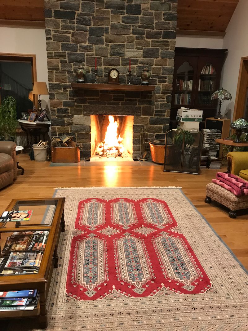
That final pic, with the fire burning - PRICELESS
.
That final pic, with the fire burning - PRICELESS
.
PrairieBoy556
Member
very nice
Fireplace Details 3.1
Those are excellent questions Fix Until Broke! Let's see if I can further illustrate and clarify how and what we were doing with this fireplace.
With this being a clean sheet custom home, to start out I had to decide where I wanted the fireplace in that room. I chased it's placement on the blueprints all over the great room from 3 different walls and a corner. There were pros and cons with several of those different locations. Ultimately I choose the east wall. Then I had to decide how large overall I wanted the fireplace structure. It's a large room with a tall ceiling which I felt needed an equally large fireplace for best overall visual balance and appearance. I decided to make it 8' (2.4 m) wide, so into that space, Steve and I decided a 36" (91 cm) Rumford firebox would work nicely. That size Rumford would give good heat into the large room and overall would have a balanced appearance with the large fireplace structure.
So if the firebox is 36" wide ( and since it's a Rumford, that makes it 36" tall as well) and the overall fireplace structure is 8' wide, there will be void spaces on the sides that are necessary.

I believe these are the voids you were referring to. The basement fireplace block foundation...

... seen here on the left, is separated from the upper fireplace structure by...

...the concrete slab that was poured above the block foundation. That slab was re-bar enforced and is over 10" (25 cm) thick. That keeps those voids you mentioned from going all the way down to the basement.

Over time, eventually those rectangular voids or cavities were solid filled with masonry rubble and mortar. Doing so made them part of the masonry mass and they then provide heat storage when the fireplace is in use. Don't confuse these 2 rectangular void spaces with the area right behind and next to the firebox. That space is loosely filled to allow the firebrick to expand from heat.
As an aside, here are the 2 plumb bob lines that were used as reference for the outside stone corners.

Here is the fireplace going through the roof, that's the flue in the center. On the right, you can see those void spaces or cavities have been solid filled up to the roof line.

The filled void spaces were then capped with 4" block seen above to the left of the flue. All above those capping blocks...

...those void spaces, were left empty all the way up to the crown. No need for masonry mass in the chimney above the roof line.

At the top of the chimney, to construct the crown, those voids needed to be capped. Re-bar was set on the inside corbel space and...

...4" concrete blocks were placed on their sides.

Tar paper was then placed over the blocks and the concrete crown was poured. More information on the chimney crown installation can be found on page 509, post# 10,177.
So, to sum this up, the void spaces are there because of the width of the fireplace. In the heated envelope of the house, those voids were solid filled to add to the masonry mass. Above the roof line, they were left empty or void up to the crown.
Now as for your observation-question, could the whole thing have been made narrower? Certainly! The only reason the fireplace is so wide is for appearance sake. The Rumford firebox dimensions however, are fixed, based on the size opening you have.

To my eye, having a narrow, skinny fireplace...
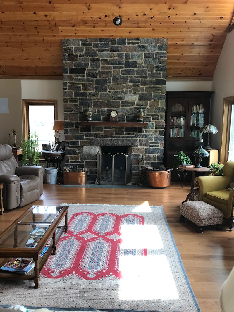
...in that room just would have looked, well.....wrong!

Much the same for the chimney.
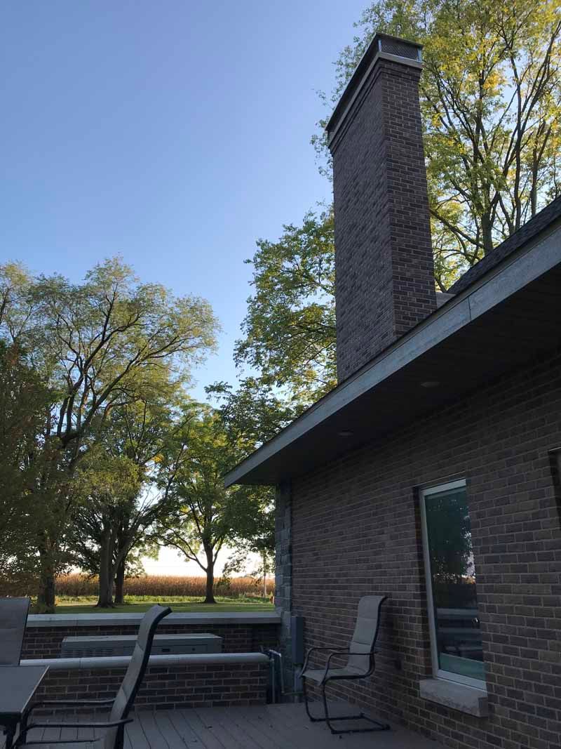
That could have been made narrower...

...but I felt for better appearance, it needed that width. BTW, the chimney is 6' (1.8 m) wide so it's 2' narrower than the fireplace below it.
I hope that answers some of your questions. I appreciate you taking the time to post in and ask them. If it wasn't clear to you, I'm sure others wondered the same things.
Here on Garage Journal, we do these threads for the love of it. I enjoy sharing and exchanging ideas here. There is no financial reward of any sort. I've learned a bunch from you folks and you keep me on my toes! Not a bad thing.
Thomas
Awesome info - Really appreciate the time and effort it takes to share these details!
One question - On either side of the flue, there are big rectangular voids that seem to run all the way from the basement to the top of the chimney cap. Do these serve a purpose? It seems like the whole thing could be a few feet narrower from the basement to the flue and even narrower yet from the flue to the top of the chimney? Or the firebox could be wider?
Those are excellent questions Fix Until Broke! Let's see if I can further illustrate and clarify how and what we were doing with this fireplace.
With this being a clean sheet custom home, to start out I had to decide where I wanted the fireplace in that room. I chased it's placement on the blueprints all over the great room from 3 different walls and a corner. There were pros and cons with several of those different locations. Ultimately I choose the east wall. Then I had to decide how large overall I wanted the fireplace structure. It's a large room with a tall ceiling which I felt needed an equally large fireplace for best overall visual balance and appearance. I decided to make it 8' (2.4 m) wide, so into that space, Steve and I decided a 36" (91 cm) Rumford firebox would work nicely. That size Rumford would give good heat into the large room and overall would have a balanced appearance with the large fireplace structure.
So if the firebox is 36" wide ( and since it's a Rumford, that makes it 36" tall as well) and the overall fireplace structure is 8' wide, there will be void spaces on the sides that are necessary.
I believe these are the voids you were referring to. The basement fireplace block foundation...
... seen here on the left, is separated from the upper fireplace structure by...
...the concrete slab that was poured above the block foundation. That slab was re-bar enforced and is over 10" (25 cm) thick. That keeps those voids you mentioned from going all the way down to the basement.
Over time, eventually those rectangular voids or cavities were solid filled with masonry rubble and mortar. Doing so made them part of the masonry mass and they then provide heat storage when the fireplace is in use. Don't confuse these 2 rectangular void spaces with the area right behind and next to the firebox. That space is loosely filled to allow the firebrick to expand from heat.
As an aside, here are the 2 plumb bob lines that were used as reference for the outside stone corners.
Here is the fireplace going through the roof, that's the flue in the center. On the right, you can see those void spaces or cavities have been solid filled up to the roof line.
The filled void spaces were then capped with 4" block seen above to the left of the flue. All above those capping blocks...
...those void spaces, were left empty all the way up to the crown. No need for masonry mass in the chimney above the roof line.
At the top of the chimney, to construct the crown, those voids needed to be capped. Re-bar was set on the inside corbel space and...
...4" concrete blocks were placed on their sides.
Tar paper was then placed over the blocks and the concrete crown was poured. More information on the chimney crown installation can be found on page 509, post# 10,177.
So, to sum this up, the void spaces are there because of the width of the fireplace. In the heated envelope of the house, those voids were solid filled to add to the masonry mass. Above the roof line, they were left empty or void up to the crown.
Now as for your observation-question, could the whole thing have been made narrower? Certainly! The only reason the fireplace is so wide is for appearance sake. The Rumford firebox dimensions however, are fixed, based on the size opening you have.
To my eye, having a narrow, skinny fireplace...
...in that room just would have looked, well.....wrong!
Much the same for the chimney.
That could have been made narrower...
...but I felt for better appearance, it needed that width. BTW, the chimney is 6' (1.8 m) wide so it's 2' narrower than the fireplace below it.
I hope that answers some of your questions. I appreciate you taking the time to post in and ask them. If it wasn't clear to you, I'm sure others wondered the same things.
Here on Garage Journal, we do these threads for the love of it. I enjoy sharing and exchanging ideas here. There is no financial reward of any sort. I've learned a bunch from you folks and you keep me on my toes! Not a bad thing.
Thomas
Last edited:
Fix Until Broke
Well-known member
Thomas - Thanks for the detailed explanation. Most everything you do has a reason behind it and I was curious about the voids. I agree that it looks "right" in the room and from outside.
I found a nice article about Rumford fireplaces that provides some background on their design and functionality.
https://www.rumford.com/articleRumford.html
No affiliation - just something I found on the internet
I found a nice article about Rumford fireplaces that provides some background on their design and functionality.
https://www.rumford.com/articleRumford.html
No affiliation - just something I found on the internet
Glad the explanation was to your satisfaction. Almost all the other stone and brick masons working on the house had never built a masonry fireplace before and none of them had ever heard of a Rumford fireplace before. They were intrigued with it's construction and surprised at all the small details Steve employed to ensure it's efficiency and longevity. Proof is in it's wonderful radiant warmth throughout that room.
That's a good article on Rumford's. It's the same article I linked to on the previous page, post # 12,376. There's a wealth of good information in it. Thanks for bringing it up again. 40 years ago Rumfords were largely unknown in this country outside of the Northeast. There's much more information available now, thanks to the internet.
As I was preparing the 2 posts about the fireplace construction, I was reminded once more what an enormous undertaking building a house is. There are literally thousands of details that need to be considered.
I'll post shortly about a detail on the house I hadn't given adequate consideration that I successfully corrected last year. It involved a modification...

...that was done in this area. Kudos to anyone if they can figure it out. BTW, that's a look at the underside of one of the roof's lightning rod installations. Secretly I knew you wanted to see one of those.
Thanks to all my friends here. Hope you're all safe and sound.
Thomas
That's a good article on Rumford's. It's the same article I linked to on the previous page, post # 12,376. There's a wealth of good information in it. Thanks for bringing it up again. 40 years ago Rumfords were largely unknown in this country outside of the Northeast. There's much more information available now, thanks to the internet.
As I was preparing the 2 posts about the fireplace construction, I was reminded once more what an enormous undertaking building a house is. There are literally thousands of details that need to be considered.
I'll post shortly about a detail on the house I hadn't given adequate consideration that I successfully corrected last year. It involved a modification...
...that was done in this area. Kudos to anyone if they can figure it out.
BTW, that's a look at the underside of one of the roof's lightning rod installations. Secretly I knew you wanted to see one of those. Thanks to all my friends here. Hope you're all safe and sound.
Thomas
Biff Lungren
Well-known member
- Joined
- Sep 1, 2013
- Messages
- 80
I don't know if it pertains to the lightning rod but I had a galvanic corrosion issue over my office last year, the copper water pipes for the kitchen above were in contact with the steel sink drain. So the wire across the rod catches my eye. Curious to see what I learn next from you.
But what really drove me to respond was this image in my head of you at 45000 feet over the Atlantic for hours building this house for years in your head. Am I close?
But what really drove me to respond was this image in my head of you at 45000 feet over the Atlantic for hours building this house for years in your head. Am I close?
Jeff Ivers
Well-known member
Did you change the routing on the downlead from that lightning rod to provide some insulating space between it and the wood?
MG David
Well-known member
Did you realise that the steel girder under the ridge needed to be earthed even though it has a layer of roof tiles between it and the outside?
offroadtoad
New member
I am going to go with Jeff and guess it has something to do with the rod being anchored to the roof trusses.
One more question regarding the fireplace, near the top of the voids, the is a row of bricks on end. Is this to let the voids breath a little? I would imagine that they heat and cool quite a bit, just curious
Thanks for the excellent tutorial on the Rumford fireplace...fascinating stuff.
One more question regarding the fireplace, near the top of the voids, the is a row of bricks on end. Is this to let the voids breath a little? I would imagine that they heat and cool quite a bit, just curious
Thanks for the excellent tutorial on the Rumford fireplace...fascinating stuff.
Venting The Garage
Yes Bill, you are close, though you're off a bit on the altitude. For most of the flights we'd start out around FL310 to FL350 until we'd burned some fuel and the aircraft was a little lighter. Rarely would we ever be above FL390. FL400 and above would mostly be corporate jets, Gulfstreams and Falcons etc.
Yup, I did a bunch of design work in my head in between position reports out over the Atlantic and some over the Pacific if I was flying to HNL. I am able to mentally go through a specific project and visualize it's general construction. That was very helpful getting small details worked out.
I'm sorry I might have mislead you guys. The lightning rod installation was just fine. No changes have been needed there at all. Since I was working up in that area of the garage attic space, I got a few nice pictures of the installation from underneath that I thought some might find interesting.
For David's observation regarding earthing or grounding as it's refereed to over on this side of the pond, that braided copper wire grounds everything associated with the lightning rods. The copper wire leads to...

...a ground rod sunk several feet into the ground outside of the house. There are a total of 3 ground rods at various locations around the house. More on the house lightning rod installation can be found on page 511, post #10,219.
offroadtoad, thank you for the nice words. Steve reviewed the fireplace posts and felt they were a good explanation of how and what we did on the fireplace.
As for the brick question, I'll assume the picture and void you're referring to was of the very top of the chimney, just under the crown. Those bricks were just used as space fillers and had nothing to do with the voids needing to breathe. I'm glad you asked though, thanks.
Now what I really wanted to talk about was an overlooked problem of heat build up in the garage and separately heat build up in the area where the house electronics are housed.
I'll start with the garage and do a separate post on the electronic heat issue. The only time heat build up is a problem in the garage is in the summer, usually just June through August. The garage floor is Geo Thermal heated in winter just like the rest of the floors throughout the house so the garage was as well insulated as the rest of the house. There are no windows and no air conditioning outlets out there. Because it's so well insulated, with the garage doors shut, I found that parking a car out there would result in trapped heat that would build up day after day. Over time, temperatures would exceed 90ºF (32C). As much as possible, I try to keep the overhead doors shut to keep bugs and critters out and since I dehumidify that space, I want to keep humidity out as well. I needed to find a way to vent the space while bringing in as little humidity as possible.
The garage attic space was cellulose fiber insulated above the drywall ceiling, so above the insulation, the garage attic gets mighty hot even though there is a roof ridge vent and soffit vents. All that attic heat adds to the heat build up of cars parked below. I decided to power ventilate the garage attic space as a first step. As an aside, the garage attic space is sealed and separated from the rest of the house attic areas.

A small, powered, temperature controlled, vent fan was installed near the peak of the garage gable end as seen above.

In the garage attic, this is where a hole was cut for the vent fan. It's situated high enough to assist the roof ridge vent in extracting hot air. It's a slow turning fan, moving about 300 cfpm of air. That slow speed also helps to keep it quiet when operating. That is the north end of the house and I do have ample overhangs there, but I was still concerned about rain being driven into the fan unit resulting in leaks there.
.jpg?width=1920&height=1080&fit=bounds)
To prevent water from getting in, I had this stainless steel shroud fabricated to house the fan unit. It is installed through the hole cut in the side of the house. The air inlet for the fan is from the attic and it's exhausted out the bottom of the unit so water, realistically, can't be blown into the fan. The exhaust outlet has a stainless steel screen over it to keep critters out, mainly birds. I fabricated the stainless flashing to seal the whole assembly to the house. The flashing was installed opposite of what is seen in the photo and the sides of the flashing were placed under the shingles on the exterior wall.

Here's another view if that helps you visualize the shroud and flashing. Disregard how it's all oriented.

In the summer, I replace the garage ceiling attic access panel with a louvered panel so hot air in the garage space can be drawn up, into the attic and exhausted outside by the vent fan. The vent fan is controlled by a thermostat situated in the attic.

When all completed, it's fairly unobtrusive and since it's on the back of the house, my neighbors are the only ones who get to admire the craftsmanship of it all. I'm happy to report that it works well. Virtually silent in operation, summer garage temperatures now rarely get above the low 80's by day and by morning, the temp is all pretty well down to ambient. The overall system is very simple and basic. Works good and should last a long time!
I really didn't give heat build up out there much thought. I knew I didn't want to provide air conditioning. It was all a matter of doing a better job of removing hot air during the afternoon and evenings than a passive ridge vent could do. I've been asked if I'd do anything different with the house. This is one I'd have done while the house was under construction. It would have been so much simpler then! Thanks all.
Thomas
.......
But what really drove me to respond was this image in my head of you at 45000 feet over the Atlantic for hours building this house for years in your head. Am I close?
Yes Bill, you are close, though you're off a bit on the altitude. For most of the flights we'd start out around FL310 to FL350 until we'd burned some fuel and the aircraft was a little lighter. Rarely would we ever be above FL390. FL400 and above would mostly be corporate jets, Gulfstreams and Falcons etc.
Yup, I did a bunch of design work in my head in between position reports out over the Atlantic and some over the Pacific if I was flying to HNL. I am able to mentally go through a specific project and visualize it's general construction. That was very helpful getting small details worked out.
Did you change the routing on the downlead from that lightning rod to provide some insulating space between it and the wood?
I'm sorry I might have mislead you guys. The lightning rod installation was just fine. No changes have been needed there at all. Since I was working up in that area of the garage attic space, I got a few nice pictures of the installation from underneath that I thought some might find interesting.
For David's observation regarding earthing or grounding as it's refereed to over on this side of the pond, that braided copper wire grounds everything associated with the lightning rods. The copper wire leads to...
...a ground rod sunk several feet into the ground outside of the house. There are a total of 3 ground rods at various locations around the house. More on the house lightning rod installation can be found on page 511, post #10,219.
......
One more question regarding the fireplace, near the top of the voids, the is a row of bricks on end. Is this to let the voids breath a little? I would imagine that they heat and cool quite a bit, just curious
Thanks for the excellent tutorial on the Rumford fireplace...fascinating stuff.
offroadtoad, thank you for the nice words. Steve reviewed the fireplace posts and felt they were a good explanation of how and what we did on the fireplace.
As for the brick question, I'll assume the picture and void you're referring to was of the very top of the chimney, just under the crown. Those bricks were just used as space fillers and had nothing to do with the voids needing to breathe. I'm glad you asked though, thanks.
Now what I really wanted to talk about was an overlooked problem of heat build up in the garage and separately heat build up in the area where the house electronics are housed.
I'll start with the garage and do a separate post on the electronic heat issue. The only time heat build up is a problem in the garage is in the summer, usually just June through August. The garage floor is Geo Thermal heated in winter just like the rest of the floors throughout the house so the garage was as well insulated as the rest of the house. There are no windows and no air conditioning outlets out there. Because it's so well insulated, with the garage doors shut, I found that parking a car out there would result in trapped heat that would build up day after day. Over time, temperatures would exceed 90ºF (32C). As much as possible, I try to keep the overhead doors shut to keep bugs and critters out and since I dehumidify that space, I want to keep humidity out as well. I needed to find a way to vent the space while bringing in as little humidity as possible.
The garage attic space was cellulose fiber insulated above the drywall ceiling, so above the insulation, the garage attic gets mighty hot even though there is a roof ridge vent and soffit vents. All that attic heat adds to the heat build up of cars parked below. I decided to power ventilate the garage attic space as a first step. As an aside, the garage attic space is sealed and separated from the rest of the house attic areas.
A small, powered, temperature controlled, vent fan was installed near the peak of the garage gable end as seen above.
In the garage attic, this is where a hole was cut for the vent fan. It's situated high enough to assist the roof ridge vent in extracting hot air. It's a slow turning fan, moving about 300 cfpm of air. That slow speed also helps to keep it quiet when operating. That is the north end of the house and I do have ample overhangs there, but I was still concerned about rain being driven into the fan unit resulting in leaks there.
To prevent water from getting in, I had this stainless steel shroud fabricated to house the fan unit. It is installed through the hole cut in the side of the house. The air inlet for the fan is from the attic and it's exhausted out the bottom of the unit so water, realistically, can't be blown into the fan. The exhaust outlet has a stainless steel screen over it to keep critters out, mainly birds. I fabricated the stainless flashing to seal the whole assembly to the house. The flashing was installed opposite of what is seen in the photo and the sides of the flashing were placed under the shingles on the exterior wall.
Here's another view if that helps you visualize the shroud and flashing. Disregard how it's all oriented.
In the summer, I replace the garage ceiling attic access panel with a louvered panel so hot air in the garage space can be drawn up, into the attic and exhausted outside by the vent fan. The vent fan is controlled by a thermostat situated in the attic.
When all completed, it's fairly unobtrusive and since it's on the back of the house, my neighbors are the only ones who get to admire the craftsmanship of it all.
I'm happy to report that it works well. Virtually silent in operation, summer garage temperatures now rarely get above the low 80's by day and by morning, the temp is all pretty well down to ambient. The overall system is very simple and basic. Works good and should last a long time!I really didn't give heat build up out there much thought. I knew I didn't want to provide air conditioning. It was all a matter of doing a better job of removing hot air during the afternoon and evenings than a passive ridge vent could do. I've been asked if I'd do anything different with the house. This is one I'd have done while the house was under construction. It would have been so much simpler then! Thanks all.
Thomas
Last edited:
Thirdyfivepickup
Well-known member
I still say this is the greatest post on the face of the internet, bar none.
rlwhitetr3b
Well-known member

Sweet Old Bill
Well-known member
You might want to review prior to the dreaded test; a Terraplane might be what you were referring to.
rlwhitetr3b
Well-known member
Oh ****, you are right. I'm dead!!
Cooling Home Electronics
Many thanks Thirdyfivepickup for that vote of support! If nothing else, it might have the most pages attached to it!
See, Sweet Old Bill has visited the shop in person, he's plied the lovey Miss Chris with chocolates and I've conversed with him a time or two over the years. I know he's more than ready for the test as he has clearly shown. rlwhitetr3b you live just a few miles away, you might want to stop by in the near future and do some extra special cramming for the test. It couldn't hurt!
Now let's press on with another item I underestimated when I built the new house that might be of interest.

Underneath the stairs is where I placed all the home electronics equipment. That small, triangular shaped room is behind the wood cabinet above and behind the solid door on the right.
.jpg?width=1920&height=1080&fit=bounds)
Here's a different look at it around the corner. The area highlighted behind the grandfather clock is the interior space used as a mechanical chase for the house. That chase is where the A/C duct work and some home electrical wiring is placed. It extends from the basement to the second floor. To the left of the clock, behind the door is the room under the staircase, with the stairs above it. I decided that would be a very central location for electronics, plus it would utilize a small, unusually shaped room. Note the passive vent above the door.

Here's a look in that room under the stairs. You can see the angled stairs above the black, electronics rack. That rack is bolted to the wall that has the chase on the other side of it. The rack needed to be short so when opened...

...it would clear the landing of the stairs above it. Using a hinged rack allows for easier access behind the various components. The rack doesn't hold everything, but it does hold the vast majority of house electrical equipment.
Three things became a problem as time went on. One is, I wound up installing more equipment in the rack than I had originally envisioned. Two, the components operate at a much higher temperature than I had thought and lastly, many components turned out to be larger in size. I did this part of the initial design around 2014-15 and electronics, outside of the run-of-the-mill audio visual components were not considered. Cable boxes, routers, switches, WiFi components, SONOS components and other miscellaneous equipment over time had to be installed. As a consequence, the equipment is bunched close together and it all generates heat. Some components run over 95ºF (35C) when they aren't being used, and operate at even higher temps when they are in operation.
Heat is the enemy of electrical equipment. Excessive heat leads to a shorten life span and less than optimum performance. I had hoped that the passive vent placed over the doorway, seen in the second picture at top, would provide adequate venting of hot air out of the room. It turned out that vent wasn't enough, I had to mechanically move hot air out of that room.


I installed this wall fan unit above the rack that in turn exhausts air out of the small electronics room and into the chase. Since the attic air spaces in the house are conditioned, I had no worries about evacuating hot air into a really cold space. I just wanted the hot air removed from that room.
Additionally, I installed...


...this enclosed fan unit on top of the rack. In that location, it pulls air up, through and out the top of the rack. Then the wall fan unit removes hot air out of the room. New, cooler air is drawn into the room under the door. The operation of these fan units are tied together with a common temperature controller and are whisper quiet.
The upshot of it all is, the room stays near house temperature (it's about 6º warmer) when no high heat equipment like the receiver is operating. If the receiver is operating, the temperature on top of the rack rarely exceeds 88ºF (31C). I don't have a A/C outlet in there, so just circulating ambient air through the rack and evacuating it out of the room keeps the equipment temperatures cool enough that they won't be damaged from heat.
In retrospect I would have provided for more air circulation in that room. As it turns out, the actions I've take seem to be adequate enough. I hope this information is helpful for anyone out there that might be doing some electronic installation in a small, enclosed space. Live and learn.
Thanks all.
Thomas
Many thanks Thirdyfivepickup for that vote of support! If nothing else, it might have the most pages attached to it!
See, Sweet Old Bill has visited the shop in person, he's plied the lovey Miss Chris with chocolates and I've conversed with him a time or two over the years. I know he's more than ready for the test as he has clearly shown. rlwhitetr3b you live just a few miles away, you might want to stop by in the near future and do some extra special cramming for the test. It couldn't hurt!
Now let's press on with another item I underestimated when I built the new house that might be of interest.
Underneath the stairs is where I placed all the home electronics equipment. That small, triangular shaped room is behind the wood cabinet above and behind the solid door on the right.
Here's a different look at it around the corner. The area highlighted behind the grandfather clock is the interior space used as a mechanical chase for the house. That chase is where the A/C duct work and some home electrical wiring is placed. It extends from the basement to the second floor. To the left of the clock, behind the door is the room under the staircase, with the stairs above it. I decided that would be a very central location for electronics, plus it would utilize a small, unusually shaped room. Note the passive vent above the door.
Here's a look in that room under the stairs. You can see the angled stairs above the black, electronics rack. That rack is bolted to the wall that has the chase on the other side of it. The rack needed to be short so when opened...
...it would clear the landing of the stairs above it. Using a hinged rack allows for easier access behind the various components. The rack doesn't hold everything, but it does hold the vast majority of house electrical equipment.
Three things became a problem as time went on. One is, I wound up installing more equipment in the rack than I had originally envisioned. Two, the components operate at a much higher temperature than I had thought and lastly, many components turned out to be larger in size. I did this part of the initial design around 2014-15 and electronics, outside of the run-of-the-mill audio visual components were not considered. Cable boxes, routers, switches, WiFi components, SONOS components and other miscellaneous equipment over time had to be installed. As a consequence, the equipment is bunched close together and it all generates heat. Some components run over 95ºF (35C) when they aren't being used, and operate at even higher temps when they are in operation.
Heat is the enemy of electrical equipment. Excessive heat leads to a shorten life span and less than optimum performance. I had hoped that the passive vent placed over the doorway, seen in the second picture at top, would provide adequate venting of hot air out of the room. It turned out that vent wasn't enough, I had to mechanically move hot air out of that room.
I installed this wall fan unit above the rack that in turn exhausts air out of the small electronics room and into the chase. Since the attic air spaces in the house are conditioned, I had no worries about evacuating hot air into a really cold space. I just wanted the hot air removed from that room.
Additionally, I installed...
...this enclosed fan unit on top of the rack. In that location, it pulls air up, through and out the top of the rack. Then the wall fan unit removes hot air out of the room. New, cooler air is drawn into the room under the door. The operation of these fan units are tied together with a common temperature controller and are whisper quiet.
The upshot of it all is, the room stays near house temperature (it's about 6º warmer) when no high heat equipment like the receiver is operating. If the receiver is operating, the temperature on top of the rack rarely exceeds 88ºF (31C). I don't have a A/C outlet in there, so just circulating ambient air through the rack and evacuating it out of the room keeps the equipment temperatures cool enough that they won't be damaged from heat.
In retrospect I would have provided for more air circulation in that room. As it turns out, the actions I've take seem to be adequate enough. I hope this information is helpful for anyone out there that might be doing some electronic installation in a small, enclosed space. Live and learn.
Thanks all.
Thomas
MG David
Well-known member
Thomas, that is quite a stack. It makes our broad band router look a little inadequate. I bet as a result you can pick up your WiFi in all of the other buildings. Ideal for ordering parts.
I assume you have the video technology to be able to see how the cooking of dinner is coming on in the kitchen when you are the shop working on a car! In my house I have to leave the garage and look through the kitchen window at the oven timer. It doesn't work if she who must be obeyed has shut the curtains! Roll on lighter evenings.
I assume you have the video technology to be able to see how the cooking of dinner is coming on in the kitchen when you are the shop working on a car! In my house I have to leave the garage and look through the kitchen window at the oven timer. It doesn't work if she who must be obeyed has shut the curtains! Roll on lighter evenings.
C.h.r.i.s
Yes David, I've got great WiFi capability in the old shop. Take a look back at page 614, post #12269. I detailed how I boosted the shop WiFi so it's as fast as that in the house. Works good and lasts a long time!
To see how cooking of dinner is coming while I'm out in the shop, I employ an older technology named...

...C.H.R.I.S. It's marvelous technology that at times, doubles as an automatic trash can returner. It's old school technology, but has proven highly reliable with years of perfect operation. It too works good and lasts a long time.
Skating on thin ice Thomas
If you're not having fun, what's the point?!
......... I bet as a result you can pick up your WiFi in all of the other buildings.........
I assume you have the video technology to be able to see how the cooking of dinner is coming on in the kitchen when you are the shop ............
Yes David, I've got great WiFi capability in the old shop. Take a look back at page 614, post #12269. I detailed how I boosted the shop WiFi so it's as fast as that in the house. Works good and lasts a long time!
To see how cooking of dinner is coming while I'm out in the shop, I employ an older technology named...
...C.H.R.I.S. It's marvelous technology that at times, doubles as an automatic trash can returner. It's old school technology, but has proven highly reliable with years of perfect operation. It too works good and lasts a long time.
Skating on thin ice Thomas
If you're not having fun, what's the point?!
Re: C.h.r.i.s
I didn't think an airline pilot would engage in risky behavior. Thomas you have proven me wrong. My better half knows where I sleep. So,,, if I had a similar comment to her such as yours to Chris
I would think I was engaging in risky behavior. Just sayin'.
I didn't think an airline pilot would engage in risky behavior. Thomas you have proven me wrong. My better half knows where I sleep. So,,, if I had a similar comment to her such as yours to Chris
I would think I was engaging in risky behavior. Just sayin'.
Sweet Old Bill
Well-known member
Thomas,
"Skating on thin ice"; I fear that "Was skating on thin ice, prior to his untimely demise!" may be very close. I would recommend: chocolates, flowers, dinner & whatever else Miss Chris may specify.
Good luck, my friend
"Skating on thin ice"; I fear that "Was skating on thin ice, prior to his untimely demise!" may be very close. I would recommend: chocolates, flowers, dinner & whatever else Miss Chris may specify.
Good luck, my friend
More Thoughts on C.H.R.I.S 1.0
Thank you gentlemen for the good wishes.
TR6SR650, it helps that I'm now a retired airline pilot so I feel I can indulge in risky behavior from time to time. A sort of "No guts, no glory" kind of thrill.
Bill, you are a wise man indeed and I fully intend to implement all your suggestions and more should the need arise! Good luck? yeah I just might need that.
It might be helpful, getting back to David, if I were to expand a little on my particular C.H.R.I.S. I've got the original 1.0 version with the rare, always smiling and in a good mood chip. They didn't make many of those so I feel extremely fortunate to have found one. Through the years, everywhere you turn, in newspaper and magazine ads, billboards, TV and now on the internet, folks have done their best to convince me to upgrade to a 2.0 or even a 3.0 version. I once flew with a fellow who had a 5.0. It cost him an arm and a leg to get that version let me tell you. Personally, I don't think it was worth it, but he always seemed to want the latest, greatest and newest. Every time I turned around he was upgrading, or what he thought was an upgrade. To each his own I guess.
It's my feeling that my C.H.R.I.S 1.0 was the best version ever made and that's what I set out to get many, many years ago. So far I've been proven right. Absolutely wonderful tried and true technology. Sometimes old school technology is the best. It certainly is in my case. Good luck with yours.
How am I doing Thomas
How are you doing? I think you are doing excellent. I also have a 1.0 version that was manufactured in a different region of the country. I have to use common sense with mine because my 1.0 can become feisty. My 1.0 version has lasted 50 years and I feel my training was complete during the first 40 years. My initial mistake was attempting to train my version to my likes and dislikes. After I realized that I was the one to be trained everything went well.