To avoid these ads, REGISTER NOW!

Show us your welding projects

RossRinSD

Member
Joined
Feb 22, 2010
Messages
7
Location
Fallbrook, CA
hey guys, first post :)

as to the circle tricks, im currently a 1st year apprentice metal fab for a rally car shop, so im working my way through the learning process also.

The boss told me the most important aspect is a dry run. Make a pretend/practice sweep and make sure you can do the whole sweep in one arc. If not, break it up into even sections and practice the **** out of your starts and stops to minimise visual and structural impact.

As to my projects, im currently of work for 2 months due to being a retard and breaking my finger lol, so i have nothing awesome to show ... but will be sure to get some as soon as im back :)

I found a quick sidestep and squeeze the trigger again before the bead cools and stops glowing worked best for me.

But, I've never had any sort of instruction with this stuff. My boss got tired of the 2 or 3 day turnaround on stuff we farmed out, so she let me pick up a Hobart 135. We started with the flux core till the spool ran out, and then picked up the MIG conversion and learned that one, too.
 
To avoid these ads, REGISTER NOW!

bluebolt

Well-known member
Joined
Dec 28, 2008
Messages
5,434
Location
Benton LA
Buddy wasn't happy with his adapter that he has to run on his 427 ford. It's a dove intake, and he has to adapt it to a dominator flange, it makes thing really tall. I guess dove at one time made a few intakes with dominator flanges but they are not currently available. Or so I've been told....
168366_10150100449047888_527327887_6198855_1797463_n.jpg


So I called in a favor from a friend, and had him mill off .750 inch off the intake, and also .750 inch off the adatper

190169_10150111457172888_527327887_6318364_5414639_n.jpg


189929_10150111457232888_527327887_6318365_1499571_n.jpg


We took it to my shop and welded the adapter to the manifold
188866_10150113921717888_527327887_6341536_6166365_n.jpg


And after some grinding inside, smoothing out the transitions and opening up the inside to the larger flange it came out pretty good
184768_10150114728017888_527327887_6347576_1491280_n.jpg

Nice! So is the motor going in the Mustang or 1967 Fairlane?
 

mrpowderkeg

Well-known member
Joined
Dec 9, 2008
Messages
776
Location
Bismarck North Dakota
That intake is for the mustang, Dove medium riser heads. BUT things may have changed, there is talk of going tunnel port heads and going for broke on it. The heads for the mustang are done, but we are not happy with the results. The machinist didn't do what we wanted and we were left with good but no optimal flow numbers. I think the heads will be on ebay this winter... Maybe the intake will be to...

The engine in the Fairlane is a real 406.
 

KMinAF

Well-known member
Joined
Mar 5, 2011
Messages
698
Location
Fairview Utah
This is my recumbent that I made from plans sourced at recycledrecumbents.com

It has been a blast to ride as well as the most comfortable bike that I have ever ridden.

I used my Lincoln Weld Pack 155 with fluxcore wire turned way down low. It was made from two old mountain bikes, some electrical conduit and lots of spare bike parts. After completion I had the frame powder coated and it has held up great.
 

Attachments

  • IMG_0752.jpg
    IMG_0752.jpg
    152.2 KB · Views: 431
Last edited:

ZTFab

Well-known member
Joined
Jan 6, 2008
Messages
397
Location
Upland, CA
Some Sheet metal parts for I prototype I started building today.

These are made from 16ga (.062") cold rolled steel. After I sheared and broke them I TIG welded them with .030" ER70S-2 wire using a "lay-wire" technique.

Parts tacked up

Photos_0-2.jpg


Corner to corner fitment

Photos_1-4.jpg


Welded

Photos_2-3.jpg


Photos_4-3.jpg


Hammer shown for scale reference

Photos_5-3.jpg


All done!

Photos_8.jpg
 

welder4956

Well-known member
Joined
Apr 8, 2010
Messages
3,052
Location
Birmingham, AL USA
We took it to my shop and welded the adapter to the manifold
188866_10150113921717888_527327887_6341536_6166365_n.jpg


And after some grinding inside, smoothing out the transitions and opening up the inside to the larger flange it came out pretty good
184768_10150114728017888_527327887_6347576_1491280_n.jpg

Beautiful work! Just wondering, do you have any problem with distortion when welding machined parts like this? I have always worried about aluminum parts, especially engine parts, distorting when doing repairs and try to bolt or clamp them to something heavy to keep them from pulling.
 

flingwing1969

Well-known member
Joined
Oct 30, 2011
Messages
138
Location
Shasta County - In the Shadow of Lassen Peak
Some Sheet metal parts for I prototype I started building today.

These are made from 16ga (.062") cold rolled steel. After I sheared and broke them I TIG welded them with .030" ER70S-2 wire using a "lay-wire" technique.

Parts tacked up

Photos_0-2.jpg


Corner to corner fitment

Photos_1-4.jpg


Welded

Photos_2-3.jpg


Photos_4-3.jpg


Hammer shown for scale reference

Photos_5-3.jpg


All done!

Photos_8.jpg

TIG is so sweet! Lovely work.:bowdown:
 

b-body-bob

Well-known member
Joined
Oct 10, 2011
Messages
1,621
Location
Almost Heaven
Beautiful work! Just wondering, do you have any problem with distortion when welding machined parts like this? I have always worried about aluminum parts, especially engine parts, distorting when doing repairs and try to bolt or clamp them to something heavy to keep them from pulling.

I think your concern is valid. I had an aluminum bellhousing crack radially and after it was tigged the dowel holes didn't line up to the dowels in the back of the block.
 

z28snksknr

Well-known member
Joined
Jul 8, 2009
Messages
1,827
Location
Turnersville, NJ
I'll post my boogers:

A shot of one of the welds on my Y-pipe for my camaro exhaust before I cleaned it up:
29000bf8.jpg


Welding a round piece of pipe is a challenge. Notice how inconsistent my bead is. That's because it's my first time with round stock (and I'm a newb).

The whole piece (not all are my welds):
cb1e55c3.jpg


I never got so much satisfaction from looking at a hunk of twisted metal tubing.

It's a shame I'm too poor to buy much steel for projects these days.
 
Last edited:

mrpowderkeg

Well-known member
Joined
Dec 9, 2008
Messages
776
Location
Bismarck North Dakota
Beautiful work! Just wondering, do you have any problem with distortion when welding machined parts like this? I have always worried about aluminum parts, especially engine parts, distorting when doing repairs and try to bolt or clamp them to something heavy to keep them from pulling.

For me it's hit or miss. I've done some GM intake manifolds where for some reason they start leaking water from a corroded cruddy intake. That's a mess to do, but so far they never leak or are warped to where they cause a problem. We figured that if this 427 intake warped we would have it machined on the mill, but when we checked it, the intake flanges and carb flange are good to go with no machining necessary.
 

outtaplace

Active member
Joined
Jan 21, 2011
Messages
37
Location
Central NJ
Some Sheet metal parts for I prototype I started building today.

These are made from 16ga (.062") cold rolled steel. After I sheared and broke them I TIG welded them with .030" ER70S-2 wire using a "lay-wire" technique.

ZTFab - Super sweet welds!! Can you describe or show an example of a "lay-wire" technique in action/progress??
 

ZTFab

Well-known member
Joined
Jan 6, 2008
Messages
397
Location
Upland, CA
ZTFab - Super sweet welds!! Can you describe or show an example of a "lay-wire" technique in action/progress??

Thanks.

Here is a quick model I made in Solidworks to show how I did that particular joint style.


You literally Lay the wire in the groove of the joint and apply a slight amount of pressure, bending the wire so that a portion of it is laid flat. I used a steady hand motion with the torch to achieve a smooth bead profile. Amperage, speed, and knowing how to watch the puddle are key in not letting the wire ball up on the end.


Hope that helps.

WeldingDemo_LayWireTechnique.jpg
 

outtaplace

Active member
Joined
Jan 21, 2011
Messages
37
Location
Central NJ
Thanks.

Here is a quick model I made in Solidworks to show how I did that particular joint style.


You literally Lay the wire in the groove of the joint and apply a slight amount of pressure, bending the wire so that a portion of it is laid flat. I used a steady hand motion with the torch to achieve a smooth bead profile. Amperage, speed, and knowing how to watch the puddle are key in not letting the wire ball up on the end.


Hope that helps.

WeldingDemo_LayWireTechnique.jpg

So it looks like you're melting the wire into both sides of the base metal simultaneously...pretty cool stuff. I need to practice, lol. Thanks for the cool drawing.
 
To avoid these ads, REGISTER NOW!

SWT Racing

Well-known member
Joined
Jun 13, 2009
Messages
137
Location
South Carolina
Thanks.

Here is a quick model I made in Solidworks to show how I did that particular joint style.


You literally Lay the wire in the groove of the joint and apply a slight amount of pressure, bending the wire so that a portion of it is laid flat. I used a steady hand motion with the torch to achieve a smooth bead profile. Amperage, speed, and knowing how to watch the puddle are key in not letting the wire ball up on the end.


Hope that helps.

WeldingDemo_LayWireTechnique.jpg

Nice!

I've never tried the laywire technique on steel before. I did try it out a long time ago on some thick aluminum on DC using Helium once, which was pretty interesting.
 

SWT Racing

Well-known member
Joined
Jun 13, 2009
Messages
137
Location
South Carolina
Beautiful work! Just wondering, do you have any problem with distortion when welding machined parts like this? I have always worried about aluminum parts, especially engine parts, distorting when doing repairs and try to bolt or clamp them to something heavy to keep them from pulling.

Castings like an intake manifold are usually pretty rigid, with a lot of shape that helps prevent much distortion. I always check, but the softer gasket will usually take up the variance. If the 1050 Dominator flange did not have the somewhat vertical section, and was instead a flat plate and welded onto the manifold, I would expect more distortion.

If it is a smaller part, or uses a machined surface with an o-ring, things get a bit more complicated.:)
 

ZTFab

Well-known member
Joined
Jan 6, 2008
Messages
397
Location
Upland, CA
Small material rack for my brother's truck.

1.25" x .090" square tubing to 11ga cold rolled steel.

TIG with .045" Er70s-2 on my Syncrowave 250DX TIGRunner, straight Argon @ 20cfh, 3/32" thoriated Tungsten, #5 cup with 125amp base machine setting using the foot pedal "till it felt good". :)

Photos_11.jpg


Photos_10-1.jpg


Photos_7-2.jpg


Photos_4-4.jpg


Photos_3-3.jpg
 

welder4956

Well-known member
Joined
Apr 8, 2010
Messages
3,052
Location
Birmingham, AL USA
Small material rack for my brother's truck.

1.25" x .090" square tubing to 11ga cold rolled steel.

TIG with .045" Er70s-2 on my Syncrowave 250DX TIGRunner, straight Argon @ 20cfh, 3/32" thoriated Tungsten, #5 cup with 125amp base machine setting using the foot pedal "till it felt good". :)

With 0.045" wire, do you use a handheld wire feeder, such as a TIG PEN or cold wire feeder? I used to weld hermetically sealed valve bonnets on nuclear subs using 0.035" or 0.045" wire that was cut from a spool and straightened. I like welding with small diameter wires, but the smallest diameter I can get locally in straight lengths is 1/16". I can see where a TIG wire feeder would be handy on the work bench using a 10 lb. or 30 lb. spool of 0.045" wire.
 

ZTFab

Well-known member
Joined
Jan 6, 2008
Messages
397
Location
Upland, CA
With 0.045" wire, do you use a handheld wire feeder, such as a TIG PEN or cold wire feeder? I used to weld hermetically sealed valve bonnets on nuclear subs using 0.035" or 0.045" wire that was cut from a spool and straightened. I like welding with small diameter wires, but the smallest diameter I can get locally in straight lengths is 1/16". I can see where a TIG wire feeder would be handy on the work bench using a 10 lb. or 30 lb. spool of 0.045" wire.

Nope, fed by hand while wearing a pair of Tillman kidskin TIG gloves.

I have down to .030" 70S TIG wire in standard 36" lengths. In fact, I stock .030", .035", .045", 1/16", and 3/32" in 70S. I also carry down to .045" in my aluminum and stainless wires.

I buy it from weldingsupply.com since they stock it and are usually cheaper than my LWS.

I prefer thinner diameter fillers as I have better control of how much, or little, filler I apply to the joint.
 

MP&C

Well-known member
Joined
Oct 21, 2009
Messages
4,396
Location
Leonardtown, MD
Working on a 55 Chevy wagon, didn't really want to use those contact pads between the A pillar and the door, and have seen too many failures in the spring type loom deals. While working on replacing the hinge pins, began to brainstorm while the hinge was apart.

HPIM6385.jpg


The cut into the hinge was 5/8 deep, Hinge cleaned up, scribed, and then cut using .045 cutoff wheel in 4-1/2 grinder:

HPIM6563.jpg


HPIM6565.jpg


HPIM6566.jpg


HPIM6572.jpg


I used some 16 ga steel bent into small angles. Angle pieces trimmed to fit opening, tacked in place, and heat applied to follow bends of the hinge:

HPIM6573.jpg


HPIM6576.jpg


HPIM6577.jpg


Mig was used to tack weld and join the two halves, the tig was used to final weld the angles to the hinge. (not very nice looking, but functional :D) Then some grinding to smooth things out:

HPIM6580.jpg


HPIM6581.jpg


Wire dumps out right by the pivot point for minimal movement during opening/closing.


HPIM6582.jpg


Wires and protective sleeving run in place........the first wire used as a pull wire, tied a knot into it and taped some sleeving tight on the other side of the knot to pull it through:


HPIM6419.jpg


HPIM6420.jpg


HPIM6421.jpg


HPIM6422.jpg


Then the same pull wire was stripped in the middle to pull back and forth, using as a pull wire.

HPIM6424.jpg


HPIM6429.jpg


HPIM6439.jpg


Installed, a view under the dash to show the hinge both open and closed with no chaffing issues:

HPIM6437.jpg


HPIM6438.jpg


Should be able to adapt this for other vehicle hinges.


*****************************
edited for a detail I missed ..........
*****************************


One thing to keep in mind is the effect the spring mechanism has on your wiring path. Shown here in the original form, this hinge uses two spring clips riveted onto the hinge bracket to hold the door open. (red arrows)


hinge1.jpg


Over the years, some of the more "well used" hinges may show some metal has worn away where these clips have rubbed across the hinge. Where I wouldn't worry so much about this effect if rubbing across a solid piece of steel, after modification we now have a piece of 16 ga metal that would be more susceptible to damage and possible intrusion of the wire path given the same amount of wear. With that in mind, drill/grind out the rivet and remove the clip adjacent to the wire path to eliminate this as a future hazard... Shown below you can see the lower spring clip has been removed. Three remaining per door should still be more than sufficient to hold the door open. For this modification adapted to other door hinges with exposed springs to hold the door open, be aware of the hazard they pose in pinched/damaged wiring and plan accordingly.


hinge2.jpg
 
Last edited:

e-tek

Well-known member
Joined
Dec 19, 2007
Messages
10,690
Location
Saskatoon, SK
Robert - that is just a fantastic bit of design and fabricating! Great idea and it turned out wonderfully. I've seen a LOT of ways to get wiring to the door, but this is one of the best (OK the best!) I've seen.

Thanks - as usual - for sharing your work and ideas.:bowdown:
 

lilredex

Well-known member
Joined
Apr 29, 2006
Messages
5,943
Location
Toronto
Here are a few....

A bender.


Uploaded with ImageShack.us

Drill press fence for the times you want all those holes in a straight line.


Uploaded with ImageShack.us

Another version with a moveable pointer to space the distance between the holes (as you go without measuring).


Uploaded with ImageShack.us

Drill press hold downs.


Uploaded with ImageShack.us

Vee blocks for drilling round stock on the drill presss.


Uploaded with ImageShack.us

These are for changing U-joints in a vise when you are all alone........sure beats trying to postion loose sockets or whatever.


Uploaded with ImageShack.us

This is your helper to hold up the other end of that drive shaft. Has also been used to weld up small projects............easy to move outside and do the crappy jobs there. Made from an old brake disc and other junk on hand.


Uploaded with ImageShack.us

Woodworking vise. The screw and nut were a garage sale find, with 1/2" plate pieces, rods, etc, from the junk box. The wooden jaws are hard Maple boards scrounged from crates.


Uploaded with ImageShack.us

Sliding carriage for a drill press vise......no excuse for holding things in your hand with this device.


Uploaded with ImageShack.us

As you can see, an entirely new door opens in your workshop......once you have the capability to weld. Got lots more of this kind of stuff if there is interest.
 

1984Datsun

Well-known member
Joined
Jul 25, 2011
Messages
139
Location
Michigan
Weld, weld, weld... what have we got here? :bounce:

I finally got around to starting my welding cart project... I need to get the Hobart off of the old coffee cart so I can put tools and **** on it and roll it all around the shop...

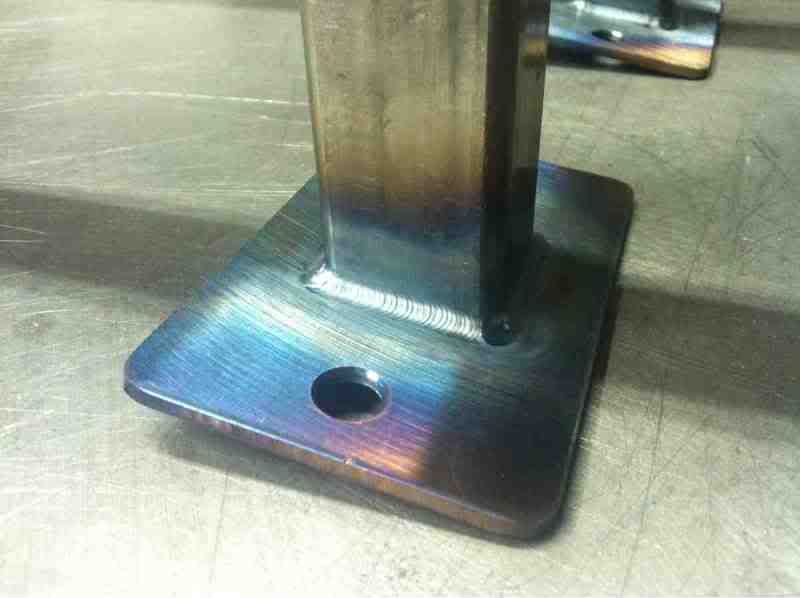
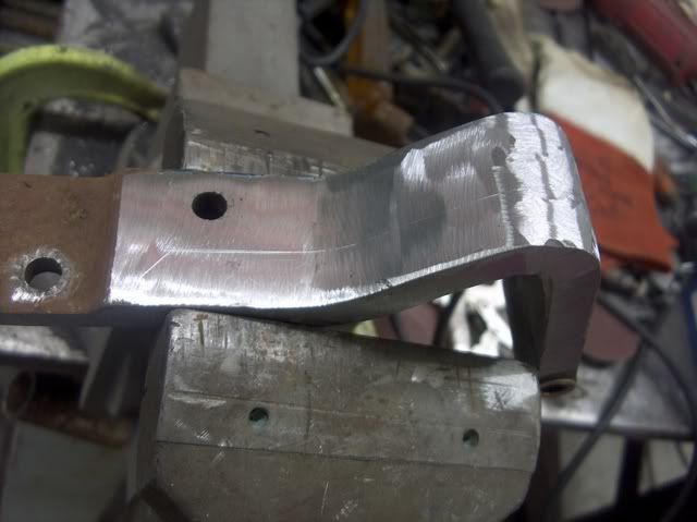
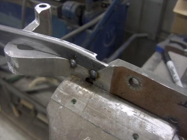
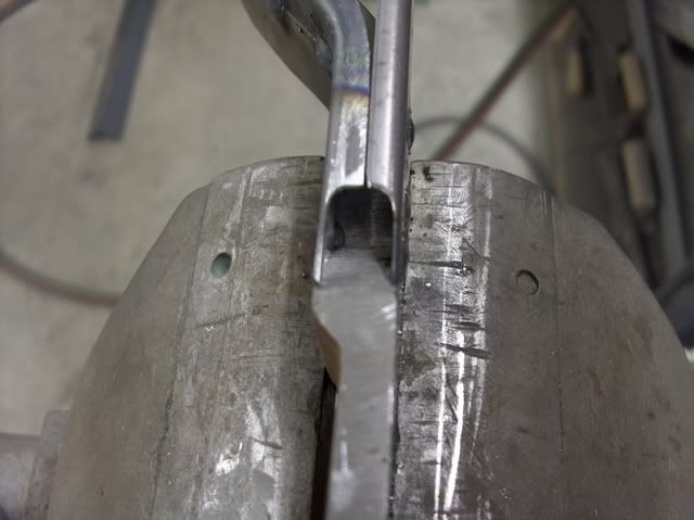
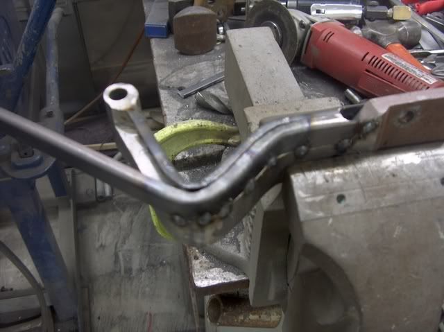
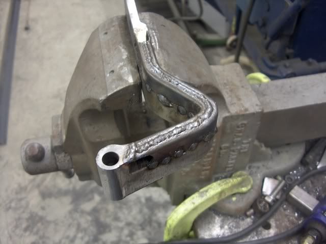
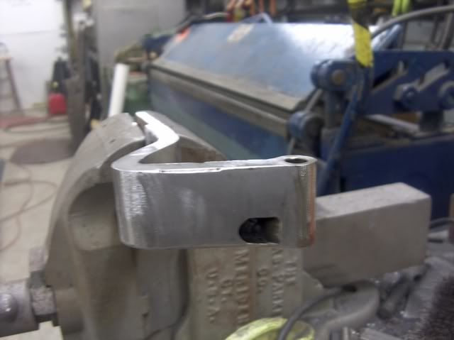
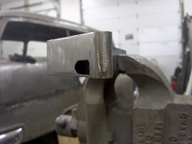
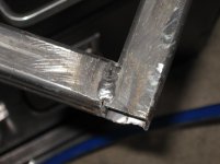
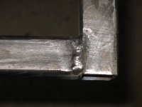
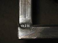
So... here are close ups of a few welds...

attachment.php


attachment.php


attachment.php


Not the best I've ever done, but definitely much better than the worst I've ever done. Good enough for me, and they'll definitely hold, especially once I actually get the cart closer to done, where I plan to weld the hell out of it at every joint until it really is one solid piece... (all I mean is going in and filling all empty joints... anything that can be welded will be welded)

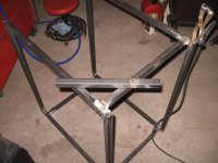
and an overall picture of the current cart progress... that stray piece of square tube with the welds on it is made of the cut off pieces that I'm too lazy to throw into the scrap bin... I'm making the last bottom support out of them...

Hiding in the bottom left corner, you can see part of the formerly pristine file cabinet that I'm going to use as the toolbox on my cart... it's already broken in... scratches and burnt paint... since I used it as a welding table... :spit:

attachment.php


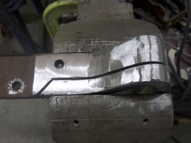
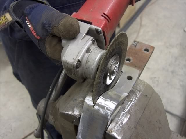
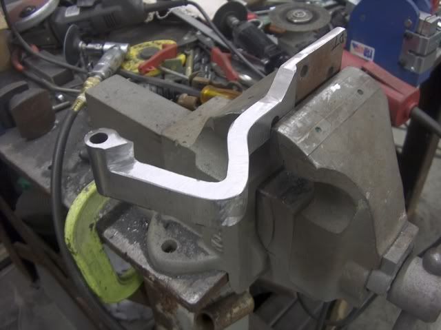
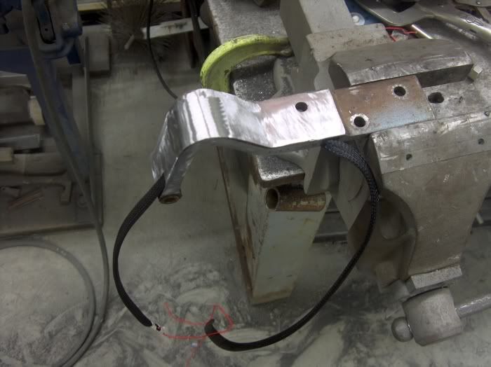
Been grinding, welding, fabbing, and swearing all day yesterday and today... Still got a little more to do yet, most important would be mounting the casters... I will fab up gusset plates that will be welded on each bottom corner for more strength and support, and will drill and tap them for the 3/8"x16NC threads on the casters...

The casters I'm going to use are all swivel casters... the two with brakes will be on the front of the cart (which is where you look right at the control panel of the welding power source) so if I back it into a corner, I can still get to the locking casters to keep it from rolling over my *** in the middle of running a weld bead... if you put them on the back, I reckon you'd be pissed at yourself for doing so... :lol_hitti

And yes, that's a can of gas way over yonder there... don't yell at me...

I'm using my Hobart Handler 140... running .035" flux core wire. I personally like flux core more than solid gas shielded wire on this kind of project... stronger and the nature of flux core and its slag just makes me take my time... however, the MIG process would be much more convenient on thin **** where the stop/start method is very handy... Slag and stop/start do not mix, according to my common sense. Not to mention how the slag from flux core likes to roll around to the backside of thin stuff... hmm...

My next project will be even more interesting... 1/8" or 3/16" plate front bumper for the Ranger... it'll be complete with provisions for a 12,000 pound winch and a set of KC Hilites Daylighters... and will be welded from the front and the back to ensure strength...

Gotta scoop up the material, and then I can do some CAD (cardboard aided design) and get the bumper looking right, then bring it all to the local CC where they have a CNC plasma cutting machine... much more accurate and mcuh less time consuming than cutting each piece with a cut off wheel.

I'll probably switch to the 10 pound spool of .030" flux core for that one, since I'm dead sure that a partial 2 pound spool of .035" ain't gonna be enough... since this thing will be running full out, I'll be taking the side off and putting a box fan in to cool it off good so the duty cycle should hopefully be extended. If that 'experiment' does work, then I might be rigging up a mini squirrel cage blower and a custom side cover... function over form... if something makes something better, I'll probably do it... :beer:
 

Attachments

  • weld1.jpg
    weld1.jpg
    135.1 KB · Views: 8,738
  • weld2.jpg
    weld2.jpg
    144.1 KB · Views: 8,731
  • weld3.jpg
    weld3.jpg
    144 KB · Views: 8,711
  • welding cart progress.jpg
    welding cart progress.jpg
    136.4 KB · Views: 8,709

IDASHO

Well-known member
Joined
Mar 5, 2007
Messages
1,809
Location
Moscow, Idaho
Lots of cool projects in here!

Traditionally all of my fabrication projects revolve around solving some sort of problem. I also like to incorporate "found objects" in my projects, in an attempt to recycle old steel as well as add some flavor to it.

This is one of the latest. A very simple boot scraper, made out of some sort of gear I found in the metal dumpster at work. The broom head was also in the garbage at work, somehow broken in half.

So the broom head pieces were cut to similar lengths, the gear cut in half, and a bit of scrap angle iron was used as cross members.

Then a bit of paint... and Boom! A cool boot scraper for the front door. :beer:

boot01.jpg


boot02.jpg
 
Last edited:

mcmlvif100

Well-known member
Joined
May 2, 2010
Messages
627
Location
Northern Indiana
It is most likely the drive sprocket from a Caterpillar (or similar brand) track-type tractor / crawler. Lots of miles on that one. Clever re-purpose. Like the colour but it would look good in Rustoleum "old Cat yellow" as well.
 

G1K

Well-known member
Joined
Feb 10, 2005
Messages
1,073
Location
Buffalo, NY
I'll play too:

A tool I made from a craftsman socket, some round steel bar, and a gage pin. It's used to engage a propriatary nut.

tool.jpg


Stand for a surface grinder
grinderstand.jpg


Closeup of bracket
standstop.jpg


Good end of an aluminum brembo lever welded to a replacement business end:
lever.jpg


Triumph TR-6 Replacement crossmember
oldandnew.jpg

weldingpin.jpg

weldingpinsupport.jpg
 
To avoid these ads, REGISTER NOW!
Top Bottom